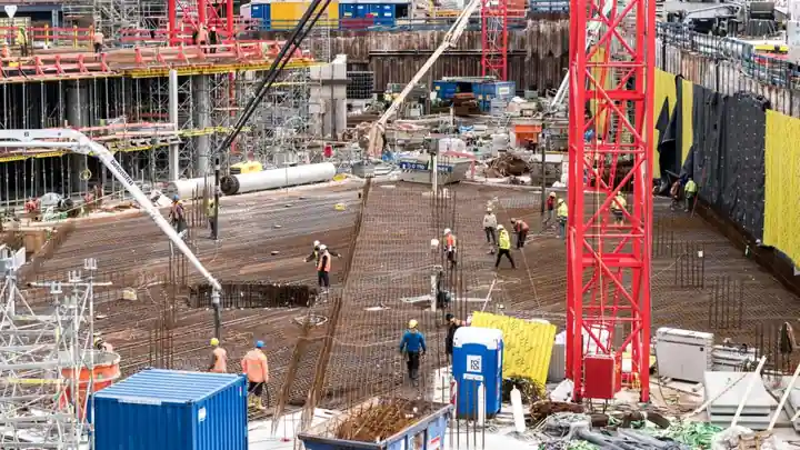
For underground civils work, a gantry crane is typically the only lifting device that can run the full bore length, straddle the invert, and re-position segment-by-segment without blocking rail or muck trains; a gantry crane is essentially a bridge crane on two portal legs running on ground rails, with separate drives on each leg to prevent skew above roughly 30 m span [S5].
Three families dominate tunnel bids in 2026: rubber-tired gantries (RTG) for precast segment yards and short TBM back-up moves, rail-mounted truss-leg gantries for rail-track and segment erection inside the bore, and modular lattice tower systems (climb-on-jack) for shaft and station work where headroom exceeds 80 m. Choosing between them is mostly a function of segment mass, available invert width, and whether the crane must keep pace with a moving TBM or stay stationary at a shaft head.
Load class and span: where each gantry class fits
The CIMOLAI MST 65-19 rubber-tired gantry is rated at 65 t (71.7 US ton) and is explicitly marketed for tunneling and special applications, with a fleet that also includes the 50 t MST 47 and the 100 t MST 100-7 [S2][S3]. For heavier precast liners or full-ring handling, the same CIMOLAI range scales to the MST 400 rubber-tired straddle carrier, which sits in the same engineered-product family rather than the mobile-gantry catalogue [S3]. On the heavier end, the Weihua 550 t gantry has completed factory load testing for high-tonnage rail and tunnel-track installation, using two cranes in tandem to carry the rail tracks into the tunnel [S6].
Truss-girder portal gantries specified for tunnel-track work typically run 35-120 t with 23-35 m spans, with below-ground hook travel of 13.5-40 m to clear tunnel cross-section; the MGh35 and MGh120 reference models pair 20 m/min crane travel (VFD on the MGh120, 0-15 m/min) with 0-8 m/min trolley creep for segment alignment, and total installed power of 110-112 kW [S8]. For shaft and station work where vertical reach dominates, modular lattice systems such as the Sarens SLTS 3500 (1,300 t per tower, up to 170 m height) replace the bridge-and-trolley layout with a stackable tower that climbs on its own jacking system and couples with strand jacks for multi-tower lifts [S1].
Mobility: rubber-tired versus rail-launched inside the bore
Rubber-tired gantries (CIMOLAI MST 47 / MST 65-19 / MST 100-7, Eden Tech eMOBILIFT 40 at 40 t) carry their own diesel or hydrostatic drive, need no embedded track, and re-position between casting cells in 1-2 minutes; CIMOLAI also offers fully battery-electric and hybrid variants (eMOBILIFT 40, 50 t MBH at 15 m working height) for indoor or emission-restricted shafts [S3]. Inside an active TBM back-up, however, an RTG rarely fits: the invert carries conveyor, muck cars, and ring-build rails, so a rail-launched truss-leg gantry on temporary rails is the practical answer for continuous segment erection behind a shield.
Rail-launched gantries share their drive architecture with overhead tower crane base bogies, but the headroom constraint is inverted: in a 6-8 m metro bore, the crane structure must clear ventilation and the segment feeder at roughly 4.5-5.0 m while still leaving trolley stroke for lifting segments 2-3 m above invert. The MGh35 / MGh120 pair, with 10 m and 16.5 m net lift above ground, is sized for that envelope; the 13.5-40 m below-grade hook travel on the same line covers shaft lowering rather than bore work [S8].
Drive train, power, and control: what to verify on the data sheet
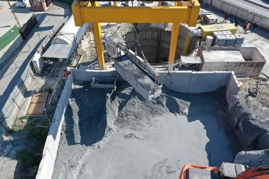
Truss-girder gantries for tunnel-track work in the 35-120 t class are delivered with 110-112 kW total installed power, single-speed 20 m/min crane travel on lighter units, and VFD 0-15 m/min plus 0-8 m/min trolley creep on heavier units for segment alignment within ±10 mm [S8]. Trolley lift speeds of 2.5-10 m/min are typical, with the lower end reserved for heavy lifts where inertial swing of a fresh segment ring would overpower the slings [S8].
For the lattice-tower / strand-jack class, the lifting energy is hydraulic, not electric: the Sarens SLTS 3500 is a freestanding modular tower that can be coupled in pairs (vessel lift) or in multi-tower arrays (module lift), with platform and ladders built into the standard tower sections for crew access during the climb sequence [S1]. Hoist drift after stopping is a known failure mode on wire-rope hoists used on these gantries; the root causes are brake wear, incorrect air-gap, VFD brake-delay mismatch, and contactor / rectifier faults, all of which must be cleared before the gantry returns to segment service [S7].
Selection criteria and comparison against the three main types
Four criteria separate the candidates on a tunnel bid: lifting capacity, mobility (rubber-tired vs rail-launched vs self-climbing), power and headroom envelope, and footprint. A simple lined-up read: CIMOLAI MST 65-19 RTG, 65 t, rubber-tired, diesel-electric, low headroom, fits segment yards and short TBM back-up moves; the MGh120 truss-leg gantry, 120 t over 35 m span, rail-launched, 110 kW, 16.5 m hook lift, is the workhorse for rail-track and segment erection in mid-size metro bores [S2][S8]. The Sarens SLTS 3500 lattice tower system, 1,300 t per tower up to 170 m, self-climbing, freestanding, takes over where the headroom is too tall for a bridge girder and the load is too concentrated for a mobile crane on the surface [S1].
If the project needs rail-track installation rather than segment handling, the comparison shifts: Weihua's 550 t tandem-gantry lift, which uses two cranes on shared rails to carry the track panels into the bore, shows the practical ceiling for in-tunnel rail-track work without resorting to a crawler crane on the portal bench [S6]. For shipyard-style heavy assembly (hull section turnover, double-trolley segmented turn-over), the four-track double-trolley shipbuilding gantry with 100-1,500 t lift and 2-15 m/min hoist is the design lineage, but that footprint is not transferable to a tunnel invert [S4][S5].
Limitations, failure modes, and what the data sheet does not show

Standard gantry frames are designed for above-ground open yards; a tunnel application loads the structure differently because the cross-wind that drives a wind gauge and rail clamp on a yard crane is absent, while longitudinal temperature deformation across a 30+ m span is amplified inside a constant-temperature bore. For spans above 30 m, the conventional fix is one rigid leg plus one flexible leg connected by a ball hinge, which keeps the portal statically determinate and avoids lateral thrust into the rails [S5]. The data sheet rarely lists this hinge detail; it has to be specified at RFQ.
Two failure modes repeat on real sites. First, skew travel: with both legs driven from a single cab and a single drive line, even a small rail misalignment builds lateral resistance fast, so each leg of a long-span gantry is driven separately, with a wind gauge and rail clamp interlocked to the travel mechanism to prevent storm slippage in surface staging yards [S5]. Second, hoist drift on stop: if the brake releases before the VFD has finished ramping torque to zero, the load creeps, which on a segment lift can crush the segment-feeder track; the cure is a matched VFD brake-delay card and a verification procedure on the first lift of every shift, not a larger motor [S7].
Standards, sourcing, and what to pin down before signing
Design verification should be against the relevant national crane standard (FEM 1.001, ASME B30 series, GB/T 3811 depending on jurisdiction) and the project-specific tunnel safety case; the OEM data sheet will state capacity, span, speed, and power but rarely the wind, seismic, or fatigue classification. The Sarens SLTS 3500 documentation, for example, lists 1,300 t per tower, 170 m height, modular containerised shipping, and a custom-made scope that can be paired with strand jacks, lifting beams, skidding systems, or Sarbogies, all of which become project-specific deliverables rather than catalogue line items [S1].
For an underground project, three trackable signals separate a workable bid from a risky one: (1) the OEM can show a tunnel-specific reference list, not just yard and shipyard work; (2) the drive train is VFD-controlled on hoist and at least one travel axis (matches the 0-15 m/min and 0-8 m/min creep on the MGh120 baseline) [S8]; (3) the brake and hoist-control package has a documented drift-test procedure, which is the single most common in-tunnel incident on wire-rope gantries [S7]. Buyers comparing shortlists should also rule out catalog units that are not IP55-or-better on outdoor motors, since the IP55 versus IP65 dust-and-water choice is the cheapest way to cut motor failures on a long-duration tunnel site [S7]. For an alternative read on adjacent heavy-lift decisions in the same procurement window, see this AC motor spec guide for heavy industrial use and this diesel generator set ratings and cooling tradeoffs piece, both of which feed the same gantry power and standby architecture.