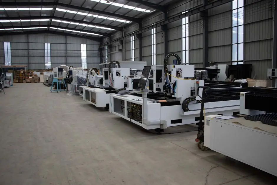
Per the International Federation of Robotics figures cited by Assembly Magazine and reproduced in [S1], 50 percent of all the world's industrial robots are used for welding (33 percent for spot welding, 16 percent for arc welding, and 1 percent for other welding operations), reinforcing the design principle that a welding robot production line is best treated as a synchronized workcell rather than a single robot.
The typical cell combines a 6-axis articulated or gantry manipulator, a welding power source, a wire feeder, a torch, fixtures, and a positioner, all sequenced through offline programming software and seam-tracking sensors [S3][S2]. The full cycle (part load, fixture clamp, weld, eject, transfer) is automated in most modern cells rather than only the arc-on time [S1].
Core Equipment: Robot, Power Source, Positioner, Fixture
The robotic manipulator is the centre of the cell, selected on payload (kg), reach (mm), and compatibility with the welding process (MIG/MAG, TIG, spot, or laser) [S3]. Multi-axis articulated arms are the default for arc welding because their joint rotation lets the torch reach seam orientations a Cartesian gantry cannot [S1]. Sheet metal, predominantly aluminum and mild or stainless steel, is the most common workpiece class for robotic arc welding [S1].
The welding power source and torch must be rated for automated duty cycles, with bulk electrode wire supply and a wire feeder for MIG and most TIG cells, and resistance electrodes for spot cells [S1][S2]. DS Technology pairs a TRUMPF laser source for 3D laser cutting, trimming, and welding in mixed cells [S2]. Positioners are equally critical: a two-axis turntable or a head-tailstock positioner is the standard way to present the workpiece to the torch with repeatable accuracy, and it directly controls weld-seam orientation [S3]. Fixtures are designed for joint tolerance and repeatable positioning because cumulative error is what destroys weld consistency on multi-pass parts [S2].
Software and Sensing Layer: Offline Programming, Seam Tracking, Vision
Offline programming and simulation software lets engineers develop, test, and optimize weld paths and robot trajectories before installation, which compresses commissioning time and avoids production-line downtime [S3]. Robotmaster is one established offline-programming package used alongside in-house robot calibration to generate collision-free paths for complex multi-axis cells [S2].
Inside the running cell, real-time process control software holds energy input, wire feed speed, and travel speed within a defined envelope, and laser-based seam tracking adjusts the robot path online to follow the actual joint, not the nominal CAD joint [S3]. Machine-vision systems complement this by locating the part on the fixture before the arc strikes, which is essential for high-mix cells where fixture repeatability alone is not enough [S3]. The combined software layer is what turns a collection of machines into a responsive line, so a product design change is absorbed as a program change rather than a mechanical rebuild [S3].
Layout and Workcell Configuration
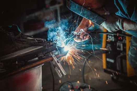
Most automated welding falls into three process families: arc welding (MIG or TIG), spot welding, and laser welding, and the workcell layout is set by which family dominates [S1]. Two-station rotary cells with a turntable are common in automotive bumper welding because they let one station weld while the operator loads the other, cutting arc-on dead time [S1]. For larger or longer parts, a head-tailstock positioner with two axes of rotation gives better torch access than a single-axis table [S3].
Peripheral hardware inside the cell includes nozzle cleaning stations, tool changers for cells that switch between MIG and TIG torches, fume extraction, and safety fencing; missing any one of these typically limits the cell to a lower duty cycle than the robot's nameplate rating [S1][S3]. A modular cell layout also makes future line expansion easier: extra stations can be added to a base conveyor or indexing table without re-engineering the upstream robot [S2]. Lincoln Electric's standard robotic cells are sold as pre-engineered packages sized from small-part arcs up to large fabrication lines [S5]. For process basics and selection context, the welding and cutting tool encyclopedia page lays out the broader equipment family that a robotic cell plugs into.
Process Selection: MIG/MAG, TIG, Spot, Laser
Process choice drives almost every other spec in the cell. MIG/MAG (including pulse and CO2 variants) is the workhorse for high-throughput mild-steel and aluminum fabrication and is the easiest to automate because wire feed and shielding gas are simple to control [S2]. TIG, including smooth-wave TIG, is specified where appearance and low heat input matter, such as premium bicycle frames, EV battery enclosures, and visible stainless seams, because it gives finer control of penetration and fusion at the cost of slower travel speeds [S2].
Spot welding is concentrated in automotive body-in-white, where the original UNIMATE robot was first installed in 1962 [S1]. Laser welding enters the cell when seam width must be very narrow or when the same optical head is also used for 3D cutting and trimming upstream of the weld [S2]. For shops running mixed materials and thicknesses, a smooth-wave TIG or pulse MIG cell reduces distortion compared with conventional CV welding, which is why premium-exterior cells specify it for heat-input and post-weld dimensional control [S2]. The automatic molding line page covers how a comparable integrated production line is laid out in a different process family, useful when comparing automation concepts across disciplines.
Fixtures, Positioners, and Tolerance Management
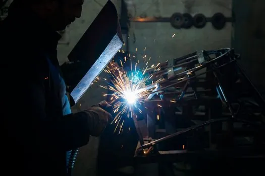
Fixture design is where most cells succeed or fail. Tolerance management on the joint, clamping repeatability, and locating-pin accuracy all directly translate into weld-seam deviation that the robot must absorb; a cell that cannot hold joint gap below a few tenths of a millimetre usually needs seam tracking, not a better robot [S2][S3]. Head-tailstock positioners with servo rotation are the standard for cylindrical or shaft work, while indexing turntables fit flat fabricated panels [S3].
For high-mix low-volume cells, modular fixture plates with a common datum let the same robot weld part A on Monday and part B on Wednesday without re-fixturing the cell, which is the practical meaning of "modular design for future line expansion" in supplier literature [S2]. Compliant force control integrated into the torch mount absorbs small part-to-part variation and is a standard feature on premium cells [S2]. Fixture thermal mass also matters: aluminum fixtures pull heat out of the joint faster than steel, which changes penetration and must be designed in, not discovered at commissioning [S2].
Safety, Fume Control, and Operator Interface
Safety fencing, light curtains, and three-position enabling devices are baseline requirements for any cell where an operator can reach into the robot envelope; the design goal is to keep the operator at a safe distance from arc flash, spatter, and moving axes during automatic cycles [S7]. Fume extraction is sized to the welding process: MIG and flux-cored generate more visible fume than TIG, and laser welding generates fine particulate that needs different filtration [S1][S3].
Operator interface usually runs on the robot teach pendant or a separate HMI, with a small number of pre-defined production recipes selectable by part number; this is what lets a low-skill operator run a high-skill weld cell [S3]. A useful adjacent reference is the conveyor and sorting line encyclopedia entry, which covers the upstream and downstream material-handling layer that any welding cell must hand off to. For background on how an integrated line is sequenced end-to-end, the molding line page provides a cross-industry comparison of workstation linking, conveyor timing, and buffer sizing.
Integration and Supply Chain: Why China-Sourced Cells Are Common
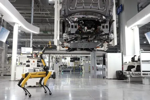
China-based integrators ship a high share of mid-volume arc-welding cells because the regional supply chain bundles the robot, positioner, welding source, safety fencing, and fume extraction from specialised local suppliers, which simplifies mechanical and electrical compatibility [S3]. DS Technology's published work, for example, combines its own robot calibration and offline programming with third-party positioners, TRUMPF laser sources, and downstream automated grinding cells for premium-appearance parts [S2].
IT-ES China (ITES) highlights offline programming, seam tracking, and vision as the three software elements that most often separate a working cell from a stalled one, and recommends verifying them on a supplier-floor demo before purchase [S3]. Standards to anchor the spec on include ISO 10218-1 and ISO/TS 15066 for robot and collaborative robot safety, IEC 60974 for arc welding equipment, and ISO 9283 for robot performance criteria; the welding procedure itself should still be qualified to ISO 15614-1 or the relevant AWS/ASME section. For context on how a different heavy-industry cell is procured, the shot blasting machine sizing and selection guide walks through the same hardware/software/integration decision sequence.
Cost Drivers, ROI, and Common Failure Modes
Robot welding cell ROI is dominated by arc-on hours, not robot price. Between 2018 and 2023 the welding automation market grew at a CAGR of 8.91%, driven mainly by automotive and transportation where duty cycles are high enough to justify a 6-axis cell [S1]. The biggest hidden cost is usually fixturing and integration, not the manipulator, and a rule of thumb in integrator literature is that fixture and engineering can exceed the cost of the robot itself on small-batch cells [S1][S3].
Recurring failure modes in the field are torch crash from poor seam tracking on a part that drifts on the fixture, wire-feed birdnesting from a mismatched liner, and spatter build-up that the cell's cleaning station cannot keep up with at the programmed duty cycle [S1][S3]. When a cell is justified by labour shortage rather than throughput, a low-cost MIG cell on a single-axis positioner is usually the right starting point; when it is justified by appearance and consistency on premium parts, a smooth-wave TIG or laser cell with closed-loop seam tracking and automated grinding downstream is the correct base spec [S2]. For a procurement-side comparison of how supplier ecosystems affect lead time, the shot blasting machine suppliers and manufacturers 2026 spec map is a useful parallel.
Trackable signals before specifying: (1) confirm the joint gap and tolerance budget the fixture can hold, because that decides whether seam tracking is required; (2) request the integrator's offline-programming demo on a representative part to verify cycle time, not just reach; (3) validate fume-extraction airflow against the specific process (MIG, TIG, or laser) before locking the cell footprint.