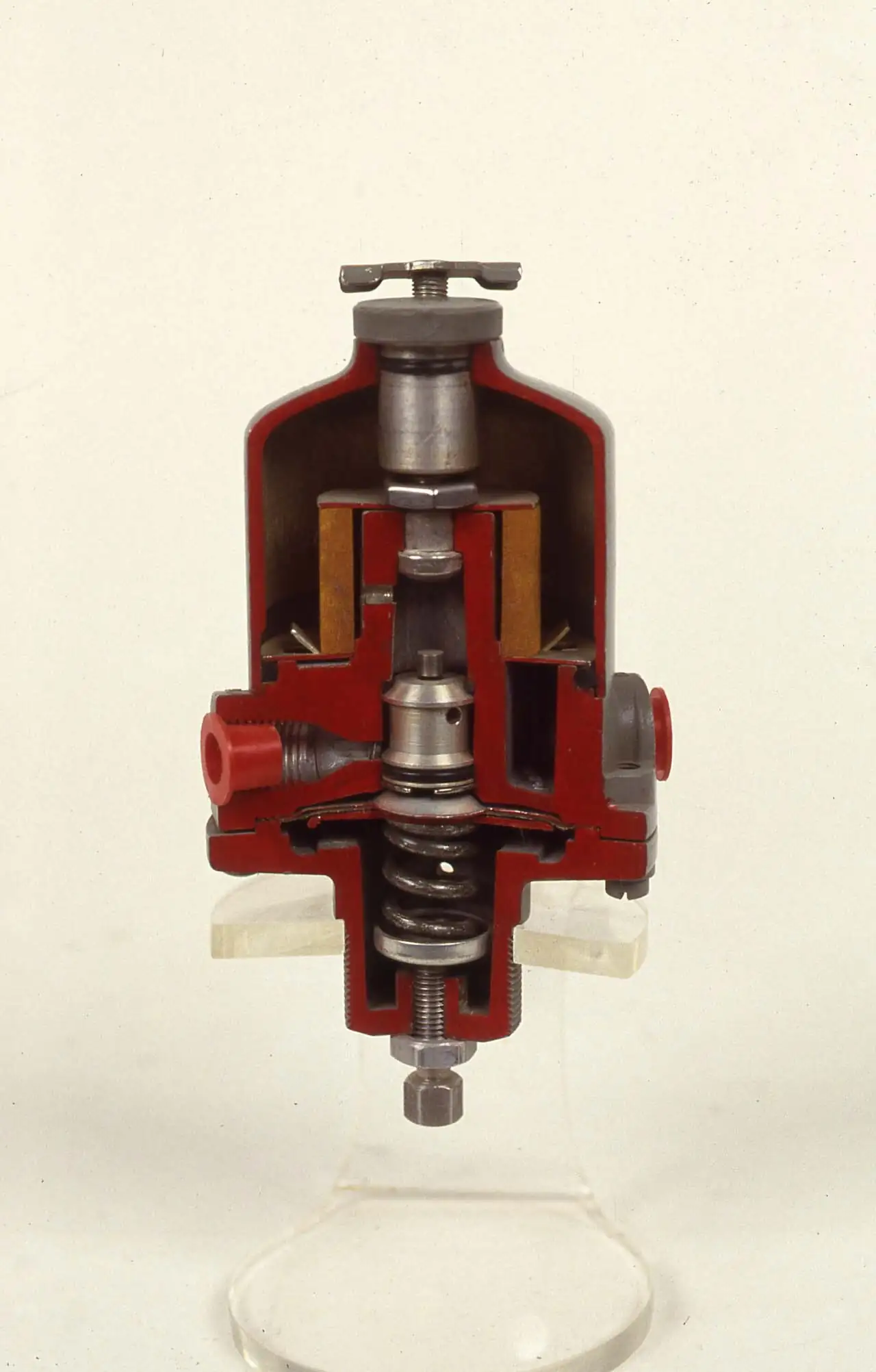
An air dryer removes water vapor from compressed air after the compression stage, so that the delivered air will not condense in downstream piping, instruments, and product. Every cubic meter of intake air carries its humidity into the compressor; squeezing that volume to 7 bar packs roughly eight atmospheres of moisture into one, most of which the aftercooler condenses out as bulk liquid. What remains is vapor, and the dryer exists to strip it to a specified pressure dew point: refrigerated dryers chill the air to 2 to 5 deg C and hold a dew point near plus 3 deg C, desiccant dryers adsorb vapor onto activated alumina and reach minus 40 or minus 70 deg C, membrane dryers permeate it through hollow fibers, and deliquescent dryers dissolve it into a chemical bed. The industry calls the complete machine a compressed air dryer; the duty is one, air whose dew point sits below the coldest point it will ever touch.
Procurement engineers meet these machines on every compressed air system above hobby scale: plant air headers feeding cylinders and tools, instrument air for valve positioners and analyzers, food and pharmaceutical processes, paint shops, ozone generation, and plastics resin conveying. The decision this page settles is narrow and practical: which ISO 8573-1 moisture class the application requires, which technology reaches it at acceptable energy cost, how to size at real working pressure and inlet temperature instead of catalog conditions, and what the RFQ must state so two quotations compare line against line. The answer lands as a line set, class, technology, capacity at stated conditions, purge consumption, and verification instrumentation, and every chapter below feeds it.
This page treats the air dryer as a purchasing object: how refrigeration circuits and desiccant adsorption actually work, what the ISO 8573-1 classes promise in numbers, why purge air dominates lifetime cost, how capacity tables bend under real pressure and inlet temperature, and how all of it combines into a defensible RFQ. It is written for engineers who issue purchase specifications, not for readers who want a brochure summary.
Chapter 1 / 06
What an Air Dryer Is and What Is Being Decided
The controlling concept is pressure dew point, and it deserves a precise sentence. The dew point of compressed air is the temperature at which the air, at its actual line pressure, becomes saturated and water begins to condense; specifying a pressure dew point of minus 40 deg C means the air can cool to minus 40 deg C anywhere in the plant, outdoors, at a valve station, inside an instrument cabinet, before a drop of liquid forms. Note that it is pressure dew point, not atmospheric dew point: the same air released to atmosphere through a tool holds a much lower partial pressure of water and therefore a lower dew point, which is why a dryer that merely looks adequate at the outlet gauge can still freeze an outdoor vent line, or the reverse, why a pressure reducing valve at a point of use quietly buys extra dryness by dropping the partial pressure.
What is actually being decided in this purchase is a purity class, a technology, and an energy budget at the same time, and the three interact. Buying more dryness than needed is silent waste: a heatless desiccant dryer rated minus 70 deg C on a general plant air header consumes 14 to 18 percent of its dried air as regeneration purge, every hour, for decades, to solve a problem that a refrigerated dryer solves for a few kilowatts of refrigeration input. The RFQ decision this page settles is therefore not which brand but which class, which machine reaches that class, and what the machine will cost in energy per year at the plant's real load profile.
Against its neighbors in the air preparation chain, the dryer has a defined seat, and confusing the seats is a common first error. The aftercooler condenses bulk vapor and is not a dryer; a coalescing filter removes oil aerosol but passes vapor; a water separator knocks out free liquid. The dryer sits after the aftercooler and prefilter and removes vapor, and downstream of it the point of use chain takes over: an FRL unit filters, regulates, and lubricates air for cylinders and tools, and it does its job best when the air reaching it is already dry, because a regulator downstream of a wet header rusts and a filter element blinds with rust. A dryer does not remove oil or particles; the purity chain handles those classes separately under ISO 8573-1.
Three standards organize the datasheet. ISO 8573-1 defines purity classes for particles, water, and oil, and its moisture classes, class 1 at minus 70 deg C down to class 6 at plus 10 deg C at 7 bar, are the language every specification should use. ISO 8573-3 fixes how moisture in a compressed air stream is measured, which is what turns a dew point claim into an auditable number. ISO 7183 covers compressed air dryer specification and testing, including the capacity correction conventions discussed in chapter 4. A datasheet quoting none of these three, or quoting a dew point without a pressure, is a price tag, not a specification.
The purchase frame should be the whole system, not the dryer box. The dryer is bought into a chain, compressor and aftercooler, coalescing prefilter with drain, the dryer, an afterfilter for desiccant dust, and condensate handling that separates oil and water legally; each element protects the next, and the drain hardware protects everything from a flooded separator.
Chapter 2 / 06
How Refrigerated and Desiccant Drying Work
A refrigerated dryer is a small refrigeration plant wrapped around an air heat exchanger. Warm compressed air from the compressor aftercooler, typically 35 to 60 deg C, first passes through an air-to-air precooler where outgoing cold air chills it; it then enters the air-to-refrigerant evaporator, where refrigerant boiling at a controlled temperature chills the air to 2 to 5 deg C, condensing most of the remaining vapor; the condensate separates in a demister and drains, and the cold dry air returns through the precooler, recovering energy and warming the outlet above the pipe sweating point. The evaporator and precooler are commonly built as a brazed plate heat exchanger pack on smaller frames, and the refrigerant condenser is an air-cooled finned coil on standard models or a shell and tube heat exchanger where plant cooling water is used. A hot gas bypass valve keeps the evaporator from freezing at low air load, and that valve is the component whose failure most often writes off an evaporator.
The refrigerated machine cannot go below about plus 2 deg C dew point for a physical reason, not a commercial one: colder would freeze the condensate on the exchanger walls and block the air path. Its honest performance is a pressure dew point of plus 3 deg C at 7 bar, ISO 8573-1 class 4, adequate for every indoor plant air duty. Two control philosophies split the family: non-cycling machines run the refrigeration circuit at constant output regardless of load, simple and wasteful at part load, while cycling machines add a thermal mass and track part load like a refrigerator, saving energy on systems that unload nights and weekends. Inlet temperature is the silent killer of both: capacity tables assume 35 to 45 deg C inlet, and hot air from an overloaded aftercooler degrades capacity and trips high temperature alarms.
A desiccant dryer is a chemical machine: two pressure vessels packed with activated alumina, or a blend with molecular sieve for minus 70 deg C duty, alternate between adsorption and regeneration. While one tower dries the full air stream at line pressure, water molecules adhere to the enormous internal surface of the desiccant, an exothermic process that saturates the bed from the bottom up over a fixed cycle. The saturated tower then regenerates: in the heatless design a fraction of the dried air, 14 to 18 percent of capacity, expands down through the bed, and its low partial pressure drags the adsorbed water back out before it is vented. Heated designs add an electric heater in the purge path and cut purge to roughly 7 to 8 percent; blower purge designs push heated ambient air through the bed with a regenerative blower so compressed air purge falls to nearly zero; and heat-of-compression designs steal the heat of an oil free screw compressor to regenerate.
The switching hardware is where desiccant dryers earn or lose their reliability. Towers alternate on a 3 to 10 minute cycle driven by switching valves, often ball or butterfly valves, with each changeover piloted through an air solenoid valve sized for the actuator; the purge exhausts through a dedicated solenoid valve and silencer with a measured orifice; check valves keep line pressure out of the regenerating tower. The control logic lives in a small PLC or a dedicated switching controller, and the single most valuable upgrade is dew point switching: a dew point transmitter at the outlet holds the working tower on line while the measured dew point stays below setpoint, stretching the fixed cycle and cutting purge by vendor-typical 20 to 50 percent on varying loads. Each switching dump is audible as a discrete report through the silencer, and a change in that rhythm is the earliest sign of a leaking valve.
Membrane and deliquescent machines fill the remaining corners. A membrane dryer passes compressed air through bundles of hollow fibers whose walls pass water vapor faster than air; a small purge sweep on the shell side carries the vapor away, the machine is silent, needs no power, and reaches minus 40 deg C class at modest flows, but the fibers are destroyed by oil and liquid water, and dew point rises with flow. The deliquescent dryer passes air through hygroscopic tablets that absorb vapor and dissolve into a drainable brine; it holds roughly plus 10 to plus 15 deg C suppression below inlet temperature, uses no power and no purge and survives unpowered remote sites, which is why it survives at all: for any plant with electricity it is honestly described as a legacy choice.
Chapter 3 / 06
Types, Construction, and Duty Boundaries
Four construction families cover the market, and their boundaries are physical rather than commercial. The refrigerated dryer, cycling or non-cycling, is the default for class 4: one refrigeration circuit, a demister separator, an automatic drain, and a cabinet; hot plant rooms push it to water-cooled condensers and cold outdoor installs need a heated cabinet. The heatless desiccant dryer is the default for class 2, minus 40 deg C: two carbon steel or stainless vessels, four to six switching and check valves, a purge orifice, and a timer, mechanically simple and energetically expensive. Heated and blower purge desiccant units trade capital for purge, with heaters, a blower, and aftercooler stages in the regeneration loop, and the heat-of-compression variant only exists where an oil free screw compressor with the right discharge temperature sits next door.
Construction details that decide service life are unglamorous. Desiccant towers are pressure vessels and should arrive with the certificates the plant's inspection authority expects. Valve quality dominates desiccant reliability because a tower valve that fails to seal sends line pressure into a venting tower; the market splits between multi-port valve blocks, which simplify plumbing but concentrate wear, and discrete ball or butterfly valves, which can be rebuilt individually. Desiccant bed design matters at the edges: bed depth and cycle time set the achievable dew point, a support screen stops attrition dust, and the prefilter described in chapter 5 is what keeps oil from turning a white alumina bed black in a season. Refrigerated frames live or die by their drain: a float or timed drain that sticks open wastes the compressed air it was built to protect, and zero-loss drains are the standard answer.
Duty boundaries can be stated bluntly. No refrigerated dryer reaches below plus 2 deg C pressure dew point; anything colder needs desiccant or membrane. No membrane dryer handles plant-scale flow economically; it is a point-of-use instrument. No heatless dryer should be bought without signing off on its purge bill; at 14 to 18 percent of capacity it is often the largest single air consumer on site. No deliquescent dryer should feed instruments or anything freezing-exposed; its suppression, not absolute, dew point moves with inlet temperature. And no dryer of any family fixes oil or dirt: those are the coalescing and particulate classes of the same ISO 8573-1 table, and a wet-oil complaint is usually a filter problem wearing a dryer costume.
The table below compresses the families into the form a specifier can scan before writing the RFQ.
Family
Construction core
Duty boundary
Refrigerated, non-cycling
Plate or coil exchangers, refrigeration circuit, demister, automatic drain
Plus 3 deg C class 4; constant refrigeration input regardless of load
Refrigerated, cycling
Thermal mass around the evaporator, cycling compressor
Same dew point; part load savings, higher cost, thermal lag
Heatless desiccant
Twin towers, switching valves, purge orifice, timer or dew point control
Minus 40 to minus 70 deg C; purge is 14 to 18 percent of capacity
Heated and blower purge desiccant
Towers plus heater, blower, regeneration aftercooler
Same class at 7 to 8 percent purge or near zero with blower heat
Heat of compression desiccant
Towers integrated with an oil free compressor discharge
Near zero purge; only where the compressor and layout cooperate
Membrane
Hollow fiber bundles, sweep purge
Point of use flows to minus 40 deg C class; oil intolerant
Deliquescent
Dissolving tablet bed, brain drain, no power
Plus 10 to plus 15 deg C suppression; legacy and remote duty only
Chapter 4 / 06
Key Specification Parameters
The purity class is the first datasheet line because every other line bends around it. ISO 8573-1 fixes moisture classes at a reference pressure of 7 bar, and the table below is the vocabulary a specification should use verbatim.
refrigeration kW small; heaters 1 to 30 kW class on heated desiccant
Electrical load and part load behavior of cycling control
Condenser arrangement
air-cooled finned, or water-cooled shell and tube
Plant room heat rejection and hot ambient tolerance
Drain type
float, timed, or zero-loss electronic
Air wasted at the separator and freeze behavior outdoors
Test basis
ISO 7183 capacity and dew point test, ISO 8573-3 measurement
Comparability of two quotations line against line
The capacity row hides the most common sizing error in the discipline. Nominal capacity is stated at reference conditions, typically 7 bar and 35 or 45 deg C inlet, and capacity falls when the plant runs at lower pressure or higher inlet temperature: a dryer that carries 1000 m3/h at 7 bar and 35 deg C may carry only 70 to 80 percent of that at 6 bar and 50 deg C, and the correction factors are published per ISO 7183 convention on every respectable datasheet. Sizing must start from the plant's worst real condition, minimum weekend pressure, maximum summer inlet temperature, and apply the published factors before adding margin. The purge row is the second trap and only applies to desiccant machines: purge percentage is of dryer capacity, not of plant demand, so an oversized heatless dryer purges on its oversize.
The dew point row should be read together with the pressure row, because dew point is a pressure-dependent promise. A machine certified at 7 bar does not deliver the same dew point at 10 bar, so state class, dew point, and pressure in one line, for example ISO 8573-1 class 2, minus 40 deg C at 7 bar. Where the plant regulates down at point of use, physics pays a dividend: a pressure reducing valve dropping 7 bar air to 3 bar lowers the water partial pressure and with it the delivered dew point, roughly 10 deg C at typical ratios, which is why instrument air specified at minus 40 at the dryer arrives at the positioner drier than it left the header.
The technology comparison below places the families against each other on the three axes a buyer actually pays for, achievable dryness, purge energy, and electrical input, and it is the table a specification meeting should argue from.
Technology
Achievable PDP at 7 bar
Purge air share
Energy character
Refrigerated non-cycling
plus 3 deg C, class 4
none
Constant refrigeration input, kW scale
Refrigerated cycling
plus 3 deg C, class 4
none
Refrigeration input tracks air load
Heatless desiccant
minus 40 to minus 70 deg C
14 to 18 percent
Compressed air is the energy, metered at the purge orifice
Externally heated desiccant
minus 40 to minus 70 deg C
7 to 8 percent plus heater
Electric heater kW plus reduced purge
Blower purge desiccant
minus 40 to minus 70 deg C
near zero, blower sweep
Ambient air heated by electric or steam, regenerative blower power
Heat of compression
minus 40 deg C class
near zero
Uses compressor heat; pairs with oil free screw machines
Membrane
minus 40 deg C class at small flow
sweep ratio typically 10 to 20 percent
No power; pressure drop is the cost
Deliquescent
plus 10 to plus 15 deg C suppression
none
Chemical refill is the cost; no power, no purge
Chapter 5 / 06
Selection Decision Factors and RFQ Language
The decision sequence is short enough to run as a checklist in a specification meeting, and each step eliminates a class of quotations before price comparisons begin.
Fix the purity class from the application, not from habit: general indoor plant air is class 4, instrument air and any outdoor run is class 2 to 3, food, pharma, ozone feed, and resin drying follow the process spec.
Map the class onto technology: class 4 means refrigerated; class 2 to 1 means desiccant or membrane at point of use; nothing else reaches.
Size at worst real conditions: minimum working pressure, maximum inlet temperature, applied correction factors, then margin.
Price the energy honestly: purge percentage times capacity times hours times compressor specific power, before comparing purchase prices.
Decide on dew point switching on any desiccant machine whose load varies; it is the cheapest purge cut available.
Specify the filter train: coalescing prefilter with drain before a desiccant bed, afterfilter for dust after it, gauges across both.
Plan the bypass and drains: full-flow bypass for maintenance, oil-water condensate separation, and freeze protection on outdoor drain legs.
Fix the verification: a dew point transmitter at the outlet, its calibration interval, and the ISO 8573-3 measurement basis for audits.
Purge air is not free compressed air; it is air the plant generated, aftercooled, filtered, and dried, then thrown away. A heatless dryer sized 1000 m3/h at 15 percent purge consumes 150 m3/h continuously; on a screw compressor at a typical 0.10 to 0.13 kWh per cubic meter of specific power that is roughly 120,000 to 150,000 kWh per year at 8000 running hours, several times the purchase price of the dryer, every year. Heated, blower purge, and heat-of-compression designs exist to attack exactly this line, and dew point switching attacks it again by stretching cycles when the measured dew point allows. The interaction with compressor control is real: on a plant trimmed by a VFD compressor, purge becomes a larger share of demand as process air falls at night, so a VFD plant benefits most from dew point switching, and the dryer and compressor strategies should be written by the same engineer.
Selection among technologies is a matter of boundaries rather than brand. A refrigerated dryer wins every class 4 duty outright on energy: a few kilowatts of refrigeration against any purge percentage. Desiccant owns everything colder than class 4, and within the desiccant family the purge economics above decide heatless, heated, or blower purge; the blower purge machine pays back fastest on large capacities and high utilization, where its regenerative blower and heater replace purge that would otherwise dominate the plant air balance. The heat-of-compression variant is selected by the compressor rather than the dryer: it belongs next to an oil free screw compressor whose discharge heat can be lent to the bed. Membrane dryers win small point-of-use class 2 duties where a dedicated desiccant branch would be absurd, provided the feed is coalesced. Deliquescent machines win only where there is no power and no winter, and a specification that names one should say why in the same sentence.
Installation chain and instrumentation are part of selection because they decide whether the purchased dew point reaches the plant. The chain order is fixed: aftercooler, water separator, coalescing prefilter of 0.01 micron class ahead of any desiccant bed, the dryer, and a 1 micron class afterfilter on desiccant systems to catch bed dust. A Y strainer upstream of each drain and orifice fitting stops scale from jamming the very component built to protect the machine. A full-flow bypass with a ball valve at each end and a header check valve isolates the dryer for service without dropping the plant; a gate valve on the drain leg gives a legal vent. Instrumentation closes the loop: a dew point transmitter at the outlet verifies the class and drives switching savings, a pressure transmitter across the filter train trends loading from clean to replace, a pressure switch alarms on high differential before it becomes a trip, a flow meter on the main line supports the energy audit, and alarms land in the site PLC where the compressor strategy can see them.
The application map below turns the selection logic into the form a project file can carry.
Application
Construction to specify
Check before order
General plant air, indoor header
Refrigerated cycling or non-cycling, class 4, zero-loss drain
Inlet temperature after the aftercooler; summer capacity factor
Instrument air with outdoor runs
Heatless or heated desiccant, class 2, dew point switching
Purge bill at 8000 h; coldest exposed line versus minus 40 deg C
Food, beverage, pharma air contact
Stainless contact desiccant train, class 2 to 1, sterile-grade afterfilters per process spec
Oil-free feed claim versus coalescing train reality
Ozone generator feed
Desiccant to minus 60 deg C class or better, oil-free compressor package
Dew point at generator pressure, not header pressure
Paint shop and blasting
Refrigerated class 4 plus coalescing polish at point of use
Hose runs through cold zones; filter differential at gun
Lubricated air requirement; regulator dew point bonus
Remote unpowered site
Deliquescent, sized on suppression, with refill logistics stated
Inlet temperature swing versus suppression promise
The RFQ block should be written once and reused. A complete block reads: quantity and location; required ISO 8573-1 moisture class with pressure and dew point in one line; capacity required in m3/h or liters per second at stated pressure and inlet temperature; working pressure range and maximum inlet temperature; technology family or acceptable alternatives; purge consumption at rated capacity with the orifice size; pressure drop at rated flow clean and the allowance for loaded filters; drain type and freeze protection where outdoor; electrical supply including heaters; condenser arrangement, ambient, or cooling water; the filter train stated with ratings; bypass and check valve arrangement; verification instrumentation, dew point transmitter with calibration interval, pressure transmitter or gauge across each filter, pressure switch alarm setpoints, and flow meter where audits apply; PLC signal list; and test evidence per ISO 7183 with measurement per ISO 8573-3. A quotation returned without correction factors or without a purge figure at rated capacity is incomplete at any price.
Chapter 6 / 06
Installation, Standards, Failure Modes, and Maintenance
Installation decides whether the purchased dew point survives the plant. Give a refrigerated dryer ventilation: an air-cooled condenser in a closed corner recycles its own hot air until the circuit trips, so the cabinet needs the maker's clearance or a ducted discharge; where the plant room runs hot, the water-cooled condenser with its shell and tube heat exchanger moves the problem to the cooling water system. Keep condensate runs short and gravity-favored, and heat-trace or shelter every drain and low point that can see freezing: a frozen January drain takes the dryer out of service exactly when its dew point matters. On desiccant systems, pipe the purge exhaust to a safe point with its silencer and give the switching valves access, because they are the components that will be rebuilt.
The electrical and control scope is small but real. Cycling refrigerated dryers need their power circuit and a fault contact back to the site PLC; heated desiccant machines need heater supply and overtemperature protection; the switching controller or PLC timer needs retained logic so a power blink does not reset the tower sequence into a wet slug. Commissioning should prove and file three numbers: outlet dew point at full load, clean pressure drop across each filter, and actual purge flow against the orifice marking; with ISO 7183 acceptance data and ISO 8573-3 measurement records they turn the file into an audit trail.
Failure modes in service follow a short and predictable list. Frozen evaporator: the hot gas bypass valve fails or the load drops until the evaporator ice-blocks and the refrigeration circuit trips or the exchanger splits; prevention is bypass valve service and low-load awareness. Stuck drains: a float drain that hangs open wastes compressed air continuously, one that hangs closed floods the separator and dumps liquid downstream; listening weekly detects both, and a Y strainer service with clean condensate prevents most. Oil-poisoned desiccant: oil carryover past a failed or missing prefilter turns the bed black and the dew point climbs; the cure is the coalescing train the bed never had plus bed replacement, because adsorbed oil does not regenerate out. Leaking purge or switching valves: a tower changeover valve that fails to seal vents line pressure continuously and a purge solenoid valve that fails open wastes dried air; the exhaust cadence changes first, and rebuild kits exist precisely for this. Dew point drift on a healthy machine means the bed is saturating early or the outlet dew point transmitter needs calibration; check the instrument before blaming the chemistry.
Maintenance intervals scale with duty severity and dirt load. Drains are checked weekly by ear and quarterly by lift test; prefilter and afterfilter elements are replaced on differential, typically 6 to 12 months, never on optimism. Refrigerated condenser coils are cleaned quarterly in dusty rooms, and a machine that has ingested oil sludge loses heat transfer across its plate heat exchanger core and never recovers its rated dew point until cleaned. Desiccant beds last 3 to 5 years on clean, oil-free feed and should be replaced on dew point drift rather than on the calendar; valve seats, O-rings, and the tower air solenoid valve pilots are rebuilt from kits at the same intervention. The dew point transmitter is calibrated yearly, and one outlet measurement per ISO 8573-3 at full load is what the audit asks when the plant claims an ISO 8573-1 class.
The standards frame is compact enough to cite in full on the RFQ. ISO 8573-1 defines the purity classes being purchased. ISO 8573-3 defines how the moisture measurement behind a class claim is made. ISO 7183 governs dryer specification and testing, including the capacity correction conventions that make two datasheets comparable. Desiccant towers and large dryer vessels fall under the applicable pressure equipment directive or code with the certificates that implies. Citing all four in the RFQ moves the burden of proof to the supplier, which is where it belongs.
FAQ
Do I need a refrigerated or a desiccant air dryer?
Required dew point decides. A refrigerated dryer holds a pressure dew point near plus 3 deg C at 7 bar, ISO 8573-1 class 4, which covers general plant and workshop air. Any line exposed to freezing, instrumentation, food and pharma contact, or ozone feed needs desiccant drying at minus 40 deg C, class 2, or minus 70 deg C, class 1. Buy refrigerated where it is enough, because desiccant purge air, 14 to 18 percent of capacity on heatless machines, dominates the lifetime cost of the alternative.
What pressure dew point does instrument air need?
Instrument air and any piping exposed to outdoor winter temperatures is normally specified at minus 40 deg C pressure dew point, ISO 8573-1 class 2, which keeps every line above its dew point down to minus 40 deg C ambient. The dew point must be specified at line pressure because it moves with pressure: a pressure reducing valve at point of use lowers the air pressure and with it the water partial pressure, buying roughly 10 deg C of extra dryness at typical plant ratios.
Why is purge air called the dominant cost of a desiccant dryer?
Because it is compressed air the plant generated, cooled, filtered, and dried, then vented to atmosphere. A heatless dryer consumes 14 to 18 percent of its rated capacity continuously: a 1000 m3/h machine at 15 percent purge throws away 150 m3/h, roughly 120,000 to 150,000 kWh per year of screw compressor energy at 8000 hours. Heated, blower purge, and heat-of-compression designs exist to attack this line, and dew point switching cuts it again by 20 to 50 percent.
Can a refrigerated dryer reach minus 20 deg C dew point?
No. The evaporator chills the air to about 2 to 5 deg C, and any colder would freeze condensate on the exchanger walls and block the air path, so the physical floor is a pressure dew point of about plus 2 to plus 3 deg C. Class 3 at minus 20 deg C and anything drier requires a desiccant dryer, or a membrane dryer at small point-of-use flows. A datasheet quoting a refrigerated machine below plus 2 deg C is quoting a different machine or an atmospheric conversion.
How do I protect a desiccant bed from oil poisoning?
With a coalescing prefilter rated around 0.01 micron class, fitted with its own automatic drain, installed upstream of the dryer and sized for the full flow. Compressor oil aerosol that reaches an activated alumina bed adsorbs permanently, turns the bed black, kills its capacity, and spreads dust downstream; a poisoned bed cannot be regenerated and must be replaced. Follow with a 1 micron class afterfilter for attrition dust, and treat oil carryover as a compressor or filter problem, not a dryer chemistry problem.
When is a membrane dryer the right choice?
At small point-of-use flows that need class 2 dryness without a dedicated desiccant branch: an analyzer shelter, a cabinet purge, a gauge line. Membrane dryers are silent, need no power, and reach minus 40 deg C class at modest flow, using a 10 to 20 percent sweep purge and accepting a real pressure drop. The fibers are destroyed by oil and liquid water, so the feed must be coalesced and liquid-free, and dew point rises with flow, so size at the duty point, not the brochure midpoint.
How do I verify the ISO 8573 moisture class on site?
Measure pressure dew point at the dryer outlet, at full working pressure and full load, with a calibrated dew point transmitter installed in a sample cell five to ten pipe diameters downstream, using stainless steel sample lines that do not absorb moisture. Compare the reading against the class table at your actual line pressure, since the class reference of 7 bar must be converted for other pressures. Repeat at worst load, not just design load, calibrate yearly, and log results against the ISO 8573-3 basis so the audit trail stands.