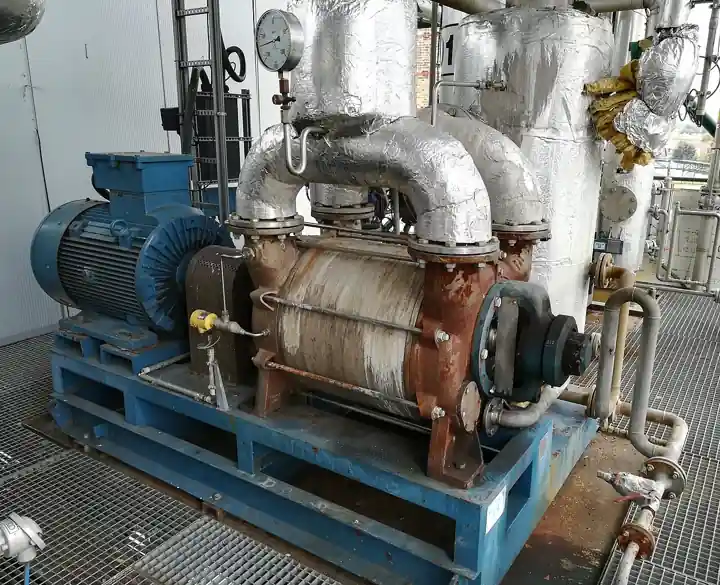
A Roots blower is a positive displacement air machine in which two lobed rotors, classically two-lobe figure-eight shapes and increasingly three-lobe or twisted helical profiles, counter-rotate inside a matching figure-eight casing without touching each other or the casing walls. Timing gears outside the gas stream hold the rotors in phase, the air path carries no oil, and every revolution moves a fixed volume of gas from inlet to discharge. The machine performs no internal compression: gas is delivered essentially at intake pressure, and pressure rises only when the discharge port opens against system backpressure. The practical single stage envelope runs from roughly 10 to 10000 m3/h at pressure rises of 10 to 1000 mbar gauge, and the same frames pull vacuum to about 500 mbar absolute. Body copy across the industry calls the same machine a Roots type blower or a rotary lobe blower, and this page uses those names interchangeably.
Procurement engineers meet these machines at wastewater treatment aeration basins feeding fine bubble diffuser grids, on dilute phase pneumaticconveying of flour, cement, and plastic pellets, at silo and bin fluidizing aeration pads, on vacuum trucks unloading septic and drilling fluids, and at fermentation vessels needing steady sparging air. The decision this page settles is narrow and practical: whether the duty point of required differential and required flow honestly sits inside the twin lobe envelope, which frame and rotor profile carry it continuously without overheating, and which drive, silencing, and protective hardware complete the station. The answer lands as an RFQ line set, flow and pressure at stated conditions, rotor configuration, drive arrangement, accessory list, and test data per ISO 1217, and every chapter below feeds that line set so the machine is bought against numbers rather than a brochure photograph.
This page treats the Roots blower as a purchasing object: how twin lobe displacement really behaves, what slip and discharge pulse do to sizing and piping, where the 1 bar ceiling and the 120 to 140 deg C thermal boundary come from, which construction options survive aeration and conveying duty, and how all of it combines into a defensible RFQ. It is written for engineers who issue purchase specifications, not for readers who want a brochure summary.
Chapter 1 / 06
What a Roots Blower Is and What Is Being Decided
The absence of internal compression is the defining fact. A screw compressor compresses gas inside its rotors before the discharge port opens; a twin lobe machine simply transports gas, and the moment the leading lobe clears the discharge port, the full system backpressure rushes back into the pocket and accelerates the gas in a sharp, nearly adiabatic jump. Two consequences follow. Absorbed power tracks the pressure differential, not the pressure ratio, so the machine does not care whether it pushes from 0 to 800 mbar or from 9200 to 10000 mbar absolute. And the compression heat of that jump lands entirely in the discharged gas, which is why discharge temperature, not motor rating, sets the real ceiling of the frame. Roots is a registered brand of Howden; the generic engineering terms rotary lobe blower and Roots type blower describe the construction this page is about.
What is actually being decided in this purchase is whether one frame can hold the duty point continuously, and the honest test is thermal, not nominal. A catalog maximum of 1000 mbar exists, but continuous duty at that differential pushes discharge temperatures toward 140 deg C, cooks gear oil, and erodes the running clearances that keep the lobes apart. The buyer commits to a frame, a rotor profile, a drive arrangement, and a protection package in one purchase order, each checkable on paper at RFQ stage: displacement per revolution against required flow, catalog slip at duty differential, discharge temperature at duty, and the accessory list that keeps a 20 year air end from becoming a five season one.
Against its neighbors, the twin lobe machine occupies deliberate ground, and the working comparison belongs in the selection chapter. As a pressure machine it sits between the regenerative blower, a side channel unit that is quieter and cheaper below roughly 300 mbar, and the screw compressor, which owns 3 to 10 bar with internal compression at higher cost. As a vacuum pump the twin lobe frame covers the rough band to about 500 mbar absolute, where the liquid ring vacuum pump takes wet gas and deeper vacuum duty and the rotary vane pump takes smaller flows with oil in the stream. The same lobe principle drives liquids in the lobe pump, a food and sanitary flow machine with liquid-tight clearances; the air machine shares its geometry and none of its sealing problems. The centrifugal pump and the dynamic fan world enter the comparison only at flows above what one lobe frame can reach.
Two data conventions organize the datasheet. Performance acceptance follows ISO 1217, the displacement compressor test standard, which fixes how displacement, flow, and power are measured and stated; a supplier quoting free air delivery without a test basis is quoting marketing. The Compressed Air and Gas Institute publishes a standardized CAGI data sheet format for blower packages, and two quotations filled out on that format can actually be compared line against line. Where the machine breathes dust or solvent vapor, ATEX or IECEx construction under the IEC 60079 series for the applicable zone is a line item, and the motor follows IEC 60034 rating practice with an IP54 or IP55 enclosure. A datasheet naming none of these is a price tag with a motor attached.
The RFQ should name the station, not just the air end. A complete blower station is an inlet filter with integral silencer, the blower itself, a discharge silencer, a safety relief valve set below the casing limit, a discharge check valve so a standby machine cannot be spun backwards by the running one, and instrumentation that proves the duty point: a pressure transmitter or at minimum a pressure gauge on discharge, and a flow switch or flow meter where process air accountability matters. Where the inlet breathes from a plant header instead of atmosphere, a Y strainer at the takeoff stops scale and weld debris that a panel filter was never designed to catch. Stating the whole station in the RFQ lets one supplier check relief settings, port sizes, and motor protection in a single pass instead of four arguments at commissioning.
Chapter 2 / 06
How the Twin Lobe Air End Moves Gas
Mechanically the air end is two rotors on parallel shafts, phased by hardened helical timing gears so the lobes pass each other with a standing clearance instead of contact. Running clearances live in the 0.1 to 0.4 mm class: rotor to rotor at the apex, rotor to casing at the tips and end plates. Those gaps are the whole engineering compromise of the machine. They must survive thermal growth from the discharge temperature jump, so a frame designed for 1000 mbar carries larger cold clearances than one designed for 300 mbar, and the larger clearance leaks more. The gas path is completely dry; gears and bearings sit in separate chambers behind labyrinth or lip seals.
Because each revolution sweeps a fixed rotor volume past the inlet, the machine is a true positive displacement device like a gear pump or a lobe pump handling liquid: displacement per revolution times speed sets theoretical flow, full stop. The difference from the liquid machines is that air is compressible and slippery, so internal leakage, called slip, runs backwards through every clearance from discharge to inlet. Slip rises with pressure differential and falls with speed, because faster rotation leaves less time for the same gap to leak. Volumetric efficiency in practice runs from roughly 85 percent at modest differential and healthy speed down to 60 percent near maximum differential at reduced speed. Sizing on displacement alone therefore undershoots the plant requirement at exactly the high differential points where undersizing hurts most; honest sizing subtracts catalog slip at the duty pressure before any margin is added.
The discharge event is a pulse, and pretending otherwise is how piping cracks. On a classic two-lobe machine each rotor delivers two pockets per revolution, so the discharge line sees four volume slugs per revolution and the pressure spike when each pocket opens against line pressure. A three-lobe rotor gives six smaller slugs per revolution at lower amplitude, and the twisted helical profiles marketed under names like WHISPAIR route the discharge plenum back to the trapped pocket through helical grooves, pre-charging it before the port opens so the shock wave is largely cancelled. The measurable results are roughly 10 dB(A) class noise reductions in some frames and materially lower pulsation loading on downstream piping, the difference between quiet commissioning and a fatigue failure on thin-wall ducting.
Power and temperature behavior follow directly from the no-compression principle. Absorbed brake power is roughly proportional to differential times flow, with an adiabatic pulse heating term added at the port opening, so discharge temperature can be estimated as intake temperature plus a rise that scales with differential: 500 mbar across a 20 deg C inlet commonly lands near 85 to 95 deg C discharge, and 800 to 1000 mbar sustained pushes 120 to 140 deg C, the continuous limit for most standard frames because beyond it thermal growth eats the clearances and the gear oil film oxidizes. The machine is therefore safest at the bottom of its pressure range and most fragile at the top, the exact opposite of a centrifugal pump or fan, whose power rises with flow instead of with differential. Intercooling between two machines in series is the standard answer above the single stage thermal ceiling.
Speed control is the instrument that makes the machine economical on varying duty. Because flow is proportional to speed and differential is set by the system, a VFD trimming blower speed against aeration demand tracks the diurnal oxygen curve directly, and the cube-law savings of dynamic machines do not apply but the proportional flow savings do: an aeration basin at 60 percent of daytime oxygen demand needs 60 percent of daytime air, and a machine throttled by speed runs cooler and quieter than one spill-gating surplus air. Belt drives give a cheap fixed ratio; direct drive with a coupling removes belt losses and maintenance; direct drive plus a VFD is the configuration most wastewater plants now buy, because the blower is the largest energy consumer on site.
Chapter 3 / 06
Types, Construction, and Duty Boundaries
Three rotor families cover the catalogs. The classic bi-lobe rotor, two full figure-eight lobes, is the historical workhorse: simplest to cast and machine, tolerant of thermal growth, but with the four-pulse-per-revolution signature described in chapter 2. The straight tri-lobe rotor trades slightly less displacement per revolution for six smaller pulses and lower noise, at home in blower rooms near occupied spaces. The twisted helical tri-lobe, the WHISPAIR class construction with its inlet plenum and helical grooves, is the current premium answer for noise and pulsation sensitive duty, at a price premium and a narrower stable operating map on some frames. All three remain dry machines with externally lubricated timing gears; the rotor choice is a noise, pulsation, and cost decision, not an oil-free decision.
Casing and mounting architecture varies more than datasheets admit. Flanged horizontal or vertical inlet and discharge orientations decide how the station pipes up in a cramped blower room; cast iron housings are standard, with aluminum casings on smaller frames for weight; water-jacketed or air-cooled finned housings appear on high differential frames to hold casing temperatures down. Shaft sealing runs from labyrinth seals, which leak nothing inboard but let a whiff of air outboard, to double lip seals or buffered mechanical seals where any gear oil mist in the air stream would contaminate the process, the concern in fermentation sparging and food conveying. Drive end options pair the air end with a V-belt sheave set or a direct coupled motor on a common base; gas-tight and submersible motor variants exist for biogas duty where hydrogen sulfide makes the blower room atmosphere itself corrosive.
Lubrication is a small line with warranty consequences. Splash lubrication, gears dipping in an oil sump, is simple and standard on horizontal frames, with oil changes at roughly 2000 to 8000 operating hours depending on duty temperature. Grease-lubricated bearings suit vertical shaft machines and high temperature frames where an oil sump would not stay put. The failure to plan for is the seal between lubricated and dry zones: a worn shaft seal lets oil mist into the discharge air, first as a smell, later as a contamination complaint. Where the air contacts food or cell culture, the RFQ should state the allowable oil carryover and the seal type that enforces it.
Duty boundaries deserve blunt statement. Single stage continuous pressure rise is honest up to about 800 mbar with a catalog maximum near 1000 mbar; two machines in series with intercooling extend the range toward 2 bar class. Vacuum duty to roughly 500 mbar absolute is standard with an inlet silencer and inlet buffering; deeper vacuum belongs to the liquid ring vacuum pump or rotary vane families. Flow per frame runs from the smallest positive displacement units near 10 m3/h to the largest cast frames near 10000 m3/h; above that, or anywhere the required differential is under about 200 mbar, the side channel machine or a fan class answer is usually cheaper per cubic meter, and laboratory scale air below roughly 20 m3/h is more honestly served by a diaphragm pump than by the smallest rotary frame. Intermittent ratings exist on paper for startup and blowdown transients only; a buyer who schedules an intermittent rating for daily duty is buying the next air end.
The table below consolidates the construction decisions into the form a specifier can scan before writing the RFQ.
Construction option
What it buys
Duty boundary and trade
Bi-lobe rotors, splash lube
Lowest cost, thermal tolerance, simple spares
Four pulses per revolution; noise treatment needed near occupied areas
Straight tri-lobe rotors
Six smaller pulses, roughly 5 to 10 dB(A) quieter
Slightly less displacement per revolution; higher price
Belt losses 2 to 4 percent; tensioning maintenance
Direct drive with coupling
No belt maintenance, best efficiency
Speed fixed by motor unless driven by a VFD
Water-jacketed casing
Higher continuous differential on a given frame
Needs plant cooling water and winter protection
Two machines in series, intercooled
Pressure rise toward 2 bar class
Two air ends, intercooler, doubled maintenance surface
Chapter 4 / 06
Key Specification Parameters
The table below decodes the datasheet lines that decide whether a quoted frame matches the service. Each row is a purchase defining parameter; the paragraphs after the table explain what to demand and what a weak answer looks like.
Attribute
Typical range or options
What it decides
Nominal flow capacity
10 to 10000 m3/h per frame, free air at reference conditions
Frame family and how many machines the station needs
Rated pressure rise
10 to 800 mbar continuous, about 1000 mbar catalog maximum single stage
Discharge temperature, clearance class, and whether staging is needed
Vacuum capability
to roughly 500 mbar absolute single stage with inlet buffering
Whether the frame covers truck unloading and rough vacuum duty
Discharge temperature limit
120 to 140 deg C continuous on standard frames
The real ceiling of the frame; every other rating bends under it
Running clearances
0.1 to 0.4 mm class, rotor to rotor and rotor to casing
Slip, volumetric efficiency, and tolerance of thermal growth
Pulse count, noise, pulsation loading on downstream piping
Lubrication
Splash oil sump, grease bearings, change intervals 2000 to 8000 h
Maintenance load and oil mist control at the shaft seals
Shaft power and drive
0.75 to 500 kW class; V-belt, direct coupling, VFD direct
Motor frame, electrical supply, and energy tracking on varying duty
Noise declaration
Typical 70 to 95 dB(A) at 1 m before silencing treatment
Blower room design and whether an enclosure is mandatory
Acceptance test basis
ISO 1217 displacement machine test; CAGI data sheet format
Comparability of two quotations line against line
The flow row is the one most often misread, because three different numbers wear the same name. Displacement per revolution times speed is theoretical flow, which no plant ever receives. Free air delivery at the duty point is displacement minus slip at that differential, the number the process actually needs. And inlet volume at actual suction conditions shifts with altitude and inlet restriction, which is why ISO 1217 exists: it fixes reference conditions so that a 5000 m3/h claim from two suppliers means the same thing. Demand the duty point flow on a stated test basis, and demand the slip curve against differential, because that curve determines whether the frame holds your flow on the hottest day against the dirtiest filter.
The temperature row deserves equal attention because it silently governs the pressure row. Ask for discharge temperature at maximum continuous differential, not at the sweet spot, and check the answer against the process: flour and polymer conveying degrade above roughly 90 to 100 deg C, diffuser membranes and PVC pipe headers have their own limits, and O-ring sealed downstream hardware usually caps at 120 deg C class. Where the process ceiling is tighter than the machine ceiling, the honest fixes are a larger frame at lower differential per stage, an aftercooler on the discharge line, or two machines in series with intercooling. Buying on the machine ceiling alone and discovering the product ceiling at commissioning is expensive.
The comparison table below places the twin lobe machine against the neighboring air and vacuum families in the numbers that matter to a buyer, so the envelope decision can be made before any brand conversation starts.
Machine family
Pressure band
Flow band
Air path and character
Roots type twin lobe blower
10 to 1000 mbar rise; 500 mbar abs vacuum
10 to 10000 m3/h
Dry, pulsating, power tracks differential
Side channel regenerative machine
to roughly 300 mbar
30 to 2500 m3/h
Dry, quieter, steep unstable curve at the top
Oil injected screw compressor
3 to 10 bar
hundreds to tens of thousands m3/h
Internal compression, oil in stream, higher cost
Liquid ring machine
vacuum to about 30 mbar abs
tens to thousands m3/h
Wet, tolerant of condensate and solvents
Rotary vane machine
vacuum and pressure to about 2 bar
small to medium flows
Oil lubricated vanes, oil carryover to manage
Centrifugal fan class
to roughly 100 mbar
very large flows
Dynamic, quiet, surge and stall boundaries
Read the table as boundaries, not rankings. The twin lobe machine wins where differential is 200 to 1000 mbar, flow is moderate, the air must be oil free, and the demand varies enough to reward speed control. Each neighbor owns a band the lobe machine reaches only at its weakest edge, which is why the envelope check belongs at the start of the specification.
Chapter 5 / 06
Selection Decision Factors and RFQ Language
The decision sequence is short enough to run as a checklist in a specification meeting, and each step eliminates a class of quotations before price comparisons begin.
Fix the duty point honestly: required flow in m3/h free air, required differential in mbar, at worst case inlet temperature and dirty filter condition, not at reference conditions flattered by clean air.
Check the envelope against the family table in chapter 4: below about 200 mbar the side channel machine is usually cheaper and quieter; above 1000 mbar sustained the screw machine or staging wins.
Compute discharge temperature at the duty differential and compare it against the process ceiling, product sensitivity, diffuser membranes, piping and seals, not just the machine limit.
Size on displacement minus slip: demand the volumetric efficiency curve and confirm the frame delivers duty flow with speed margin left for filter loading and future demand.
Choose the rotor profile on noise and pulsation evidence, a declared dB(A) figure and pulse count, not on a marketing adjective like quiet series.
Choose the drive: V-belt for a fixed cheap ratio, direct drive for efficiency, direct drive with a VFD where aeration or process demand swings through the day.
Specify the station hardware: inlet filter silencer, discharge silencer, safety relief valve set under the frame limit, discharge check valve, drain management on any intercooler, and a downstream FRL unit where the air feeds cylinders and instruments.
Fix the evidence: ISO 1217 test basis or CAGI data sheet, noise declaration, discharge temperature at maximum differential, and material certificates where the gas is corrosive.
Against neighboring technologies the comparison runs as follows, and it belongs here in the selection chapter rather than in the page title. The regenerative blower is the side channel machine: quieter, lighter, and cheaper below about 300 mbar, but its flow is modest and its steep curve punishes any system resistance growth. The screw compressor owns 3 to 10 bar with internal compression, so it does the work at a fraction of the discharge temperature, but the oil injected versions put oil in the air stream and the oil free versions cost several times a lobe frame. As a vacuum pump the lobe machine covers rough vacuum to about 500 mbar absolute; the liquid ring vacuum pump goes deeper and eats condensate that would corrode a dry lobe machine, and the rotary vane pump goes deeper still on small flows but puts oil in the stream. Where the duty moves liquid rather than gas, the same geometry question is settled by a lobe pump or a gear pump, not by an air machine; and where flow requirements are tiny and intermittent, a diaphragm pump metering air into a process is a simpler instrument than any rotary frame.
Application mapping turns the comparison into project language. Wastewater aeration is the anchor duty: fine bubble diffusers at 3 to 5 m submergence plus distribution losses and filter drop usually demand 300 to 800 mbar, solidly twin lobe territory, and the diurnal oxygen curve rewards a VFD on at least the lead machine. Dilute phase conveying of flour, sugar, and plastic pellet runs on the same pressure class with rotary valves feeding the line, where pulse amplitude decides whether the elbows survive. Silo fluidizing aeration is a low differential, wide zone duty that often suits a smaller tri-lobe frame. Vacuum truck unloading pulls the same frame as an inlet machine with buffering and a liquid trap. Fermentation sparging demands steady oil free air at modest pressure, where shaft seal quality matters more than any other line on the datasheet.
Application
Construction to specify
Check before order
Wastewater fine bubble aeration
Tri-lobe or twisted helical frame, direct drive with VFD, inlet filter silencer
Discharge temperature at 800 mbar class duty; diffuser grid submergence math
Liquid carryover protection; relief and vacuum break settings
Fermentation sparging air
Oil free frame with buffered shaft seals, afterfilter, standby machine
Oil carryover statement; sterile filter pressure drop budget
Biogas and landfill gas boosting
Gas-tight casing, corrosion resistant rotors, ATEX zone rated motor
Gas analysis against material selection; seal gas scheme
The RFQ block should be written once and reused. A complete block reads: quantity and duty rating, continuous or intermittent; required flow in m3/h free air and required differential in mbar at stated inlet temperature and altitude; inlet condition, atmospheric or header fed with a Y strainer at the takeoff; rotor configuration and casing construction; discharge temperature at maximum continuous differential; drive arrangement, motor rating, enclosure, and whether a VFD supplies the machine; accessory list, inlet filter silencer, discharge silencer, safety relief valve with set pressure, discharge check valve, and instrumentation, a pressure transmitter on discharge, a pressure gauge at the skid edge, and a flow meter or flow switch where air accountability is audited; acceptance per ISO 1217 with results on the CAGI data sheet format; noise declaration for the complete package; and the material and coating schedule for corrosive gas. A quotation returned without the slip curve or the discharge temperature at duty is incomplete at any price.
Chapter 6 / 06
Installation, Standards, Failure Modes, and Maintenance
Installation quality decides whether the air end reaches its 20 year design life. Start with the foundation: a rigid pad massing several times the machine weight, because a pulsating positive displacement frame shakes whatever is underdesigned. Pipe the discharge in heavy wall ducting with supports close to the machine, and give the line a flexible section at the flange so thermal growth and piping strain do not load the casing; pulsation fatigue of elbows is the signature failure of ignored discharge pulses. Never throttle the discharge to control flow, and never start the machine against a closed discharge valve: a gate valve used for isolation must be open, or open on a timed bypass, before the motor is energized, because a deadheaded blower climbs to relief pressure in seconds while its discharge temperature runs away. The safety relief valve between blower and any isolating valve is not optional hardware, and its set pressure belongs in the commissioning record.
Inlet conditioning is the other half of the installation. The inlet filter silencer protects the clearances described in chapter 2, and its pressure drop is part of the duty point: an inlet restriction lowers inlet density, so the same frame delivers less free air, and a blinded filter is functionally an undersized blower. Where the machine feeds a pneumatic conveying loop, a Y strainer or cyclone ahead of the inlet catches product fines on vacuum duty. Downstream of the machine, keep the oil free promise intact where the air feeds sensitive equipment: a filter regulator, or a full FRL unit where the air works cylinders and tools, polishes residual particulate and sets point of use pressure. Instrument the station so it can be trusted: a pressure transmitter or pressure gauge on discharge against the duty point, a discharge temperature sensor with an alarm at the frame limit, a flow switch proving air delivery on processes where silence means spoilage, and a vibration sensor on machines above 100 kW.
The standards frame is compact. ISO 1217 governs how displacement, flow, and power are tested and stated for acceptance. CAGI data sheet practice makes two supplier packages comparable line against line, and asking for it in the RFQ is free. Motors and enclosures follow IEC 60034, and hazardous atmosphere machines carry ATEX or IECEx certification under the IEC 60079 series, with the zone stated by the buyer, not assumed by the seller. Noise declarations for the complete installed package, not the bare air end, are what a permitting authority will ask for. There is no API standard governing generic aeration blowers; the honest substitute is the ISO 1217 acceptance test plus the mechanical checklist in this chapter.
Failure modes in service follow a short and predictable list. Rotor contact: misalignment, bearing failure, or foreign object ingestion closes the 0.1 to 0.4 mm clearances, announced by rising clatter then casing scoring; prevention is inlet filtration and alignment records, and the cure is an air end rebuild. Gear and bearing wear: backlash opens, timing drifts, slip rises, and flow falls a few percent a year until the process complains; a vibration trend catches it a season before failure. Overheating from deadheading or blocked discharge: discharge temperature spikes, clearances close thermally, and the machine can seize mid-clatter; the relief valve and the temperature trip are the two devices that prevent it, and both must be tested on a schedule. Oil seal leakage: gear oil mist appears in the discharge air, a process contamination complaint on food and fermentation duty, cured by seal replacement before the smell becomes a rejection. Pulsation fatigue: cracks at discharge elbows and silencer internals, prevented only by correct piping practice at installation.
Maintenance intervals scale with duty severity. Standard practice on splash lubricated frames is oil analysis or change at 2000 to 8000 hours depending on discharge temperature class, with grease bearings regreased on the maker interval and never overfilled. Belt drives need tension and sheave checks quarterly; direct drives trade that for coupling alignment checks at every intervention. The relief valve gets a lift test annually, the inlet filter element is replaced on pressure drop, not calendar, and the discharge temperature alarm is proven yearly. Every intervention should record clearance figures, vibration readings, and oil results in the same file as the ISO 1217 acceptance data, because that file turns the next RFQ from a guess into a specification.
FAQ
How much pressure can a single stage Roots blower actually make?
A single stage twin lobe machine in continuous duty works best between roughly 200 and 800 mbar of pressure rise, and most catalogs quote a maximum near 1000 mbar gauge. There is no internal compression, so the full pressure develops at the discharge port and discharge temperature climbs with differential toward the 120 to 140 deg C continuous limit. Above sustained 1000 mbar duty, two machines in series with intercooling or a screw machine is the correct engineering answer.
Does a Roots blower put oil into the air stream?
No. The air path is dry: only the rotors and casing contact the gas, and the timing gears and bearings run in separate oil or grease lubricated chambers behind labyrinth or lip seals. Small amounts of oil mist can migrate past worn shaft seals on high hour machines, which matters for fermentation sparging and food conveying, so seal condition belongs in the maintenance file. The delivered air is called technically oil free, though it is not validated oil free the way instrument class supply is.
What is slip and how does it change sizing?
Slip is internal leakage backwards through the rotor clearances, typically 0.1 to 0.4 mm wide, and it rises with pressure differential while falling with rotor speed. A frame sized on displacement per revolution alone will undershoot the required free air delivery exactly at high differential, where undersizing hurts most. Honest sizing subtracts catalog slip at duty pressure, then adds margin: dividing required flow by a realistic volumetric efficiency, often 60 to 85 percent at the duty point, gives the displacement the RFQ must demand.
Should I buy a twin lobe machine or a side channel machine for aeration?
Let the required pressure decide. Fine bubble diffuser grids at 3 to 5 m submergence, plus distribution losses and dirty filter drop, usually demand 300 to 800 mbar, which is twin lobe territory. Below roughly 200 mbar, on shallow tanks and small hold down duties, the side channel regenerative machine is quieter, lighter, and usually cheaper. Above about 1000 mbar sustained, or when one machine must exceed roughly 10,000 m3/h, staged blowers or a screw machine take over.
How hot does the discharge air get?
Because compression happens instantly when the discharge port opens, outlet temperature tracks pressure differential more than anything else. Typical figures are 80 to 95 deg C at 500 mbar duty from a 20 deg C inlet, rising to 140 deg C at 1000 mbar, the continuous ceiling of most standard frames. Product sensitivity can cap it lower: flour and polymer conveying degrade above roughly 90 to 100 deg C, so a larger frame at lower differential, or an aftercooler, is the honest fix.
Can a Roots blower be used as a vacuum pump?
Yes, the same frames run as inlet machines. Single stage duty reaches roughly 500 mbar absolute with proper inlet buffering, a silencer, and a trap for any liquid carryover on truck unloading duty. Deeper vacuum is the territory of the liquid ring machine, which tolerates condensate and solvents that would corrode a dry lobe machine, or of vane and screw machines on their respective bands. On vacuum duty the higher inlet density at startup loads the motor, so size the motor for the startup case, not the endpoint.
What accessories must a complete blower RFQ include?
The station, not just the air end: an inlet filter with integral silencer, a discharge silencer, a safety relief valve set below the casing limit, a discharge check valve on every duplex machine, and instrumentation: a pressure transmitter on discharge, a discharge temperature alarm, and a flow switch or flow meter where air delivery is audited. State the drive, whether a VFD supplies the motor, acceptance per ISO 1217, and a package noise declaration. A quotation missing the slip curve or duty temperature is incomplete.