A cooling tower is a wet heat rejection device that cools a circulating water stream by spreading it over fill while air moves through, so that a small fraction of the water evaporates and carries latent heat away to atmosphere. Each kilogram evaporated removes roughly 2.4 MJ, which is why an evaporative cooling tower rejects large duties with modest water loss: at the 8 to 11 deg C ranges common in industrial service, about 1.5 to 2 percent of the circulated flow leaves as vapor, with blowdown and drift added on top for the water balance. Called a cooling water tower on many operating sites, it is the hardware that closes a plant heat balance at the wet bulb temperature of the local climate rather than the dry bulb, which is the entire basis of its efficiency advantage.
Procurement engineers meet these towers on chiller condenser water loops in commercial and data center plants, on engine jacket water and compressor cooling, and on the utility circulating water systems of steel, chemical, and power installations. The decision this page settles is narrow and practical: whether wet heat rejection fits the site at all, which draft and flow configuration and fill construction survive the water quality, how the tower is sized in range, approach, and design wet bulb terms, and what the RFQ must state about certification, sound, and winterization so that competing quotations compare on equal terms. The answer lands as an RFQ line set, and every chapter below feeds that line set.
This page treats the cooling tower as a purchasing object: how range, approach, and design wet bulb define the selection point, what induced and forced draft and crossflow and counterflow construction actually change, what fill, drift eliminators, and materials survive which water, how the water chemistry program and its instruments keep the machine alive, and how CTI certification, sound limits, and winterization combine into a defensible RFQ. It is written for engineers who issue purchase specifications, not for readers who want a brochure summary.
Chapter 1 / 06
What a Cooling Tower Is and What Is Being Decided
The purchase is bigger than a box with a fan. A factory assembled cooling tower arrives as a casing structure of fiberglass reinforced polyester or galvanized or stainless steel, a cold water basin, a fill section where air and water meet, a hot water distribution system, drift eliminators above the fill, one or more axial fans with their drives, ladders, platforms, and the louvers or casings that shape the airflow. Field erected cells carry the same elements at larger scale in banked modular arrangements. The sizing language of the whole purchase is four numbers: circulating flow, range, approach, and design wet bulb, and every thermal claim in every quotation is conditional on those four numbers being stated identically to every bidder.
What is actually being decided in this purchase is five commitments at once. First the configuration: induced or forced draft, crossflow or counterflow, open circuit or closed circuit coil construction. Second the thermal sizing point: range and approach against a design wet bulb chosen on an exceedance basis, which is a first cost argument, not a meteorology fact. Third the materials plan: galvanized steel is the economy answer, stainless steel and pultruded FRP structure are the corrosion answers, and the choice is decided by water chemistry and tower life, not by catalogue photography. Fourth the water chemistry program: cycles of concentration, blowdown control, biocide dosing, and scale and corrosion inhibition, because an untreated tower is a fouling machine that destroys its own fill within a few seasons. Fifth the site package: sound at the property line, freeze protection, and the coordination of basin heaters, bypass lines, and fan control for winter.
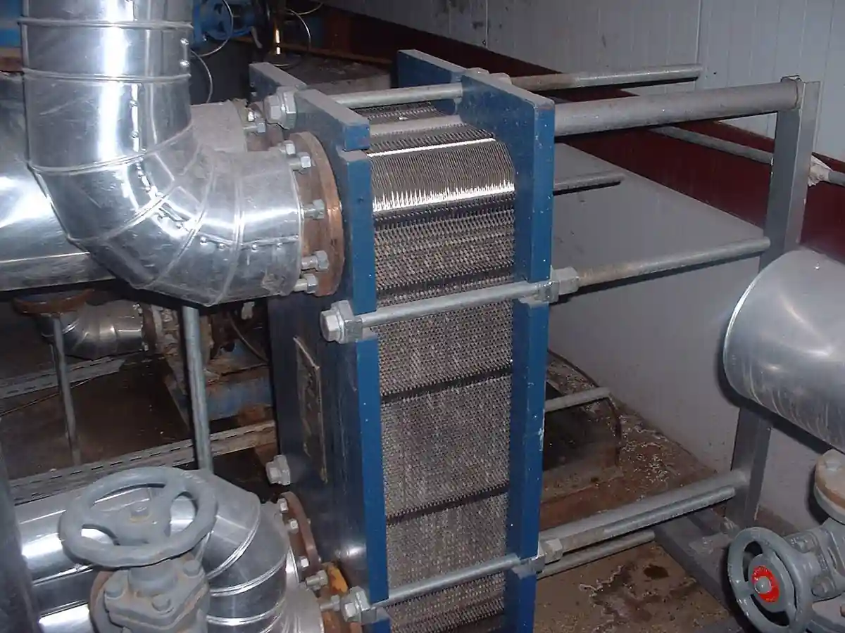
The boundary against the neighbors is worth drawing early, with the full comparison reserved for the selection chapter. A chiller is the instrument for below ambient cooling, and the wet tower is not: cold water leaving a tower can never be colder than the entering air wet bulb, and realistic designs settle 3 to 8 deg C above it. An air-cooled heat exchanger rejects heat without consuming water, bounded instead by the dry bulb temperature with honest approaches of 10 to 15 deg C, and it wins arid sites where the tower's evaporation and blowdown cannot be supplied or permitted. Inside the plant water circuit, a shell and tube heat exchanger transfers process heat into the circulating water loop on its way to the tower, and a plate heat exchanger isolates a dirty or critical process stream from the open cooling circuit at close approach. Those two are liquid to liquid machines; the cooling tower is the only element in the station that rejects heat to atmosphere, and the RFQ should keep that division of labor explicit so no vendor sells a heat exchanger as a heat rejection device.
Four documents organize the datasheet. CTI STD-201 is the Cooling Technology Institute certification standard under which manufacturers publish thermal capabilities verified by CTI sponsored testing, and buying a certified line means the published curve has been audited rather than asserted. CTI ATC-105 is the field acceptance test code under which an installed tower is tested, hot water temperature, cold water temperature, wet bulb, and flow measured simultaneously, and its results compared against the certified capability curve. ASHRAE 90.1 sets the energy context, including fan power budgeting discipline for heat rejection equipment. Piping to and from the tower follows ASME B31.9 for building services or the process piping code the site applies, and local noise ordinances frame the sound clause. A datasheet that quotes none of these is a price tag, not a specification.
The tower never works alone, and the RFQ should name its station. Circulated water is moved by a dedicated pump per cell or per bank, typically a centrifugal pump selected on flow and modest head, with the tower basin providing suction. Isolation at each cell is usually a butterfly valve sized for low pressure drop, because these are large lines and head is money. Commissioning protection is a strainer story: weld bead and construction scale lodge in spray nozzles and fill during first circulation, and a temporary Y strainer with a coarse insert is cheaper than a nozzle rebuild. Instrumentation is part of the purchase, cold basin temperature for fan control, makeup and blowdown metering, and the chemistry sensors of chapter 4, and stating the whole station in the RFQ lets one supplier check nozzles, valves, and instrument mounts in a single pass.
Chapter 2 / 06
How Evaporation and Wet Bulb Physics Set the Design
The physics is evaporative cooling against the wet bulb. Air entering the tower carries moisture and enthalpy; water falling through the fill spreads into films and droplets with an enormous transfer area; and at the water surface the air is saturated at the water temperature. Heat moves from water to air as sensible transfer across the temperature difference and as mass transfer across the vapor pressure difference, and the two couple through the latent heat of evaporation. The limiting state is the thermodynamic wet bulb: the temperature at which water cools by evaporation until the air leaving is saturated and no further driving force exists. That is why the design wet bulb, not the dry bulb, is the climate number the entire selection hangs on, and why the approach, cold water temperature minus wet bulb, is the true measure of how hard the tower is working.
Approach economics deserve their own warning because they are nonlinear. Approaches of 3 to 8 deg C cover most honest industrial selections, and each degree closer to the wet bulb buys exponentially more fill depth, airflow, fan power, and footprint. A 3 deg C approach is achievable and is bought only where process economics pay for it, condenser vacuum improvement on a steam machine, chiller efficiency on a critical comfort or data load. Below about 3 deg C the tower stops being a reasonable machine and the correct instrument for tighter temperatures is upstream refrigeration. In words, the tower characteristic is expressed in the industry as the transfer coefficient times the fill area per unit of water flow, set against the air to water mass ratio: the two ratios are tuned together until the exit air and exit water states close the enthalpy balance, and the water to air mass flow ratio in mechanical draft towers lands typically between 0.75 and 1.5.
The water balance is arithmetic the buyer should run before the first RFQ. Evaporation runs close to 0.18 percent of the circulated flow per deg C of range, so a 6 deg C range evaporates about 1 percent of circulation and the 8 to 11 deg C industrial ranges evaporate 1.5 to 2 percent. Makeup equals evaporation plus blowdown plus drift. Blowdown is set by the cycles of concentration the chemistry program allows, the ratio of dissolved solids in the circulating water to those in the makeup, and blowdown equals evaporation divided by cycles minus one. A worked example fixes the magnitudes: 1,000 m3/h circulation at 8 deg C range evaporates about 14 m3/h, and at 5 cycles of concentration the blowdown is 3.5 m3/h, so makeup is roughly 18 m3/h plus drift. Drift, water carried out as liquid droplets rather than vapor, is controlled by eliminators to about 0.001 percent of circulated flow on current designs, negligible in the balance but decisive in the plume and Legionella management discussion. The blowdown setpoint is not a guess: it is held by a conductivity meter on the basin or blowdown line opening the blowdown valve whenever circulating conductivity exceeds the setpoint implied by the cycles target and the makeup water analysis.
Hydraulics set the pump budget, and configuration sets the hydraulics. A counterflow tower distributes hot water through pressurized spray nozzles, which wants 5 to 10 m of head at the header, while a crossflow tower feeds gravity basins above the fill and runs on 2 to 4 m. The circulating service is a straightforward centrifugal pump duty per cell, cast iron with stainless or bronze trim on treated water, and on tall plants or remote headers the return leg may be served by a multistage pump where static lift and long runs demand the extra stages. Suction design deserves a line of its own: the basin is the pump suction source, vortex suppression and minimum submergence over the outlet are part of the tower specification, and every meter of avoidable head is fan and pump energy spent for the life of the plant.
Fans convert electric power into airflow, and their budget is a selection variable. Axial fans on mechanical draft towers run roughly 2 to 10 m diameter with tip speeds held in the 60 to 75 m/s class for acoustic and structural reasons, and total fan power at design lands typically between 1.5 and 3 percent of the rejected thermal duty. Capacity control therefore lives on the fan first: a variable frequency drive on each fan trims speed to hold cold basin temperature against load and weather, a temperature transmitter in the cold basin or outlet line closes that loop, and two speed motors remain the economy alternative where drive budgets are tight. On the water side, a bypass control valve that routes hot water directly to the basin at start-up and in deep part load prevents overcooling and fill shock, and in freezing climates it is a core element of winter operation rather than an accessory.
Two consequences of the physics close the chapter. Recirculation: discharge air is hot and humid, and a tower sited too close to a wall, a neighboring cell, or its own structure swallows its own exhaust, raising the effective inlet wet bulb and stealing capacity exactly on peak days, which is why siting clearance belongs in the purchase specification. Plume and drift: the visible plume is condensed water vapor and is mostly an aesthetic and icing concern near roads, while drift is liquid water carrying treatment chemicals and bacteria with it, which is why eliminator condition, not just eliminators, is a maintenance line item in chapter 6.
Chapter 3 / 06
Draft Types, Fill Construction, and Duty Boundaries
Draft configuration is the first construction commitment. In an induced draft tower the fan sits at the top of the unit in the discharge position and pulls air through the fill, so the casing below runs at slight negative pressure, air distribution through the fill is uniform, exit velocity defeats recirculation, and the plume leaves from the highest point. The drivetrain works in warm humid exit air, which costs bearing life and access effort, and the structure carries the fans at the top. In a forced draft tower the fans sit at the base and push air through the fill, the casing runs pressurized, and the fans, motors, and drives live at grade in cool air where maintenance is cheap; the trade is less uniform air distribution, higher recirculation exposure at the low discharge point, and icing risk on the fan itself in freezing weather because the fan sees cold entering air with it loaded with moisture. The established factory assembled lines, such as the induced draft counterflow and crossflow families in the sources, publish both configurations, and the choice is usually settled by plot, sound, and winter climate rather than by thermal capability.
The second commitment is flow direction through the fill. In a crossflow tower, hot water flows by gravity out of basins mounted along the sides, falls through fill that air crosses horizontally, and the pump head is minimal because distribution is open to atmosphere. Gravity basins are inspectable and adjustable, and the arrangement tolerates wide flow turndown; the exposure is debris and sunlight in the open basins, which invites algae and trash. In a counterflow tower, hot water is pumped to spray nozzles above the fill and air moves upward against the falling water, giving a compact footprint, higher transfer efficiency per cubic metre of fill, and pressurized distribution that stays clean, at the price of pump head and nozzle maintenance. The table below compresses both commitments.
Configuration
Air and water arrangement
Strengths
Watch items
Induced draft counterflow
Fan on top pulls air up through spray and fill
Uniform airflow, compact footprint, recirculation resistant, highest efficiency per m3 of fill
Drivetrain in warm humid air at height, pressurized spray nozzles to maintain
Induced draft crossflow
Fan on top, gravity hot water basins on the sides, air crosses the falling film
Low pump head, inspectable basins, wide turndown on water flow
Open basins collect debris and sunlight, larger footprint per cell
Forced draft
Fans at the base push air through the fill
Grade level maintenance, cooler air at bearings, lower structure cost
Recirculation exposure, icing on fans in freezing climates, less uniform distribution
Closed circuit cooler
Spray water over a serpentine coil, process fluid stays inside the tube
Clean closed process loop, no fouling exposure of process fluid
Coil cost and freeze exposure, dry duty derate, higher first cost per kW
Fill is the heat transfer surface, and water quality decides its type. Film fill, vacuum formed PVC packs with closely spaced corrugated sheets that spread water into thin films, 0.3 to 1.8 m deep in the common designs, is the efficiency standard for clean treated water, and its fine passages are exactly what scale and suspended solids plug. Splash fill, bars or grids that break the stream into droplets, sacrifices transfer efficiency for tolerance: dirty water, high suspended solids, and poor chemistry control are splash territory, and the depth of fill required grows accordingly. Between them sit high efficiency film fills with wider openings sold for marginally dirtier duty. The drift eliminator above the fill, woven or cellular PVC blades that force the leaving air to turn and drop its liquid burden, is specified to a drift rate class, with 0.001 percent of circulating flow the current standard and lower classes available near sensitive sites.
Structure and drives finish the hardware. Factory assembled casings are fiberglass reinforced polyester or galvanized steel, with stainless steel construction and pultruded FRP structural profiles offered for corrosive and coastal sites, and stainless fasteners specified wherever galvanic pairs would otherwise eat the panel seams. Cells are modular: factory assembled lines cover roughly 50 to 1,000 m3/h circulation per cell, larger field erected counterflow and crossflow cells serve 2,000 to more than 5,000 m3/h each, and multiple cells are banked in parallel against the plant load with isolation so single cells come off line for service. Fan drives are either belt packs, economy and simpler maintenance with a service life measured in years, or right angle gear drives, higher first cost and oil sampling discipline in exchange for durability on large fans, and each fan may carry a variable frequency drive for capacity and sound control.
The basin is an engineered element, not a tub. The cold basin holds the working volume, typically on the order of one to three minutes of circulated flow at operating level, deeper where winter storage and heater placement matter. Makeup enters through a float operated valve or a level controller on a metered make up line, and the overflow and cleanout arrangements decide whether the basin silts or drains properly. Side stream filtration is the standard discipline for open circuits: 5 to 10 percent of circulation bled through a sand, disc, or screen filter catches the suspended solids that would otherwise settle in the basin and lodge in fill, and the filter loop is a small pump and valving package that belongs in the tower purchase, not in a later change order.
Winterization is a construction package, not a startup trick. Basin heaters, steam coils or electric immersion heaters sized to hold basin temperature above freezing with fans off, keep the stored volume liquid, and each steam coil discharges condensate through a steam trap at the low point that must itself be maintained or the coil floods and freezes. Deep part load and freeze protection use the hot water bypass control valve to route water directly to the basin, fan control to shut or reverse cells, and damper or louver arrangements on some designs. Freeze protection of makeup lines and small bore piping, trace heating and drainage, is a site package that the RFQ should name rather than assume.
Chapter 4 / 06
Key Specification Parameters
The table below decodes the datasheet lines that decide whether a quoted tower matches the duty. Each row is purchase defining; the paragraphs after it explain what to demand and what a weak answer looks like.
Parameter
Typical range or decision
What it decides
Circulating flow
50 to 5,000+ m3/h per cell, banked in parallel
Cell count, nozzle and pipe sizing, pump selection
Range
5 to 20 deg C family, 8 to 11 deg C common industrial
Evaporation load, fill depth, and approach interaction
Approach
3 to 8 deg C, cost rises steeply near 3
Feasibility of the cold water temperature and machine size
Design wet bulb
1 percent exceedance value for the site
The thermal honesty of every other number in the quotation
Draft and flow configuration
Induced or forced, crossflow or counterflow, open or closed circuit
Plot shape, pump head, recirculation and icing exposure
Fill and eliminators
Film PVC 0.3 to 1.8 m, splash for dirty water, drift to 0.001 percent
Thermal efficiency, water quality tolerance, plume water loss
Materials
Galvanized, SS304 or SS316, pultruded FRP structure
Corrosion life against water chemistry and coastal air
Fan power and control
1.5 to 3 percent of duty at design, VFD per fan
Energy budget, sound at part load, capacity turndown
Sound
60 to 75 dBA class at the property line by site rule
Fan speed, blade count, cell count, and enclosure options
Basin and water side
Float makeup, side stream filtration 5 to 10 percent of flow
Solids discipline and the chemistry program's hardware
Certification
CTI STD-201 certified performance, ATC-105 field test option
Whether the published thermal curve has been audited
The design wet bulb row deserves its own paragraph because it is the row most often fudged. Every thermal number in a quotation is conditional on the stated wet bulb, so a vendor quoting at a 25 deg C design wet bulb against a competitor quoting at 28 deg C is not quoting the same machine, and the cheaper quotation may simply be assuming cooler air. Fix the design wet bulb on a 1 percent exceedance basis for the exact site, the wet bulb that local meteorological data exceeds only that fraction of summer hours, and require each bidder to state thermal performance at that value and at the site summer maximum. Understating the design wet bulb buys a small tower that runs hot every peak afternoon; overstating it buys fan power the plant will almost never use. The companion line is the approach, and approaches below about 4 deg C should trigger a written justification because the fill, airflow, and price consequences are exponential.
The water chemistry program is a specification section of its own, and its instruments are line items in the tower purchase. The table below states the spans and the hardware behind each control loop.
Chemistry function
Control hardware
Practical span or setting
Cycles of concentration
Conductivity meter on basin or blowdown line actuating the blowdown valve
3 to 8 cycles typical by makeup quality, silica held near 150 mg/L as SiO2 ceiling in open circuits
Scale and corrosion inhibition
Chemical feed skid dosing phosphonate, polymer, azole, and zinc programs into the basin
Dose set by water analysis, trending by coupon and iron counts
pH management
pH meter with acid feed for alkalinity control where makeup demands
Held typically 7.5 to 9.0 per program, 7.5 to 8.3 during galvanized passivation
Biocide control
ORP meter controlling oxidizing biocide feed, non oxidizing shots on schedule
Oxidizing residual per program, ORP setpoint commonly in the 600 to 700 mV class
Trend line for filter duty and basin condition, not a permit value
Makeup accounting
Flow meter totalizer on the makeup line, blowdown metering where audited
Evaporation arithmetic and water permit reporting
Integration rows close the specification and turn the tower into a controlled unit. The cold basin or outlet temperature transmitter closes the fan speed loop and, with a hot side temperature transmitter, gives the range as measured rather than as designed, which is the acceptance arithmetic of chapter 6. A pressure transmitter across the side stream filter package trends its fouling between services. Makeup is totalized by a flow meter on the make up line, and where the plant audits its water balance, an electromagnetic flowmeter on the main circulating header closes the loop between concentration, blowdown, and evaporation, the numbers that a water permit or a sustainability report eventually asks for. Retrofitting any of these onto an operating bank costs a multiple of buying them built onto the machine, so they belong in the RFQ instrument list with tag numbers.
Chapter 5 / 06
Selection Decision Factors and RFQ Language
The decision sequence below runs as a checklist in a specification meeting, and each step eliminates a class of quotations before any price comparison starts.
Fix the duty honestly: heat rejection in kW or tons, circulating flow, range, and the required cold water temperature, all at one stated design condition.
Fix the climate basis: design wet bulb on a 1 percent exceedance basis for the site, plus the winter design minimum that sizes the freeze package.
Check the approach: 3 to 8 deg C is the honest band, and below about 4 deg C the specification should carry a written justification for the fill and fan power it buys.
Choose configuration against plot and climate: induced draft for recirculation prone plots and condenser duty, forced draft for grade level maintenance economy, crossflow for low pump head and wide turndown, counterflow for compact footprint.
Choose fill against water quality: film fill for clean treated water with a disciplined program, splash fill for dirty water or immature chemistry control, and state the expected cycles of concentration from the makeup analysis.
Specify the water chemistry package with its instruments: blowdown by conductivity, pH management, biocide with an ORP based loop, side stream filtration with turbidity trending, and inhibitor feed.
Write the sound limit and its measurement point, and the winterization package: basin heaters, bypass, fan control, and trace heating of small bore lines.
Demand CTI STD-201 certified performance for the offered line, quote conditions stated identically to all bidders, and hold the CTI ATC-105 field acceptance test as an option on installed performance.
Against the neighboring heat rejection machines the comparison a specifier actually runs is energy and water per kilowatt rejected, and it belongs here in the selection chapter rather than in a page title. A chiller holds cold water below ambient and spends 0.2 to 0.3 kW of power per kW of heat moved at typical condensing conditions, where the wet cooling tower spends 0.02 to 0.04 kW of fan and pump power per kW rejected, an order of magnitude difference that is only overcome when the process genuinely needs below wet bulb temperatures. An air-cooled heat exchanger spends no water and rejects to the dry bulb with honest approaches of 10 to 15 deg C, so it wins sites where makeup water, blowdown discharge, or drift permits do not exist, and loses thermal ground everywhere the wet bulb sits meaningfully below the dry bulb. Inside the circuit, the shell and tube heat exchanger that condenses the process stream and the plate heat exchanger that isolates a critical loop are liquid to liquid hardware whose duties end at the tower inlet nozzle. The honest rule is simple: if the process can float with the wet bulb and water exists, the wet tower wins the total cost argument, and if the cold water temperature must sit below the wet bulb, no tower configuration fixes that.
The application map below turns that comparison into a table the project file can carry.
Application
Construction to specify
Check before order
Chiller condenser water loop, commercial or data center
Wet tower replaced by air-cooled heat exchanger or hybrid dry section
Approach penalty against dry bulb, water permit reality before commitment
The RFQ block should be written once and reused. A complete block reads: heat rejection and circulating flow with range and required cold water temperature; design wet bulb on a stated 1 percent exceedance basis and winter design minimum; configuration, draft direction, flow direction, open or closed circuit; fill type and depth with drift eliminator class to 0.001 percent; materials of casing, structure, fasteners, and wetted parts, galvanized, SS304, SS316, or pultruded FRP; fan count, diameter, power, and control method with VFD scope; sound limit at a stated measurement point; basin volume, makeup provisions, and side stream filtration scope; the water chemistry package with conductivity, pH, and biocide control instruments and their setpoints philosophy; isolation hardware, the butterfly valve per cell and the temporary Y strainer for commissioning; pump scope if in package, a centrifugal pump per cell or a multistage pump where static lift demands, with the electromagnetic flowmeter option where water balance is audited; CTI STD-201 certification of the offered line and the CTI ATC-105 acceptance test option; and the winterization package contents. A quotation returned without the design wet bulb standing behind its thermal numbers is incomplete at any price.
Chapter 6 / 06
Installation, Standards, Failure Modes, and Maintenance
Installation quality decides whether the bank reaches its design life. Site the cells per the plot plan with the clearances the recirculation assessment assumed, and never let later construction crowd the air intake or the discharge face, because every metre of lost clearance is inlet wet bulb given back. Circulating piping follows ASME B31.9 or the site process piping code, arrives without forcing nozzles, and each cell takes its isolation butterfly valve and drain so the bank runs minus one cell during service. Commissioning protection is a strainer story: first circulation carries weld bead and scale, a temporary Y strainer with coarse insert protects the spray nozzles and the side stream filter pump, and the insert comes out only when the line proves clean. On new galvanized towers, passivation is the first chemistry task, holding pH in the 7.5 to 8.3 band and building a protective film in the first weeks rather than running the full inhibitor program from day one, because concentrated treatment on fresh galvanizing invites white rust.
Commissioning verifies five things. Water side: basin level and float operation, nozzle spray pattern uniformity across the fill face, and side stream filter circulation. Air side: fan rotation, blade tracking and tip clearance, vibration baseline on every drivetrain. Thermal: hot and cold temperatures plus flow and wet bulb measured together, the arithmetic of the CTI ATC-105 acceptance method, compared against the certified curve. Control: the fan VFD loop exercised from the cold basin temperature transmitter across its full range, and the hot water bypass control valve proven at start-up flow. Chemistry: the biocide program enabled from the first fill, because a basin that starts dirty never fully recovers. Those five baselines are the reference file every later trend is argued against.
The standards frame is short and citable. CTI STD-201 governs certification of thermal performance, so the published capability of a certified line has survived CTI sponsored verification, and the RFQ should name the certification explicitly rather than accept brochure curves. CTI ATC-105 governs the field acceptance test of the installed tower, hot water, cold water, wet bulb, and flow measured simultaneously, and holding it as a purchase option keeps the supplier honest about installation losses. ASHRAE 90.1 sets the energy frame that most owner specifications layer on top, particularly fan power budgeting for heat rejection. ASME B31.9 governs the water piping in building services contexts. Local noise ordinances and the site Legionella water management discipline, drift eliminators, biocide residual, minimized stagnation and dead legs, close the frame, and those two lines, sound and microbial control, are where owner specifications most often diverge from catalogue defaults.
Failure modes in service follow a short and predictable list. Fill scaling and collapse come from chemistry neglect, hardness and cycles run past the program, scale plates the film fill, airflow chokes, and in the worst case packs tear away and plug the basin screens and pump suction. Basin sludge and biofilm follow side stream filtration failures and set up both Legionella risk and under deposit corrosion. Drift eliminator fouling raises drift losses and carries treatment chemicals off site. Gear drive bearing wear announces itself in oil samples and vibration, belt drives in glazing and slippage, and fan blade fatigue in cracks at the hub end, accelerated by icing imbalance in freezing climates, where blades should be inspected after every icing event. Winter writes its own list: a failed steam trap floods and then freezes a basin heater coil, unprotected makeup lines split, and a tower forced to full fan in a freeze becomes an ice machine. White rust on new galvanized surfaces, mentioned at installation, is the failure of passivation discipline. Each of these has a cheap prevention line in the maintenance schedule below and an expensive cure in the outage budget.
Maintenance intervals scale with duty severity. Monthly: water chemistry panel, blowdown setpoint verified against makeup analysis through the conductivity meter, biocide residual and ORP meter calibration check, pH meter buffer calibration, turbidity meter trend review on the filter loop, and makeup totals from the flow meter. Quarterly: side stream filter service watched by its pressure transmitter, drift eliminator wash and inspection, and basin cleaning where solids load demands. Annually: gear drive oil sample and change per vendor hours, belt inspection or replacement, fan blade and hub bolt torque check with vibration comparison against the commissioning baseline, fill inspection from the top deck and basin screens from below. Every freeze season: prove basin heaters and every steam trap on them, verify the bypass control valve stroke, and confirm trace heating on exposed small bore lines. None of these checks costs a tenth of one unplanned outage on a utility bank, and every one of them produces a number the next RFQ can use, which is how a purchasing file gets smarter instead of just older.
FAQ
What is the difference between range and approach in cooling tower sizing?
Range is the temperature drop through the tower, hot water in minus cold water out, set by the heat duty and the circulating flow. Approach is how close the cold water comes to the design wet bulb, cold water temperature minus wet bulb, and it measures how hard the tower works. A tower can carry a wide range with a modest approach or a tight range with an aggressive approach, and the two must be quoted together with flow and wet bulb for a thermal claim to mean anything.
How close to the wet bulb can a cooling tower actually cool?
Honest industrial selections land 3 to 8 deg C above the entering air wet bulb. Approaching 3 deg C is possible but each degree closer buys disproportionately more fill depth, airflow, fan power, and footprint, so it needs a process justification such as condenser vacuum or chiller efficiency. If the process needs cold water below the wet bulb, the correct machine is refrigeration on the loop, not a bigger tower.
How much water does a wet cooling tower consume?
Evaporation runs close to 0.18 percent of circulation per deg C of range, so about 1 percent at a 6 deg C range and 1.5 to 2 percent at the 8 to 11 deg C industrial ranges. Makeup adds blowdown, which equals evaporation divided by cycles of concentration minus one, plus drift held near 0.001 percent of flow by eliminators. At 5 cycles, total makeup is roughly 1.25 times the evaporation rate.
Should I choose crossflow or counterflow construction?
Choose crossflow for low pump head, since gravity hot water basins feed the fill with only 2 to 4 m of head, inspectable distribution, and wide water flow turndown, accepting open basins that collect debris and sunlight. Choose counterflow for compact footprint and higher thermal efficiency per cubic metre of fill, accepting 5 to 10 m of head at the spray nozzles and nozzle maintenance. Plot shape and water quality usually settle the argument before thermodynamics does.
What design wet bulb should the RFQ state?
State the 1 percent exceedance wet bulb for the exact site, the value meteorological records exceed only that fraction of summer hours, agreed as the contractual design basis for every bidder. Overstating it buys a bigger tower and fan power used a few hours per year, understating it means hot cold water every peak afternoon. The same RFQ should state the winter design minimum, because the freeze protection package is sized against that number, not the summer data.
How is capacity and sound controlled across the year?
Fan speed does most of the work: a variable frequency drive on each fan trims airflow to hold cold basin temperature against load and weather, with two speed motors as the economy alternative. A hot water bypass valve protects against overcooling at start-up and in deep part load. Sound follows fan speed, so the sound limit at the property line, commonly 60 to 75 dBA by site rule, is met by low noise blades, more cells at lower speed, and VFD turndown rather than by adding power.
What does a cooling tower need for freeze protection?
Basin heaters, steam coils or electric immersion, sized to hold the stored volume above freezing with fans off, with every steam coil draining through a maintained steam trap. A hot water bypass to the basin for deep part load, fan control or shutdown of selected cells, and damper arrangements on some designs protect the fill and structure. Trace heating and drainage protect makeup and small bore lines. Winter provisions are purchase specification items, not retrofit improvisations.