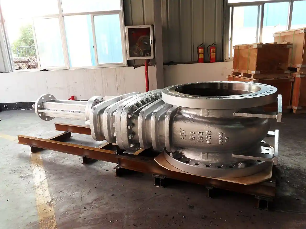
An expanding gate valve is a through conduit pipeline isolation valve whose closure assembly has two cooperating pieces, a gate and a segment, that slide together to mid stroke and then mechanically expand apart so that the segment wedges against the downstream seat face and the gate holds the upstream seat, producing a positive mechanical seal in both the fully open and the fully closed positions. Because the flow bore stays a continuous round passage in the open position, the valve passes cleaning and inspection pigs, and because the seal is made by mechanical expansion rather than by pressure pushing a slab against a seat, it seals reliably at low differential and in dirty, multi phase, and high pressure pipeline service. AMPO POYAM and Flowserve catalog through conduit double expanding gate valves of this class for oil and gas pipeline and wellhead duty, and this page treats the valve as the purchasing object.
This page is written for the engineer specifying expanding gate valves for pipeline block, wellhead and tree, tank farm, and process isolation where double block and bleed integrity or pigging capability is on the requirement list. It works through what the mechanism actually does and what is being bought, how the gate and segment expansion creates its seal, which body classes and standards apply, the parameters that appear on manufacturer data sheets, and the selection factors and RFQ language that decide whether the installed valve holds bubble tight isolation across a decade of service.
The decision concentrates in five places: the duty standard, API 6D pipeline versus API 6A wellhead, that fixes the design envelope, the bore and pressure class that set body and end connections, the seat and seal system, metal or soft, single or double piston effect, that matches the fluid and temperature, the operator choice across manual gear, hydraulic, and actuated, and the testing evidence behind the seat seal claims. Get those right and the trim, materials, and options follow.
Chapter 1 / 06
What an Expanding Gate Valve Is and What Is Being Decided
The machine this page describes is a full bore wedge expanding gate valve. Inside a forged or cast body with flanged or welded ends sits the closure assembly: a gate carrying a mating segment, both drilled to the full pipeline bore, guided in bonnet slides, and driven by a stem with a mechanism, most commonly a T slot and wedge roller arrangement, that first translates the assembly axially and then, near the ends of travel, converts further stem motion into radial expansion of the segment against its seat ring. Seats are floating metal or resilient seated rings in the body pockets. The valve is part of the same through conduit family as slab gate valves but seals by designed mechanical interference instead of relying on line pressure to seat a slab.
What is being decided when an expanding gate valve is purchased is a mechanical double block and bleed capability plus a piggable bore plus a cycle life. The buyer is purchasing bubble tight isolation against both seats with a body cavity that can be vented through a bleed to prove seat integrity, a bore that matches the pipeline inside diameter so pigs and tools pass, and a closure mechanism that keeps sealing through the grit, wax, and multi phase slugs that pipeline and wellhead service push through it, with warranty backed seat test results at low and high differential. Everything on the manufacturer data sheet, class, bore, seat type, torque or thrust figures, test certificates, exists to support those three guarantees.
The expanding gate valve sits in the gate valve family with defined neighbors and boundaries. It is not the plain wedge gate valve of utility service, whose solid wedge dips into the flow and seals one seat by wedging, leaving a cavity and a partial bore. It is not the knife gate valve of slurries and pneumatics, a thin blade for shut off in low pressure duty. And it is not the slab gate valve, the other through conduit geometry, whose floating slab is pushed against a seat by line pressure and which the live gate valve page already lists as part of the same geometry family: the expanding design deliberately adds mechanical expansion so that low differential and either flow direction seal as firmly as full line pressure. Buyers who only need a cheap open close device should buy a cheaper gate; buyers who need to prove isolation, pass pigs, or seal dirty service buy this one.
Different buyers buy the same valve for different reasons. A pipeline operator buys it as a block valve on either side of a pig launcher station, valving that must pass the pig launched by the pig launcher barrel and then isolate the section for maintenance. A production operator buys it as a wellhead wing or master valve where sand and multi phase flow destroy softer trims. A tank farm buys it for isolation under low differential where a pressure assisted slab would weep. A gas plant buys it for double block and bleed duty on meter runs and scraper traps where proving zero flow matters to custody and safety. The specification language differs, but the mechanism physics is shared.
The economics deserve their own paragraph because the expanding gate valve is a premium product and its cost is only justified against failure. Its purchase price runs well above a wedge gate of the same class, and against a slab gate it carries the premium of the expansion mechanism and harder seat engineering. Against that stand avoided costs: a pig stuck on a protruding seat is a pipeline excavation, a passing block valve is a shutdown or a vent and flare event, and a valve that will not seal at low differential delays commissioning and hot tap work. The honest comparison prices the consequence of the valve failing to seal, not just the valve, and in most pipeline contexts that arithmetic favors the expanding design at block valve stations.
A short tour of named duties makes the valve concrete. On a 48 inch gas transmission line, a station block valve pair closes and the cavity between them vents to prove isolation before a cut in. On a wellhead flowing wet gas with sand, a wing valve cycles under abrasion that would lap a soft seat away in months. On a crude terminal meter skid, double block and bleed valves isolate the meter while proving runs continue on the bypass. At a subsea template, an expanding gate valve in a forged body holds isolation for years between interventions. Each duty names the same knobs, class, bore, seat system, operator, and test evidence, with numbers that scale while the gate and segment geometry barely changes.
Chapter 2 / 06
How the Gate and Segment Do the Work
The mechanism is best followed through a closing stroke. At the open position the assembly is expanded: the segment is pressed against the downstream seat and the gate holds the upstream seat, so the valve seals in the open position too, an unusual and useful property that keeps seat faces wiped and the body cavity isolated from line grit while running. As the stem retracts, the first part of travel collapses the expansion and translates gate and segment together across the bore, wiping both seats. Near the closed position the mechanism converts remaining stem travel into radial expansion again, and the segment wedges against the downstream seat with a designed force independent of line pressure while the gate takes the upstream seat. Opening reverses the sequence, collapsing before travel and expanding at the end.
The seal force, not the line, is the design point. In a slab through conduit valve the floating slab relies on differential pressure to push it against a seat, so at zero or reversed differential the seal force can fall to spring levels. In the expanding design, the wedge roller or cam mechanism generates seat load from stem thrust, so the valve seals bubble tight at full line pressure, at low differential, and under either flow direction, and it keeps that seal under temperature cycling because the mechanism can be designed with the interference to accommodate thermal growth. That mechanical independence from pressure is the single sentence that justifies the valve's existence and its price.
Double block and bleed follows from the two independent seats and the body cavity. With the valve closed, the cavity between the upstream and downstream seats can be vented through a body bleed tap: if both seats hold, pressure in the cavity decays to zero and stays there, proving that neither seat leaks, which is the double block and bleed proof. With two such valves in series and a bleed between them, the arrangement becomes the classic double block and bleed station for maintenance isolation. Some expanding designs carry double piston effect seats in the API 6D sense, seat rings that self relieve or lock by piston action, and the specifying engineer should be precise about which API 6D seat category, single piston effect with self relieving, or double piston effect, the application needs, because the trapped cavity relief philosophy differs between them.
Materials and sealing surfaces do the work under the mechanism. Bodies are forged or cast low alloy or stainless steel for sour service to NACE MR0175 with hardfaced seat pockets; gate and segment faces are hardfaced or through hardened martensitic stainless, lapped to seat finish; resilient seat inserts, where the design uses them, are elastomer or polymer inserts captured in metal seats for resilient bubble tight shut off within their temperature envelope. Stem seals are graphite or elastomer packing with a backseat for injection, and many valves offer emergency seat and stem sealant injection ports as a field rescue for seal damage in service. The trim material stack must match the fluid: sand laden wellstream wants carbide or hardfaced trims, sour gas wants qualified materials, low temperature service wants impact tested bodies.
Operators and the mechanism share a duty curve. Because the expansion phase multiplies seat load from stem thrust, the valve demands a torque or thrust profile with peaks at the beginning and end of travel and a valley in the middle, a profile actuator sizing must respect at worst case differential and after years of service wear. Manual valves use bevel gears on larger sizes; pipeline stations use hydraulic or electrohydraulic actuators sized on the valve's stated thrust requirement; wellhead service uses hydraulic actuators with positioners. The data sheet thrust figures at maximum differential, with the sealant system dry, are the numbers an actuator supplier must size against, and understated thrust in the datasheet is an actuator sized to fail in service.
Cavity management closes the mechanism story. The body cavity between seats can trap line fluid, and in services where the trapped fluid can build pressure by thermal expansion or freeze by hydrate or wax formation, the valve needs cavity relief into the line, or an external relief route, plus injection ports for sealant or glycol. In sour or lethal service the cavity vent is a safety feature, routed to a safe location. The buyer should ask explicitly how the cavity relieves, what the trapped fluid volume is, and what the bleed and injection porting arrangement is, because these details differ between manufacturers and are frequently discovered only at commissioning.
Chapter 3 / 06
Body Types, Standards Classes, and Duty Boundaries
The valve is built in two standards worlds and the RFQ must name which one it is buying. API 6D is the pipeline valve specification, covering valves for the petroleum and natural gas pipeline transportation industries, with classes through API 6D pressure classes equivalent to ASME 150 through 2500, full bore and round bore requirements, seat testing categories, and the double piston effect and single piston effect seat taxonomy. API 6A is the wellhead and Christmas tree equipment specification, with its own pressure classes and material classes, PSL levels, and performance levels, and wellhead expanding gate valves are bought to it. A valve offered without a stated standard and edition is a valve that will be argued about at inspection.
Duty standard
Typical service
Classes
Key demand
API 6D pipeline
transmission block valves
ASME 150-2500
Full bore, DIB or DBB proof, pigging
API 6A wellhead
master, wing, tree valves
6A psi ratings
PSL and material class, sand trim
ISO 14313 equivalent
pipeline, international
as 6D
Same product under ISO flag
ASME B16.34 general
process isolation
150-2500
Wall class, softer duty
NACE MR0175 adder
sour service
any class
Material qualification
End connections and body construction follow the station design. Welded ends, raised face or ring joint flanges, and hub connections each carry pressure class and installation implications; forged bodies dominate high pressure wellhead sizes while cast bodies serve large pipeline bores where forging cost is prohibitive. Full bore means the bore matches the pipe inside diameter within 6D tolerance so gauging plates and pigs pass, and the data sheet should state minimum bore, not nominal. Bonnet designs are plain or extended for buried or cold service, and the stem extension on buried valves brings the operator above grade, a detail station layouts depend on.
Duty boundaries keep the selection honest. The expanding gate valve is an isolation valve, not a throttling valve: flow under a partially open gate slams the assembly and erodes seats, so modulating service belongs to globe valve trims, and check function belongs to a check valve downstream. It is not the cheap answer for utility water or air where a wedge gate or a butterfly does the job at a fraction of the price. It earns its place where pigs must pass, where isolation must be proven against both seats, where dirty or multi phase service would defeat a pressure assisted slab, and where the cost of a passing valve is measured in shutdowns. Within those boundaries it is the isolation workhorse of pipeline and wellhead engineering.
Where it sits in a station assembly matters as much as the valve itself. At a pig station the valve sits beside the pig launcher barrel and its isolation partner; at a meter run it pairs into double block and bleed with a bleed valve between; at a compressor or pump station it isolates suction and discharge with a bypass around; and on a tree it stacks with the master and swab valves. Spherical and bar stock check valves, ball valve isolation alternatives, and the three phase separator isolation valves of production packages all appear in the same station P and IDs, and standardizing operators and spare trim across the station is a real maintenance decision the buyer should make consciously rather than valve by valve.
Chapter 4 / 06
Key Specification Parameters
The data sheet parameters fall into four groups: envelope, sealing, mechanics, and evidence. Envelope parameters are nominal size, minimum bore, pressure class, end connections, face to face standard, and temperature rating at class. Sealing parameters are seat design, metal or resilient, single or double piston effect, cavity relief philosophy, and seat leakage class claimed. Mechanical parameters are stem thrust or torque to operate at maximum design differential, number of expected cycles, materials of body, trim, and seals, and the sealant injection provisions. Evidence parameters are the test certificates: shell and seat test per the standard's acceptance leak rates, fire test qualification where required, and material certificates. A quotation that omits the seat test acceptance basis is not comparable to one that states it.
Parameter
Typical range
Design note
Size range
2-60 inch
Forged bodies dominate small, cast large
Pressure class
150-2500 ASME
6A psi classes on wellhead duty
Bore
full, piped ID
Pig and gauge passage proof
Seat system
metal or resilient
SPE self relieve or DPE per 6D
Temperature
-46 to +200 C class
Impact tested bodies at low end
Cycles
isolation duty, low
Not a throttling valve
Actuation thrust
per data sheet
Actuator sizes on this number
Fire safe
API 607 or 6FA
Where the station requires it
Sour service
NACE MR0175
Material qualification scope
Seat test evidence deserves explicit specification because it is the valve's whole point. API 6D assigns valves to seat test categories by seat function: single piston effect seats with self relieving behavior and double piston effect seats that do not self relieve must each be proven against the stated acceptance, low pressure and high pressure seat tests in both directions for DIB configurations, with the bleed port used to demonstrate each seat independently. The buyer should demand the test procedure and acceptance leak rates in the data sheet, and for isolation critical service, a witnessed factory acceptance test that proves both seats hold at the stated differentials. Field retesting at the station, using the body bleed to check seat integrity against line pressure, should be in the maintenance plan from day one.
Materials traceability and special qualifications round out the sheet. For sour service the NACE MR0175 or ISO 15156 qualification covers hardness and heat treatment of body, trim, welds, and springs, and the certificate scope matters as much as the claim. Low temperature service needs impact tested body material at the minimum design metal temperature. Fire tested qualification to API 607 or API 6FA applies where station fire philosophy demands post fire sealing. Anti static devices, drain and bleed valve sizing, and position indication, from plain indicator to limit switch box, are line items that belong on the data sheet rather than in a verbal agreement.
Operator and interface parameters close the sheet. Manual bevel gear operators state handwheel rim force at worst case differential; hydraulic and electric actuators state required thrust and stroke time, and their power unit requirements, hydraulic pressure supply or motor voltage, land on the station electrical and hydraulic load list. Stroke time matters on pipeline safety sections where closure must beat a rupture wave, and slam tolerant actuators with mid travel cushioning protect the mechanism. The valve actuator package should be quoted as tested together, because a perfectly specified valve under an actuator that cannot deliver its thrust curve is a valve that will not close when the pipeline needs it to.
Chapter 5 / 06
Selection Decision Factors and RFQ Language
Selection starts from the duty sentence, not the valve catalog. The designer writes the service, fluid, and operating conditions; the isolation philosophy, double block and bleed station, pigging passage, wellhead sand service; the pressure class and bore that the pipeline or tree sets; the environmental envelope, buried or above grade, temperature extremes, sour gas; and the failure consequence that justifies the premium. From that sentence the standard choice, API 6D or 6A, the seat system, and the operator follow with little freedom. Writing these inputs into the RFQ is what makes bid tabulation an engineering exercise rather than a price exercise.
Duty driver
Favored configuration
Watch item
Pipeline block with pigging
6D full bore, DPE seats
Bore tolerance, actuator thrust
DBB meter isolation
paired valves plus bleed
Seat test acceptance per seat
Wellhead sand service
6A, hardfaced trim
NACE scope, cycle wear
Buried station valve
extended bonnet and stem
Cavity relief and injection reach
Fire sensitive area
fire tested qualification
Post fire seat performance
Seat system choice is the second decision and it divides by cavity philosophy. Single piston effect self relieving seats vent trapped cavity overpressure to the line automatically, protecting against thermal expansion lock, the right default for liquid and warm services. Double piston effect seats hold tighter in both directions and support DIB classification, but require deliberate cavity relief management since trapped pressure will not self vent, the right choice where isolation integrity outranks convenience. Resilient inserts buy bubble tight soft sealing within temperature limits; all metal seats serve hot and abrasive duty at a slightly softer leakage class. The wrong seat philosophy here shows up as either a weeping valve or a hydraulically locked cavity at the worst possible moment.
Operator selection is the third decision and it is made with the valve, not after it. Manual gear operation fits infrequent isolation in accessible stations; hydraulic actuators, powered from station skids or gas driven hydraulic pumps on remote gas lines, fit pipeline block valve duty including closure on line break signal; electric actuators fit powered stations with battery or capacitor backup for last stroke closure. Stroke time requirements from the station safety study, closure within seconds on rupture detection, drive the actuator size and the power unit, and slam damping protects the expansion mechanism at the end of travel. The interface between valve thrust curve and actuator capability is the single most common source of field failure in this product class and deserves a witnessed shop test of the package.
The RFQ language that returns comparable offers states the duty sentence and the evidence demanded. State standard and edition, size, minimum bore, class, end connections, seat system with SPE or DPE designation, cavity relief philosophy, materials with NACE scope where applicable, fire test requirement, operator type with power supply and stroke time, sealant injection provisions, factory seat test acceptance rates with witness requirements, and spare parts initial fill. A complete RFQ paragraph reads: API 6D expanding gate valve, 24 inch full bore 1.090 inch wall pipe ID minimum, class 600 weld end, DPE seats with DIB 1 classification, sour service to NACE MR0175, fire safe to API 6FA, hydraulic actuator closing within 30 seconds against full differential, factory seat test witnessed to 6D acceptance.
Commercial comparison is only fair on a normalized basis. Offers should be forced onto one table: standard and edition actually offered, bore minimum guaranteed, seat system and test acceptance per seat, thrust at maximum differential and actuator margin, materials and certificate scope, fire test status, delivery and the witness test provisions, and the spares package with seat rings, sealant, and packing. The cheapest offer is very often the one with the thinnest test evidence or an actuator sized to clean valve torque, and its life cycle cost lands higher the first time the station needs proof tight isolation. Where pipeline safety studies price risk, the seat test certificate column is worth more than the price column.
Chapter 6 / 06
Installation, Standards, Failure Modes, and Maintenance
Installation follows station practice with a few mechanism specific cautions. Weld end valves are welded into the line with the valve open and the seats protected from weld heat per manufacturer procedure, often with the closure assembly removed on large sizes; flanged valves torque to the gasket pattern without bowing the body; buried valves get extended bonnets to grade with cathodic protection continuity and a dry valve box or vault. The operator mounts on the valve centerline and its power lines land without straining; position switches are set on the installed valve, not on the bench. Before hydrotest, verify the seat side being tested and the cavity relief path, because testing the wrong side of a DPE seat against its locked cavity has bent more than one bonnet.
Failure modes have a known hierarchy. Seat face damage from debris or from throttling in service is first: a nicked seat face weeps and no sealant injection holds it indefinitely. Galling of the gate and segment expansion surfaces from dry cycling or dirt follows, raising operating thrust until the actuator stalls. Stem packing leaks develop with cycle count and temperature cycling, addressable by adjustment and sealant injection until repacking. Cavity problems, trapped hydrates, wax, or thermally locked pressure, block full travel and must be managed by the relief and injection provisions designed in. And corrosion under insulation or in buried service attacks bodies and bonnet joints on the inspection cycle. Nearly all of these announce themselves in rising operating thrust and seat test trends before they announce themselves as leaks.
Symptom
Likely cause
First response
Seat test fails downstream
seat face damage
Sealant injection, plan seat refurbish
Operating thrust rising
expansion surface wear
Lubricate per OEM, actuator margin check
Packing weep
packing wear
Adjust, inject, schedule repack
Valve stalls mid travel
cavity obstruction
Bleed cavity, injection, review service
Bore damage found by pig
throttled flow erosion
Prohibit throttling, refurbish bore
Maintenance is planned around isolation proof rather than hours run. Periodic part stroke exercise, moving the closure off seat and back within station rules, keeps the mechanism free without breaking isolation philosophy; annual seat integrity checks through the body bleed against line pressure prove both seats and log the trend; sealant injection follows the manufacturer interval in dirty service rather than waiting for a leak; and overhaul at rising thrust or failing seat tests renews seats, expansion surfaces, and packing in a shop with the lapping equipment the design requires. Spares strategy holds seat rings, a spare closure assembly on critical stations, packing, and sealant, because the lead time on a large bore closure assembly is measured in months.
Operational stewardship is what the purchase actually bought. Log every operation with differential and thrust readings, keep the throttling prohibition enforced in procedures because one throttling event can buy a season of seat damage, protect the cavity relief path from paint and insulation, and retest seats after any pipeline upset that slammed the valve. Stations that exercise, test, and trend their expanding gate valves get decades of bubble tight isolation from them, and stations that ignore them until the annual pig run sticks discover that the cheap column on the original bid tab was the expensive one in the end.
FAQ
What makes an expanding gate valve different from a slab gate valve?
Both are through conduit designs with a full pipeline bore, but a slab gate seals when line pressure pushes the floating slab against a seat, while the expanding design uses a gate and segment mechanism that mechanically wedges against both seats at the ends of travel. The expanding valve therefore seals bubble tight at low or zero differential and in either flow direction, independent of line pressure, where a slab can weep when pressure assistance disappears. Slab and through conduit geometries belong to the same valve family; the expansion mechanism is what this page's product adds.
What does double block and bleed mean for this valve?
With the valve closed, the body cavity between the two independent seats can be vented through the bleed tap. If both seats hold, cavity pressure stays at zero, proving isolation from both the upstream and downstream sides: that is double block and bleed from a single valve. Two such valves in series with a bleed between them form the classic DBB station. API 6D formalizes seat behavior as single piston effect or double piston effect, and the DIB classification depends on which the valve carries, so the RFQ should name the category.
Can pigs pass through an expanding gate valve?
Yes, that is one of its design purposes. In the open position the gate and segment retract to leave a continuous round bore matching the pipe inside diameter within API 6D tolerance, so cleaning pigs, gauging plates, and inspection tools pass without snagging. The bore minimum should be guaranteed on the data sheet, and pig station valves are function tested with a gauging plate before commissioning.
Should I choose API 6D or API 6A for my expanding gate valve?
Choose by the duty the standard governs. API 6D covers pipeline transportation valves, block valves on transmission lines, pig stations, and meter runs, with ASME pressure classes and its seat testing taxonomy. API 6A covers wellhead and Christmas tree equipment, master and wing valves, with its own pressure classes, material classes, PSL levels, and performance requirements. A few products are dual qualified, but the RFQ should name one governing standard and edition, because test acceptance and material scope differ.
Do expanding gate valves throttle flow?
No. They are isolation valves. Partially opening the gate exposes the closure assembly and seat faces to high velocity flow, which erodes the bore and destroys seat sealing; the mechanism is also not designed to hold position under flow forces. Throttling duty belongs to globe valve trims or control valves, with the expanding gate valve either fully open or fully closed and check function handled by a separate check valve.
How is the valve tested to prove it seals at low pressure?
Factory seat testing per API 6D applies both high pressure and low pressure seat tests, in both flow directions for double isolation configurations, using the body cavity bleed port to load and prove each seat independently. Because the expansion mechanism generates seat load from stem thrust rather than line pressure, the valve passes the low pressure seat test that pressure assisted designs find hardest. Field retesting uses the same bleed port logic against line pressure and belongs in the maintenance routine.
What maintenance does an expanding gate valve need?
Periodic part stroke exercise keeps the mechanism free, sealant injection at manufacturer intervals protects seats in dirty service, stem packing is adjusted or injected as it weeps, and annual seat integrity checks through the body bleed prove both seats and build the trend that predicts overhaul. Refurbishment renews seat faces, expansion surfaces, and packing in a qualified shop. The two operational rules that protect the investment are no throttling and no ignored thrust trend: both seat damage and mechanism wear announce themselves early in those two numbers.