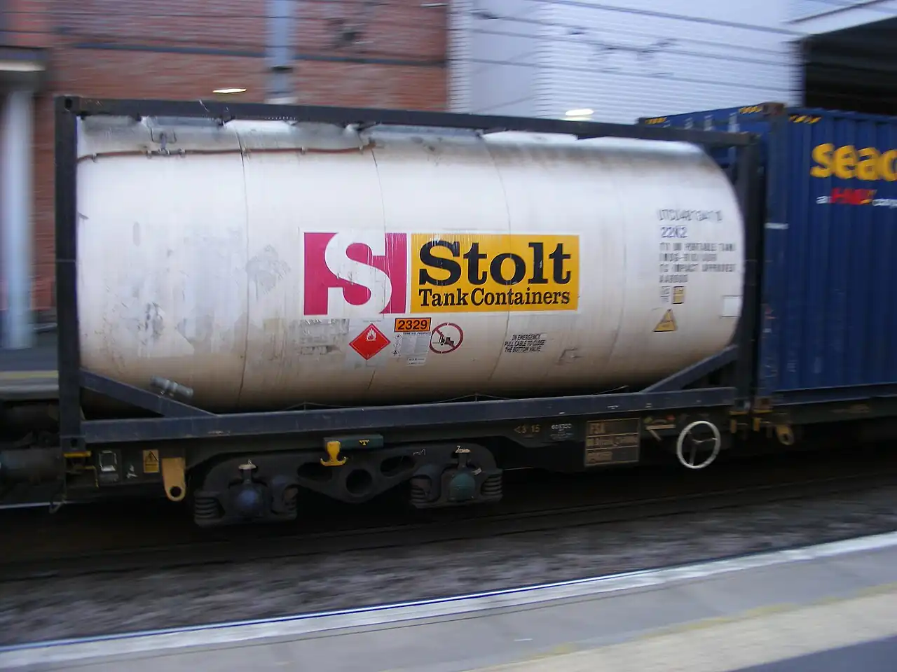
A slug catcher is the inlet facility at the end of a multiphase or wet gas pipeline that receives the intermittent liquid slugs the line delivers and holds them, so that the gas plant, compressor, or treating equipment downstream sees a steady, designable flow instead of a surge it was never sized for. It is built either as one large vessel or, on the biggest duties, as an array of long parallel pipes, the finger or harp type, that together hold the design slug volume and separate the gas as the liquid drains. Taylor Forge, Spitzer, WeldFit, and Transtech Fabrication are among the fabricators that build these units, and this page treats the slug catcher and its immediate controls as the purchasing object.
This page is written for the engineer specifying the inlet end of a wet gas or multiphase pipeline system. It works through how slugs form and how big they get, how vessel and finger geometries catch and buffer them, the parameters that appear on vendor data sheets, and the selection factors and RFQ language that decide whether the installed unit protects the downstream plant through its worst pigging run.
The decision concentrates in five places: the design slug volume and how often it arrives, the gas and liquid rates between slugs, the plot space the site offers, the pressure class and materials the pipeline dictates, and the liquid handling that drains the unit fast enough for the next slug. Get those right and the vessel or finger count follows.
Chapter 1 / 06
What a Slug Catcher Is and What Is Being Decided
The industrial machine this page describes is a pressure vessel or a header array installed at the receiving end of a pipeline, upstream of the plant's normal separation train. In vessel form it is a large two or three phase drum, horizontal most often, rated at or above the pipeline's design pressure, with a gas outlet that runs steady to the downstream separators or compressors and a liquid outlet that runs to storage or treating under level control. In finger form it is a set of long, slightly sloped large bore pipes manifolded in parallel, each pipe a settling and storage volume, with gas leaving the tops of the headers and liquid collecting and draining from the low ends; units of several fingers, each hundreds of meters long, are built wherever the slug volumes and the plot allow.
What is being decided when a slug catcher is purchased is a protection guarantee: the unit must swallow the design slug, the largest liquid volume the pipeline can deliver, including the full liquid inventory a pig run pushes ahead of it, without passing a surge downstream and without tripping on high level, and then drain that liquid away fast enough to be ready for the next one. Everything on the vendor data sheet, volume, working pressure, gas capacity, liquid drain rate, nozzle sizes, exists to support that guarantee, and the five decisions this page works through determine whether it holds on the worst operating day the pipeline produces.
The slug catcher occupies a specific place at the plant fence and its boundaries matter. It is not a three phase separator: the separator splits a steady flowing stream into gas, oil, and water as a continuous process duty with retention time and interface control as its design core, while the slug catcher exists precisely because the arriving stream is not steady. It is not a knockout drum: the KO drum removes entrained liquids and condensate from a gas stream, and the three phase separator page and the knockout drum page both name the slug catcher as their pipeline end neighbor without doubling it. And it is not a pig launcher: the launcher and receiver are the pipeline's cleaning and inspection hardware, whose runs create the biggest slugs the catcher must catch; they are equipment cousins, not competitors, at opposite ends of the same line.
Different buyers buy the same unit for different reasons. A gas plant at the end of a wet gas gathering system buys it so its compressors and amine or glycol treating never see liquid. A pipeline company buys it at a terminal so metering and downstream custody transfer stay single phase. An offshore platform buys a compact vessel form because deck space is priced by the square meter. An onshore shale or coal seam gas operator buys finger arrays because the slug volumes are huge and the plot is dirt cheap. The specification language differs, but the surge physics is shared.
A short tour of named duties makes the unit concrete. At a gas plant receiving a 90 kilometer wet gas line, terrain slugs arrive in the rainy season when rates swing, and the slug catcher drains to condensate storage under level control while gas runs steady to the compressors. At a terminal, a pig run launches upstream and arrives as a defined liquid front, several hundred cubic meters pushed ahead of the pig, and the catcher holds it while the pig receiver opens downstream of it. At an offshore platform, a compact three phase slug catcher does double duty, catching slugs and making a rough gas oil water split that the downstream separators polish. In each duty the same five knobs appear: slug volume, rates, space, pressure class, and drain.
The purchase is never the vessel alone, and the RFQ that forgets the liquid side buys a buffer that cannot empty. The drain system, pumps or pressure driven flow to storage, the level instrumentation that gates it, and the gas outlet sizing that keeps the downstream plant fed during the catch, are one system with the vessel. On finger units the piping manifold, the slope and supports of the headers, and the collection pot at the low end are the product as much as the pipe itself, and the plot arrangement that fits hundreds of meters of sloped header into the site is an engineering decision that precedes the purchase order.
Chapter 2 / 06
How Slugs Form and How the Catcher Buffers Them
Slugs are the pipeline's normal misbehavior, and they arrive in three families. Terrain slugs form in hilly lines where liquid accumulates in the valleys until gas pressure behind it lifts the whole accumulation out as a slug; they recur continuously at low gas velocities and arrive at the receiver as a periodic surge. Rate change slugs form when the line ramps up or down: raising gas velocity sweeps accumulated liquid forward, and the swept inventory arrives as a front. Pigging slugs are the deliberate family: a pig launched into the line pushes essentially the entire liquid holdup ahead of it, arriving as the single largest, most predictable slug the catcher will ever see, which is why pig run inventories anchor so many sizing exercises.
Slug volume is the sizing number, and it is a simulation output before it is a vessel parameter. Multiphase flow simulation of the actual line profile, with the actual fluid, rates, and temperature profile, predicts liquid holdup and slug arrival volumes for each operating case; the pigging case is calculated directly as the liquid inventory in the line at pig launch. Design practice sizes the catcher for the governing case, often the full line inventory on a pig run, plus a margin, and cross checks against the terrain and ramp cases at the rates the line will actually run. A catcher sized on average flows instead of these cases is a vessel that protects the plant on the days nothing happens.
The buffering itself is volume plus drain rate working against the slug's arrival. As the slug enters, the vessel or fingers absorb the liquid while the gas outlet continues running at close to line rate, the gas space and the liquid level rising together within the design band; the level instrumentation and control valve on the liquid outlet then drain the stored liquid to downstream handling at the rate the drain system allows. Hold time is the quiet third number: how long the unit can hold the design slug while its normal liquid production keeps arriving, before the high level trip that shuts the pipeline in. Plants that cannot afford shut-ins buy hold time, not just capacity.
Gas capacity is the matching constraint on the other side of the unit. Between slugs, and during them, the gas flowing through the catcher must leave without carrying liquid over to the compressors and treating downstream, which sets a gas velocity and disengaging length requirement in the vessel or along the fingers, often with a mist eliminator at the gas outlet to catch what gravity does not. The unit is therefore sized in two directions at once: liquid volume for the slug, and gas cross section and length for the steady and transient vapor rates, and the larger of the two requirements in each dimension sets the steel.
Liquid handling downstream closes the loop. The drained liquids run to storage, to a produced water system, or back into the separation train, moved by pumps where the pressure is gone and by pressure differential where it is not; a level transmitter on the catcher drives the drain control valve, and independent high level switches gate the pipeline or divert the inlet when the drain cannot keep up. On three phase duty a rough interface control and water draw add an oil water split to the same drum, with the downstream oil water separator and heater treater polishing what the catcher starts. The vapor recovery unit on the liquid storage catches the flash gas the drain releases, and a gas detector watches the enclosure where the liquids collect.
Slug arrival behavior is increasingly a measured quantity rather than only a simulated one. Fiber optic distributed sensing along the line, gamma densitometers, and the pressure signature at the receiver all give operations a running picture of holdup building and fronts moving, and plants that connect those signals to their drain and level strategy start the recovery before the slug arrives instead of after. For a buyer the relevance is simpler: the instrumentation that watches the inlet, pressure, differential, and a fast level trend on the catcher itself, is what turns the design volume from a static number into an operating margin, and it belongs on the data sheet alongside the steel.
Pigging deserves its own paragraph because it is the worst case and the cooperation case at once. The pig receiver sits at the same fence as the slug catcher, and a run is coordinated: the plant prepares downstream capacity, the drain system is verified, and the launcher sends the pig. The arrival is not a surprise but a managed event, with the catcher absorbing the front while the operator watches the level trend and the downstream units ride through on the buffered gas. A well specified catcher turns the pig run from a plant upset into a Tuesday, and that, as much as any liquid number, is the product.
Chapter 3 / 06
Vessel and Finger Types and Duty Boundaries
The vessel type slug catcher is a single drum, horizontal in most cases to maximize the gas liquid disengaging length and the liquid storage per unit of steel. It suits moderate slug volumes, offshore and plot constrained sites, and duties where a three phase rough split in the same drum is wanted; its limits are fabrication and transport, because a single vessel beyond roughly 300 to 400 cubic meters becomes a heavy lift and transport project of its own. Two vessels in parallel or in series appear where the volume demands and the plot allows.
The finger or harp type is the volume machine: rows of large bore pipe, typically 0.9 to 1.5 meters in diameter, sloped at one to three degrees to the drain end, manifolded so the slug distributes across them, and laid out in harp shaped bundles on a plot that would never fit an equivalent vessel. Fingers win where slug volumes run into the thousands of cubic meters, onshore terminals and trunk line receivers, and where the ground is cheaper than the fabrication shop. Their costs are plot, piping manifold complexity, and the instrumentation spread along the headers, and their liquid drain behaves as a distributed system rather than a single pot.
Type
Slug volume range
Footprint
Where it wins
Single horizontal vessel
tens to about 400 m3
compact
Offshore, plot constrained, moderate slugs
Parallel vessels
hundreds of m3
moderate
Volumes beyond one vessel, maintenance isolation
Finger or harp array
1,000 to beyond 10,000 m3
large, onshore
Trunk lines, terminals, big pigging inventories
Three phase slug catcher
vessel range
compact
Rough gas oil water split plus surge duty in one drum
Materials follow the pipeline's fluids and the sour service question. Carbon steel is the default for sweet dry service; wet sour gas with hydrogen sulfide above the threshold pushes the steel into sour service classes with hardness control, qualification testing, and the matching manufacture and inspection regime the project's materials engineer specifies. Corrosion allowances, internal coatings, and injection points for corrosion inhibitor arrive with the fluids, and chloride and CO2 content move the needle on vessel metallurgy and on the drain system's valves and pumps. Cold service at high pressure and low ambient adds its own material and fracture toughness line to the data sheet.
Duty boundaries against the neighbors deserve plain language. When the arriving stream is steady and the job is splitting it into phases, the machine is a three phase separator, and this unit's job is upstream of that, making the stream steady. When the job is removing trace liquids from a gas flow, the machine is a knockout drum with its mist eliminator, a smaller duty that follows the slug catcher rather than replacing it. When the job is launching and receiving pigs, the machines are the launcher and receiver, whose hardware this unit supports by catching what the runs push. The flash tank handles its own blowdown and flash duty elsewhere in the plant, and the coalescing filter polishes compressor feed after the separation train. Each neighbor has its page; this one is the buffer at the fence.
Chapter 4 / 06
Key Specification Parameters
Vendor quotations for slug catchers revolve around a compact parameter set, and a buyer who reads them against the pipeline's simulation cases can compare offers on engineering terms. The table below collects the parameters that decide performance for mainstream midstream duty, with the ranges a reviewing engineer should expect across vessel and finger forms.
Parameter
Typical specification range
What it decides
Design slug volume
tens to beyond 10,000 m3
The governing case the unit must swallow
Design pressure
pipeline class, ANSI 150 to 900
Wall thickness, class of nozzles and valves
Design temperature
site low to line high
Materials and fracture toughness basis
Working liquid volume
slug volume plus margin
Hold capacity between drain and trip
Gas capacity
line rate steady and transient
Vessel diameter or finger count and length
Hold time at design slug
minutes to hours
Grace before a high level shut in
Liquid drain rate
matched to downstream handling
Recovery time to ready for next slug
Finger geometry
0.9 to 1.5 m bore, 1 to 3 degrees slope
Array volume and drain behavior
Level instrumentation
transmitter plus independent switches
Drain control and pipeline protection trips
Materials class
carbon steel to sour service grades
Corrosion life and compliance regime
Two of those numbers do the sizing work. Design slug volume, from the pipeline simulation and the pigging inventory, fixes the liquid volume the unit must hold, and every other dimension serves it. Gas capacity fixes the cross section, vessel diameter or finger count, needed to pass the line's vapor rates without liquid carryover, and on many units the gas requirement, not the volume, sets the steel weight. The honest specification quotes both with their cases, because a catcher quoted on volume alone has an unknown gas story.
The remainder of the parameter set carries the protection function. Hold time states how long the unit rides the worst slug before shutting the line in, a number the operations team lives with; drain rate states how fast it recovers, and must be checked against the downstream liquid system, pumps, storage, and water handling, not just the outlet nozzle; and the level instrumentation arrangement, continuous transmitter for control and independent switches for trips, is the safety layer that turns a buffer into a protected one. On finger units, slope, manifold symmetry, and the low end collection pot are the geometry details that decide whether the array drains as designed.
Chapter 5 / 06
Selection Decision Factors and RFQ Language
Pipeline definition comes first because the unit is a mirror of the line. The specification should state the line's profile and length, the fluid composition including water, condensate, and hydrogen sulfide and carbon dioxide content, the operating pressure and temperature envelope, the gas and liquid rates across the operating year, and the simulation cases for terrain, ramp, and pigging slugs with their volumes and frequencies. The pigging plan, how often, which pigs, and with what line inventory at launch, anchors the worst case, and the plant's tolerance for shut-ins anchors the hold time.
Site and downstream context come second. Plot space and its price decide vessel against fingers before any vendor is consulted: a compact site buys a vessel or two, a sprawling onshore site buys the harp. The downstream gas plant states what steady flow it needs and what liquid carryover it tolerates, which sets the gas side sizing and the mist elimination; the downstream liquid system states what drain rate it accepts, which sets the recovery time. Sour service, ambient lows, and any offshore modular constraints move the materials and the fabrication plan.
Selection factor
What to specify
Common mistake
Pipeline cases
terrain, ramp, pigging volumes and rates
Sizing on average flows with no slug cases
Hold time
minutes or hours of grace required
Capacity without the shut in tolerance stated
Plot and form
space available, vessel or finger preference
Finger layout forced into a vessel sized plot
Gas side duty
rates, carryover tolerance, mist elimination
Volume sized unit with undersized gas cross section
Drain system
rate, pumps or pressure drive, downstream limits
Nozzle sized drain into an undersized liquid system
RFQ language that produces comparable offers follows from those factors and should read like a pipeline data sheet. State the simulation cases and their volumes, the pressure class and temperature envelope, the gas and liquid rates, the hold time requirement, the plot available, and the downstream tolerances on carryover and drain. Ask every fabricator to state the volume actually held between normal and trip levels rather than the total vessel volume, the gas capacity basis, nozzle sizes and orientations, the level instrumentation arrangement, the materials and sour service compliance map, and the references on comparable lines and slug volumes.
Guarantees and acceptance close the procurement. A defensible offer guarantees the working volume between stated levels, the gas capacity without carryover at stated rates, and the drain performance, demonstrated at commissioning with a water or produced fluid fill and drain test, and witnessed on the first pig run where the line's schedule allows. Hold every bidder to the same cases, weight offers on protected plant availability rather than vessel price, and include the instrumentation and trip testing in the acceptance scope, because the unit's whole value is demonstrated on the day the big slug arrives.
The balance of plant the RFQ must not forget: the inlet manifold and its distribution to vessel or fingers, the drain piping and pumps with their level driven control valve, the gas outlet with its mist eliminator and the downstream tie in, pressure relief with a safety relief valve and, where storage follows, a pressure vacuum relief valve on the tankage the liquids run to, and the instrument air and electrical scope that powers the measurement. A flash tank or vapor recovery unit connection catches the gas the drain releases, and the loading arm at the terminal downstream moves the liquids onward when they leave by truck or ship.
Chapter 6 / 06
Installation, Standards, Failure Modes, and Maintenance
Installation is a pressure vessel and, on finger units, a piping project. The vessel arrives as a heavy lift onto its saddles with the nozzles oriented to the plot; the finger array arrives as pipe strings to be set on supports at the design slope, manifolded, and hydrostatically tested as a system. Hookup connects the inlet from the receiver side, the gas outlet to the plant, the drain to the liquid system, and the relief paths to flare. Commissioning fills, calibrates the level transmitter and switches, and proves the drain rate with a timed fill and drain test before the first pig is ever launched.
Standards shape the unit through the pressure equipment regime. Vessel and piping codes govern the design, fabrication, and testing of the steel; the sour service regime, where the fluids demand it, governs material qualification and hardness control; pipeline codes govern the interface and the pigging hardware at the fence; and overpressure protection standards govern the relief sizing on the gas side. A buyer specifies outcomes, code stamps, sour class, relief basis, and lets the fabricator map them to the code edition its shop works to; what the buyer must not do is leave the level trip philosophy to the vendor's default, because that is the plant's protection decision.
Failure mode
Signature
Response
Liquid carryover to gas outlet
downstream compressor or treating upsets
Gas capacity recheck, mist eliminator service, level tuning
High level trip on drain shortfall
pipeline shut in during pig runs
Drain system bottleneck audit, hold time review
Finger manifold maldistribution
early high level on one header
Manifold symmetry and slope verification, drain balance
Sensing line flushing, redundancy, switch proof testing
Routine operation is event led. Between slugs the unit sits nearly empty with the drain throttled; during arrivals the operator watches the level trend against the predicted case and the drain system's response, and after each pig run the event is reviewed against the simulation that sized the unit, feeding the model back its field data. Maintenance is dominated by inspection and the instruments: thickness surveys on the vessel and headers, the level transmitter and switches proved on schedule, the drain valves and pumps serviced, and the mist eliminator inspected at turnarounds. On sour units, the inspection and inhibitor program is the unit's life story, and the records it produces are the asset's real documentation.
Operating readiness is the last piece of the product. The team that will run the unit trains on its cases, what a terrain slug arrival looks like on the trend, how a pig run's front differs, which drain lineup serves which liquid, and the trip philosophy is written into the operating procedures with the same care it was written into the specification. Spares follow the failure modes: level instrument sensing hardware, drain valve trim and actuators, seal and pump kits on pumped drains, and the gasket and bolting stock for the manifold flanges that finger units multiply. A buffer is only as good as the crew that is awake when it fills.
The end state of a well specified slug catcher is a plant that no longer knows what the pipeline is doing. Slugs arrive and disappear into working volume, the gas rate downstream never flickers, the pig runs are calendar items instead of emergencies, and the drain quietly refills the buffer for the next event. The neighbors mark the boundaries: separators split what this unit has calmed, the KO drum polishes the gas it releases, and the launcher and receiver create the worst case it was born to catch.
FAQ
What is a slug catcher for?
It is the buffer at the receiving end of a multiphase or wet gas pipeline. The line delivers intermittent liquid slugs, from terrain, from rate changes, and from pig runs, that would flood and trip the downstream plant. The slug catcher holds the design slug volume and drains it away at a controlled rate, so the gas plant, compressors, and treating see steady flow they can be designed for.
How is the required slug volume determined?
From multiphase simulation of the actual line: terrain slugging cases at operating rates, ramp up and ramp down sweep cases, and the pigging case, which is essentially the full liquid inventory in the line pushed ahead of the pig. The largest credible case, with margin, sets the design volume. A catcher sized on average flows protects the plant only on average days.
Vessel or finger type: which should I choose?
Vessels suit moderate volumes, tens to a few hundred cubic meters, compact plots, and offshore sites where every square meter is priced. Finger or harp arrays suit the big volumes, thousands of cubic meters of pigging inventory on trunk lines, where onshore plot is cheap and fabrication of an equivalent vessel is not. The plot and the volume decide together, before any vendor is asked.
How does a finger slug catcher work?
It is a set of long, slightly sloped large bore pipes manifolded in parallel. The arriving slug distributes across the fingers, gas disengarges along their length and leaves the tops of the headers, and liquid runs down the slope to a collection pot at the low end, from which the drain system empties it. Each finger is both a settling length and a storage volume, and the array holds far more liquid per unit of fabrication than any vessel.
Is a slug catcher the same as a separator?
No, the duties are adjacent but different. The slug catcher exists because the arriving flow is unsteady, and its design core is surge volume and drain rate. The separator splits a steady stream into gas and liquids, or gas, oil, and water, with retention time and interface control as its design core. On many plants the slug catcher calms the flow and the separators do the splitting; compact units sometimes combine both in one drum.
What happens if the slug catcher fills completely?
Protection layers act before that becomes carryover. The drain runs at maximum under level control, independent high level switches alarm and then trip or divert the inlet, and the pipeline is shut in or rerouted rather than letting liquid reach compressors and treating. Hold time, the minutes or hours between the design slug's arrival and that trip, is a specified number the operations team depends on during pig runs.
What materials does a sour service slug catcher need?
Sour service steel with hardness control and qualification to the sour regime the fluids define, when hydrogen sulfide content exceeds the applicable threshold, plus the corrosion allowance, inhibitor injection provisions, and inspection program that wet sour steel lives with. Carbon steel serves sweet dry service with a standard allowance. The fluids analysis, H2S, CO2, water, and chlorides, not the vendor's preference, sets the class.