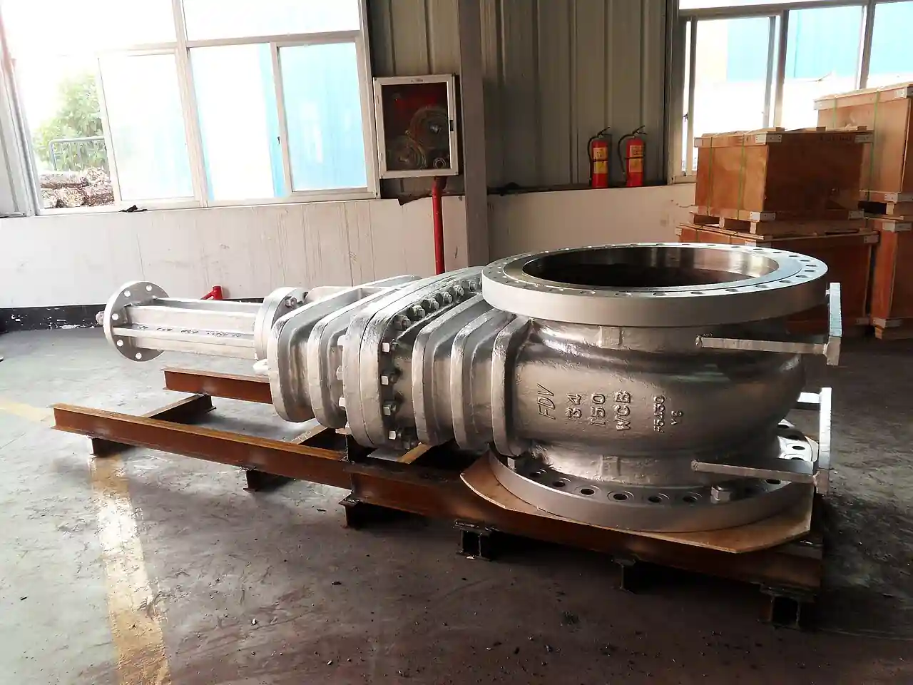
A pig launcher is the pressure vessel assembly that inserts a pipeline pig, a cleaning, batching, or inspection tool, into a pressurized line without stopping flow, and its paired twin, the pig receiver, gets the tool back out at the far end. The machine is an oversize barrel section with a quick-actuating closure at the outboard end, a reducer down to pipe bore at the inboard end, and a small valve train around it: a kicker line that pushes the pig out of the barrel into the stream, isolation valves on the run, vents and drains for depressurization and dewatering, and a pig signaler that confirms departure and arrival. Built as ASME Section VIII vessels on B31.4, B31.8, or B31.3 piping systems, traps serve pipelines from DN 50 gathering lines to 56-inch trunk lines at pressures to 100 bar and beyond.
Procurement engineers meet this equipment wherever pipelines are cleaned, batched, or inspected: crude and products lines on pigging programs for wax and water sweep, gas transmission lines mandating intelligent pig runs on regulatory intervals, water and effluent lines, and loading terminals batching grades. The decision this page settles is narrow and practical: how the barrel and reducer are sized for the pigs the line will actually run, which closure architecture and interlocks make the trap safe to open, how the kicker, bypass, vent, and drain valves are arranged so a launch is a procedure rather than an improvisation, and what the code, material, and sour service lines of an RFQ must say so the station passes both the hydrotest and the auditor.
This page treats the pig launcher, with its receiver twin treated inside the same station logic, as a purchasing object: barrel and reducer sizing against real pig dimensions, closure types and the interlocks that keep them honest, kicker and bypass hydraulics, pig signalers and station instrumentation, design codes and sour service materials, and the RFQ line set that turns a trap order into a station that operates as drawn. It is written for engineers who sign pipeline mechanical work orders, not for readers who want a brochure summary.
Chapter 1 / 06
What a Pig Launcher Is and What Is Being Decided
The pig is the tool and the trap is its airlock. A pipeline pig, from a foam swab to a multi-cup cleaning pig to an in-line inspection instrument carrying sensors and batteries, cannot pass through a valve or be inserted into a live spool; it needs a section of pipe larger than the line bore to be loaded into, a door that opens to atmosphere while the line stays pressurized, and a path for line pressure to push the pig from the barrel into the stream. The launcher is that airlock on the upstream end of the duty, and the receiver, with a longer barrel to catch and hold the arriving pig, is its mirror at the far end. Together with the connecting valves and instrumentation they form a pigging station, and the two vessels are almost always purchased as a designed pair even when the line item says launcher.
What is being decided in this purchase is a pressure vessel with an operating procedure attached. The barrel and closure are designed to code, hydrotested, and registered like any vessel; but the trap lives or dies by its valve train and interlock logic, because the sequence that makes it safe, isolate the run, equalize or depressurize the barrel, vent and drain, confirm zero energy, open the closure, load the pig, close and secure, pressurize from the kicker, launch on signal, is a procedure executed with valves, and every valve in that sequence is part of the purchase. A trap quoted as a barrel with two weld ends is half a machine; the RFQ in chapter 5 therefore buys the station, not the shell.
The safety weight of the decision is unusual for a piping component, and it deserves a plain sentence: the single most dangerous object in a pigging station is an opened closure on a barrel that is not fully depressurized, and quick-actuating closures have caused fatal accidents exactly that way. The industry's answer is engineering plus procedure: closures with built-in pressure warning indicators and safety devices that prevent opening under pressure, isolation and bleed arrangements with verifiable zero-energy states, interlocks where the operation warrants them, and written procedures that treat the closure like the energized equipment it is. Specifications that skip this layer to save a line item are not economical; they are the incident report written in advance.
The neighbors define the equipment's scope. The trap is not a valve: full-bore ball valves and gate valves serve its isolation train, and their own leaves carry that depth, but the trap's job is geometry, a place where the pig can exist outside the flow, which no valve provides. It is not a blind or isolation double-block-and-bleed assembly: spectacle blinds and blind flanges isolate lines for maintenance, and they appear adjacent to traps for station isolation, but they cannot pass or hold a pig. It is not a strainer: a y strainer protects equipment from debris; a pig removes debris from the whole line over kilometers. And it is not the pig itself or the pigging service contract, though both are priced around the station's capability, most importantly whether the trap can pass the longest and largest tool, usually an intelligent in-line inspection pig, that the line's integrity program will demand.
Scale runs from forgings to field-fabricated skids. Small traps, DN 50 to DN 150 lines, are often single-piece fabrications with a hinged or threaded closure, mounted at glycol and gathering systems. Mid-range traps, DN 200 to DN 600, are shop-fabricated skids with barrel, reducer, valve train, davits for closure handling, and pipe supports, trucked complete to site. Large trunk-line traps, DN 750 to DN 1400, are field-erected assemblies with crane-served closures, structural steel, and full station instrumentation, and on gas transmission systems they are regulated assets with documented inspection programs. The purchase pattern follows: small traps as catalog products chosen by size and class, large traps as engineered packages with design review, and the middle belonging to whichever the project's engineering hours decide.
Chapter 2 / 06
How the Trap Geometry Does the Work
The barrel is oversize on purpose. A pig's cups and brushes seal against the line bore, so the barrel must be larger than the pipe inside diameter, commonly the next standard size up, DN bore plus one or two nominal sizes, to let the pig slide in unloaded and free of the stream until launch. Barrel length follows the pig train: a single cleaning pig needs roughly 1.5 to 2 pig lengths plus closure clearance; a batching train or an intelligent tool with its cups, body, and batteries may need several meters; and receivers run longer than launchers, typically 1.5 to 2 times, because an arriving pig carries momentum and the barrel must decelerate and hold it, sometimes with a bump stop or receiving basket, without slamming into the closure. The specification states the longest tool the line will run and buys barrel length against it, with margin, because barrels are cheap at order and impossible to extend in service.
The reducer is the transition and the launch seat. A concentric or eccentric reducer, or a formed transition, steps from barrel diameter down to pipe bore at the inboard, downstream, end for a launcher; the pig parks just behind it, and when the kicker pushes and the isolation valve opens, line flow and differential carry the pig through the reducer into the line. The reducer's geometry constrains the pig's body: intelligent tools with long rigid bodies need shallow transition angles, and on large lines the step is often built as a welded cone section rather than a standard fitting to control the angle. Bypass tapping around the reducer, taking a controlled part of the stream into the barrel ahead of the pig, exists on launcher designs that need flow in front of the tool for cleaning pigs that would otherwise stall, and on receivers it throttles the pig's arrival speed.
The kicker is the small line that moves the pig. Tapped from the main upstream of the trap's isolation valve, through a check and an isolating valve, the kicker admits line pressure behind the parked pig, equalizes the barrel, and provides the push that starts the pig toward the reducer once the run valve opens. Kicker sizing is modest, commonly one to two line sizes down from the main, DN 50 to DN 150 by station size, because its job is pressure admission and a push, not full flow. The bypass line, when fitted, handles flow control around the pig; drains at the barrel low point dewater it before opening on liquid service; and the vent, with its silencer on gas service, depressurizes the barrel to atmosphere safely. Each of these lines is a valve pair and a function in the launch procedure, and chapter 4's parameter table prices them as what they are: the station's operating hands.
The closure is the door and the hazard. Quick-actuating closures come in three families: threaded or screw-type doors, rotating a threaded cover in the hub, compact and common to mid sizes; clamp or interlocking lug types, a segmented ring or clamp that retracts to free a hinged or davit-served door, standard on larger barrels; and bolted flat or dished covers, the slow fallback where opening frequency is rare. All credible modern closures carry safety features, a pressure warning indicator showing trapped pressure, and a designed sequence, partial unthreading or clamp release that lets any residual pressure vent before the door can leave the hub, plus optional interlock switches that prove full depressurization. Closure selection trades opening speed and ergonomics against cost, but the safety features are not optional at any price point, and the RFQ names them.
Pig signaling closes the operational loop. A pig signaler, intrusive flag-and-plunger or non-intrusive acoustic, electromagnetic, or clamp-on ultrasonic type, mounts near the reducer and confirms two events: pig launched, the tool has left the barrel and entered the line, and at the far station, pig arrived, the tool is in the receiver barrel and the isolation valve may close. Without departure confirmation a control room is guessing whether the pig is in the line or still in the trap, and guessing is how pigs are launched into closed valves and how receivers are opened with the pig still in the line. Pressure and temperature instrumentation, a pressure transmitter or gauge on the barrel to prove depressurization before opening, and a flow meter or meter run on the station where batching programs need credit, complete the station's nervous system.
The hydraulics of a launch are worth one paragraph because they explain the valve train. With the pig parked behind the reducer, the run isolation valve closed, and the barrel depressurized and open, the launch sequence is: close and secure the closure, open the vent-and-kicker path to equalize barrel to line pressure through the kicker, confirm equalization on the barrel pressure reading, open the run isolation valve fully, and crack the kicker's flow so differential carries the pig out; the signaler flags departure, the procedure reverses the kicker, and the station returns to normal with the pig underway. Every valve in that paragraph exists to make one step safe, which is why the valve train is not piping detail but the machine itself, and why partial assemblies quote low and operate worse.
Chapter 3 / 06
Types, Construction, and Duty Boundaries
Horizontal versus vertical is the first fork. Horizontal traps, barrel axis parallel to the line on pipe supports or a skid, dominate liquid and gas service because pigs load at grade, davits and trays handle the closure and the tool, and barrel drainage is natural through low-point drains. Vertical traps, barrel standing on end, appear where plot is tight, on offshore platforms and urban stations, loading from a top or side closure with a hoist; they suit shorter tools and demand more lifting discipline. Bidirectional traps, symmetrical assemblies that launch or receive in either flow direction, serve reversible flow lines and looping systems, with two reducers and kicker arrangements mirrored around a center barrel.
Launcher versus receiver geometry differs in detail even though the vessels rhyme. The launcher barrel holds one pig train and its closure is opened per launch; the reducer steps down immediately to the run. The receiver barrel is longer, sized to hold the tool and its momentum, with the reducer at the upstream end of the barrel, a bypass around the barrel that forces flow through the reducer to decelerate the arriving pig, and often a nose bumper or basket at the closure end. Multi-pig launchers, with barrel long enough to stage a train of cleaning or batching pigs launched in sequence, belong to commissioning and cleaning programs on new lines, where dozens of runs begin with staged tools. Stations that will run intelligent pigs are designed around the tool from day one: barrel diameter and length, transition angle, bend radius acceptance on the adjacent line, and signaler type are all set by the ILI vendor's tool sheet.
Closure families divide the market by size and frequency. Threaded closures serve roughly DN 50 to DN 300 barrels with infrequent opening: they are compact, cheap, and slow to open, with the safety sequence embedded in the thread engagement. Clamp-type closures, with hinged doors and interlocking clamp segments, serve DN 300 upward and high-frequency stations, opening in minutes with davit or crane support for the door mass; they are the transmission-industry standard. Bolted covers persist on low-frequency duty and the largest diameters where the mechanical simplicity wins over opening time. Every family's credible designs now ship with pressure warning devices and no-pressure-before-open sequences; the specification's job is to demand the function, name the type, and require the interlock option where station procedures call for it.
Materials and ratings follow the pipeline's world. Standard service traps are carbon steel, API 5L or plate to ASTM A516, welded to ASME Section VIII with B31.4 liquid or B31.8 gas station piping, flanged to ASME B16.5, Class 150 to Class 900 by line pressure, with weld-end or flanged connections to the run. Sour service, H2S wet service, invokes NACE MR0175/ISO 15156 material selection, hardness-controlled welds, and the whole procurement premium that comes with it; offshore and cold-climate stations add impact-tested plate and coating systems. Gaskets run ring joint or spiral wound by class and medium, the ring joint gasket at high class and the spiral wound gasket elsewhere, and the station's isolation train leans on the same flange discipline as the rest of the line.
Duty boundaries, stated bluntly. A trap is not an isolation device: it passes pigs and nothing else, and the double block and bleed with a spectacle blind that isolates the station for maintenance is a separate assembly with its own leaf. It is not a separator or slug catcher: multiphase lines route arriving slugs into separation vessels, and the receiver is not one. It is not a scraper without a barrel, the improvised push-rod machines of small-plant piping, which are tools, not stations. And it cannot run what it cannot hold: the trap's diameter, length, and transition geometry are the physical limits of the line's integrity program, which is why the ILI tool sheet belongs in the design basis even on day one, when the line runs nothing but foam swabs. The table below consolidates the duty map.
NACE MR0175 materials, Class 600 plus, documented hardness
Sour premium on every weld and closure component
Reversible flow loop
Bidirectional symmetrical trap with twin kickers
Signaling must read both directions
Plant piping cleanout, no pigging program
No trap; isolation and strainers serve instead
Trap exists only where pigs will actually run
Chapter 4 / 06
Key Specification Parameters
The datasheet rows below decide whether a quoted trap matches the line and its pigging program. Each row is a purchase defining parameter; the paragraphs after the table explain what to demand and what a weak answer looks like.
Attribute
Typical range or options
What it decides
Pipeline size and schedule
DN 50 to DN 1400; bore from pipe schedule
Reducer design and pig diameter acceptance
Design pressure and temperature
Class 150 to 900; to 100 bar plus; minus 29 to 80 deg C typical
Vessel wall, flange class, and hydrotest basis
Barrel diameter
One to two nominal sizes over line bore
Pig loading clearance and fluid bypass annulus
Barrel length
Launcher 1.5 to 2 pig lengths; receiver 1.5 to 2 times launcher
Opening speed, ergonomics, and station safety case
Valve train
Full-bore run isolation, kicker pair, bypass, double block vent, drain
Launch procedure integrity and zero-energy proof
Pig signaler
Intrusive plunger or non-intrusive acoustic or EM
Departure and arrival confirmation discipline
Design code set
ASME VIII vessel; B31.4 or B31.8 station; B31.3 plant tie-in
Legal design basis and registration path
Materials and sour service
A516 or API 5L carbon; NACE MR0175 where wet H2S
Decade life against the line's chemistry
Instrumentation
Barrel pressure gauge or transmitter, temperature, vent line
Depressurization proof before every opening
Handling provisions
Davit, tray, crane lug, receiver basket or bumper
Closure and pig logistics without improvisation
The barrel rows deserve the first interrogation because they are the geometry the program lives inside. Demand the longest and largest tool sheet, cleaning pig now, ILI tool at the next integrity interval, and check barrel length against it with closure and reduction clearances included; a barrel that fits today's foam pig and not the inspection tool has quietly deleted the line's integrity options, and the extension later is a new vessel, a new hydrotest, and a new permit. The receiver length check is equally unforgiving: arriving tool momentum against closure end caps is how barrels dent and closures fail, and the bypass throttling that decelerates the pig is a design feature, not an option.
The closure row carries the safety case and the price. Name the family by size and frequency, threaded for small infrequent, clamp for frequent and large, bolted for rare and huge, and demand the safety functions in the purchase line: pressure warning indication, a sequence that vents trapped pressure before the door frees, and interlock provision where station procedures integrate it. The valve train rows carry the procedure: full-bore isolation on the run, because pigs do not pass reduced-bore valves; a kicker with isolation and check; a bypass where flow control is part of the program; and a vent arrangement that proves zero energy at the barrel before the closure opens. A trap priced without its train is a vessel, and the station is the machine.
The code and material rows set the legal basis. The parallel table compresses the code set; the rule under it is one sentence: the vessel answers to ASME Section VIII with its registration trail, the station piping answers to the pipeline code that governs the line it serves, and the purchase names both so that the inspector, the auditor, and the insurer read the same document. Sour service is a yes-or-no line with a material premium attached, and the trap that will not answer for its hardness records on a sour line was cheap for a reason.
Station context
Code set to specify
Watch items
Liquid pipeline, B31.4 system
ASME VIII trap; B31.4 station piping; API 6D valves
Hydrotest per pipeline code, not vessel code alone
Gas transmission, B31.8 system
ASME VIII trap; B31.8 station; regulated station design
ILI tool sheet in design basis; regulator records
Plant boundary pigging, B31.3
ASME VIII trap on B31.3 station piping
Owner inspection integration with plant mechanical code
Wet sour service, H2S
NACE MR0175 or ISO 15156 materials throughout
Hardness-controlled weld procedure and records
Offshore platform
Section VIII plus platform structural and lifting codes
Closure handling loads and drop-object discipline
The instrumentation and handling rows make the station operable. A pressure gauge or transmitter on the barrel, read before every closure opening, is the cheapest safety device in the station; a temperature reading serves hot products programs; and the signaler, intrusive or clamp-on, is what lets the control room close the receiver at the right moment instead of by ritual. Handling provisions, davit, tray, crane lug, receiver basket, look like accessories until the first closure door, tens of kilograms at arm's length, meets the first winter wind, and the RFQ that prices them up front buys a decade of compliant openings.
Chapter 5 / 06
Selection Decision Factors and RFQ Language
The decision sequence runs as a checklist, and each step eliminates a class of quotations before price comparison begins.
Write the pigging program basis: which pigs, how long, how frequent, and the ILI tool sheet at the next interval, because geometry is bought once against that future.
Fix the line basis: size, schedule, product, design pressure and temperature, and sour service yes-or-no with the analysis behind it.
Size barrel diameter and length against the longest tool with clearances; make the receiver longer by rule and fit the arrival damping, bypass or bumper, its program needs.
Choose orientation by plot and lifting: horizontal as default, vertical by constraint, bidirectional only where flow reverses.
Choose the closure family and demand the safety functions by name: pressure warning, vent-before-open sequence, interlock provision.
Specify the full valve train as the procedure: full-bore run isolation, kicker with check, bypass, vent with silencer on gas, drain with containment on liquid.
Fix the code set and registration: ASME VIII vessel, B31.4 or B31.8 or B31.3 station, hydrotest and documentation per the governing code.
Fix instrumentation and handling: barrel pressure proof, pig signaler type and location, davit or crane provisions, receiver basket.
Against neighboring equipment, the comparison a specifier actually runs is the following, and it belongs here rather than in the page title. Against plain isolation assemblies, double block and bleed with a spectacle blind, the machines do different jobs: those blind a line for maintenance, the trap passes tools through a live line, and most stations own both. Against the y strainer and filter family, the strainer guards a local machine over meters, the pig cleans the line over kilometers, and a line with a deposition problem needs the pig, not a bigger strainer. Against the flexible metal hose and camlock fitting families, those serve local transfer connections, not in-line tool handling, though receiver areas often use them for drain and flush hoses. Within this purchase, the launcher-receiver decision is one decision made twice, and the barrel versus closure versus valve train budget allocation is where bids differ: a long barrel with a cheap closure and no interlock is a hazard with capacity; a short barrel with a gold-plated closure is a safe station that cannot run the program's tools. Buy the geometry the program demands and the safety case the procedure demands, in the same purchase.
The application map below turns those choices into a table the project file can carry into bid evaluation.
Application
Construction to specify
Check before order
Products terminal, weekly batching
Horizontal launcher, clamp closure, staged barrel
Signaler redundancy; drain containment
Gas trunk ILI every 5 to 7 years
ILI-capable geometry, long receiver, arrival bypass
Tool sheet conformance letter from the ILI vendor
Waxy crude line, monthly cleaning
Heated barrel, generous drain, vent silencer
Wax reception handling at the receiver
Offshore gas riser station
Vertical trap, crane closure, compact train
Lifting study; dropped object mitigation
Sour gathering system
NACE materials, Class 600, documented welds
Sour premium honestly priced, not value-engineered
Water intake line pigging
Epoxy-lined trap, simple threaded closure
Marine growth program; closure frequency
The RFQ block should be written once and reused. A complete block reads: pipeline size, schedule, and product; design pressure and temperature with the sour determination; pigging program with the longest and largest tools by datasheet; barrel diameter and length with derivation; reducer or transition geometry and angle; closure family with safety functions and interlock option named; valve train line list, run isolation full-bore, kicker with isolation and check, bypass with control, vent with silencer, drain with valve and containment; station code set with hydrotest requirements; materials with sour service scope and coating; instrumentation, barrel pressure indication, pig signaler with type and location, temperature if served; handling provisions, davit, tray, crane lugs, receiver bumper or basket; structural and support scope; documentation, vessel papers, weld maps, hardness records where sour, closure operation and maintenance manual, and the station launch and receive procedure draft. A quotation returned as a barrel with weld ends and no train, no closure safety scope, and no procedure is incomplete at any price.
Chapter 6 / 06
Installation, Standards, Failure Modes, and Maintenance
Installation is vessel and station engineering. The trap skid sets on foundations or pipe supports with the barrel sloped to drain where the program dewater it; the run tie-in is made with full-penetration welds and the station piping hydrotested with the vessel per the governing code; the closure is proven, opened and closed dry, the safety sequence demonstrated, the davit or handling gear assembled and load tested where served. Station instrumentation loops, barrel pressure, signaler, and any flow measurement, are commissioned with the control room, and the launch and receive procedure is written against the as-built valve list, numbered, hung at the station, and walked through by the crew before the first pig. On gas service the vent silencer is oriented and the vent routed where discharge is safe; on liquid service the drain goes to containment, and both are procedural lines, not piping preferences.
Commissioning proves the airlock with a real pig, usually the softest tool in inventory. The first launch exercises every step: depressurization proof at the barrel gauge, closure sequence under supervision, kicker equalization, isolation valve full-bore opening, departure signal, and at the receiver, arrival signal, deceleration, isolation, depressurization, and opening. The records of that first cycle become the station's baseline, and the deviations found, a stiff closure, a lazy signaler, a kicker that equalizes slowly, are corrected then, because none of them improve with age.
The standards frame is the pipeline's own. The trap vessel is designed and stamped to ASME Section VIII Division 1 as standard practice; station piping follows ASME B31.4 for liquid pipelines, ASME B31.8 for gas, or ASME B31.3 where the station sits inside plant limits; valves answer to API 6D or their family standards; flanges and gaskets to ASME B16.5 with ring joint or spiral wound practice by class; sour service to NACE MR0175/ISO 15156. Regulatory overlays, pipeline safety regulations that govern transmission pigging programs and station records, apply by jurisdiction, and on gas systems the ILI program that the trap exists to serve is itself a compliance obligation with documented intervals, so the trap's capability records, tool sheet conformance, barrel geometry, are compliance documents too.
Failure modes follow a short, predictable list. Closure gasket and seal wear: leaks at first re-pressurization after opening, cured by seal kit renewal on schedule, ignored until the leak is under pressure and the station is down. Closure mechanism wear, thread galling or clamp seizing: the maintenance manual's lubrication and inspection schedule exists to prevent the door that will not close on the day a pig is staged. Corrosion under insulation and at low-point drains: external inspection program items like any coded vessel, with the drain leg, which sees water and product, first. Signaler failure, plunger bent by a fast pig or electronics drifted: leads to missed departures and the worst habit in pigging, launching on assumption; function-tested on schedule. Valve train degradation, especially the full-bore run valve, which passes pigs and wears seats: valve condition is station condition. And the procedural failure mode over all of them: opening the closure on an unproven barrel, the accident the safety functions and the pressure proof and the written procedure exist to make impossible.
Maintenance economics are modest and mostly scheduled. Monthly: cycle the vent and drain valves, verify closure safety indicator function. Quarterly: signaler function test, seal inspection, davit operation. Annually: external vessel inspection with the coded-vessel program, closure seal renewal by condition, valve train exercising with seat leak check on the run valve, and instrumentation calibration, the barrel pressure gauge above all, because it is the safety instrument. Each pigging campaign: post-run inspection of the receiver bumper or basket, drain flushing, and a procedure debrief that updates the station's written sequence against what the run actually did. A trap with a clean closure log, a tested signaler, and a current procedure is a station whose every opening is boring, which is precisely what a pressure vessel with a door is supposed to be.
FAQ
What is the difference between a pig launcher and a pig receiver?
Geometry and duty mirror each other. A launcher is sized to hold one pig train, typically 1.5 to 2 pig lengths, with the reducer at its downstream end and a kicker that pushes the pig into the stream. A receiver runs longer, 1.5 to 2 times its launcher, to catch the arriving tool's momentum, often with a bypass that forces decelerating flow and a bumper or basket at the closure end. The valve trains mirror too, and stations are almost always designed and purchased as a pair, because a pig launched must somewhere be received.
Which closure type should I specify?
Match the family to size and opening frequency. Threaded closures suit roughly DN 50 to DN 300 barrels opened infrequently: compact, economical, slow. Clamp-type closures with hinged doors suit larger barrels and frequent programs, opening in minutes with davit or crane support for the door. Bolted covers serve rare-opening and the largest diameters. Whichever family, the purchase names the safety functions: pressure warning indication, a vent-before-open sequence, and interlock provision where procedures call for it.
How are barrel diameter and length determined?
Diameter runs one to two nominal sizes over the line bore so the pig loads and parks clear of the stream. Length follows the longest tool the program will run, launcher at 1.5 to 2 pig lengths plus closure clearance, receiver longer by rule to hold arrival momentum. The specification should carry the tool sheets, especially the in-line inspection tool at the next integrity interval, because a barrel that fits today's cleaning pig and not the ILI tool quietly deletes the line's inspection options.
What design codes govern a pig trap?
The vessel is designed and stamped to ASME Section VIII, typically Division 1, with its registration trail. The station piping around it follows the code of the line it serves: ASME B31.4 for liquid pipelines, ASME B31.8 for gas transmission, ASME B31.3 inside plant limits. Valves answer to API 6D or family standards, flanges to B16.5, and wet sour service brings NACE MR0175, ISO 15156, material and hardness control. The RFQ names the whole set so vessel, piping, and inspection read one document.
Why does the station need a pig signaler?
Because guessing is how pigging accidents and lost tools happen. The signaler, an intrusive plunger type or a non-intrusive acoustic or electromagnetic clamp-on, confirms two facts: the pig has left the launcher and entered the line, and the pig has arrived in the receiver barrel. Departure confirmation prevents launching into a closed or throttled valve and tells the control room a tool is underway; arrival confirmation is the precondition for isolating and opening the receiver. On lines that run intelligent pigs, signaler records also feed the integrity program's run documentation.
Can one trap launch and receive in both directions?
Yes, as a bidirectional trap: a symmetrical assembly with reducers and kicker arrangements mirrored around a center barrel, serving reversible flow lines and looped systems. The cost is complexity, two transition geometries and signaling that reads both directions, and the benefit exists only where flow genuinely reverses. For normal single-direction service, a matched launcher and receiver pair is simpler, cheaper, and easier to operate under procedure.
What makes opening a pig trap safe?
Proven zero energy plus engineered closure features, in that order. The sequence: close the run isolation, vent the barrel to atmosphere with the drain open on liquid, and read zero on the barrel pressure indication, then open the closure under its designed sequence, which vents any trapped pressure before the door can leave the hub. Credible closures add pressure warning indicators and optional interlocks that prove depressurization. The written station procedure, trained crew, and the discipline of never trusting habit over the gauge are what make the engineering count; the accident history of quick-opening closures is exactly the history of skipping one of those.