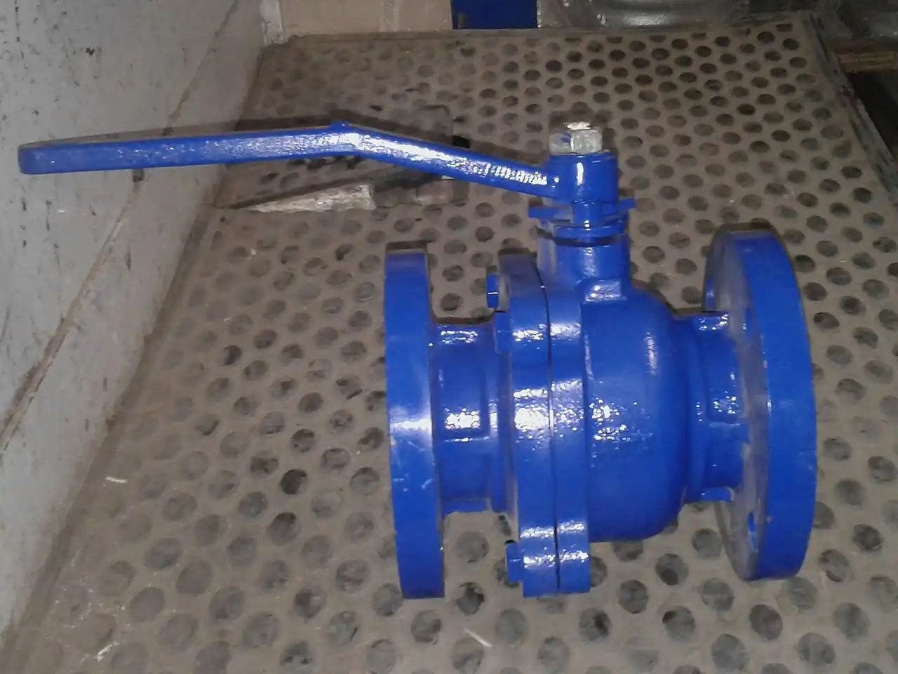
A floating ball valve is a quarter-turn isolation valve in which the ball is not fixed to a trunnion post but is free to move slightly within the body, held between two seat rings by the stem on one side and by nothing but the seats themselves on the other. When the line pressure rises with the valve closed, that pressure pushes the ball downstream into the outlet seat ring, and the seat compresses until its contact stress seals the line. The design is elegantly self-energizing: the very pressure the valve is holding provides the sealing force, and it does so without the extra bearings, journals, and springs of the trunnion mounted alternative.
Almost every small industrial ball valve is built this way. From DN 8 instrumentation isolators through DN 100 process valves and up to about DN 200 depending on class and manufacturer, the floating pattern dominates because it seals tightly at modest torque and cost. The specification questions that actually reach a buyer are: how far can the size and pressure class go before the trunnion ball valve takes over; what seat material survives the fluid and the temperature including the fire case; what torque does the closed valve demand at maximum differential so the operator or actuator is not undersized; and what does the pressure temperature derate curve allow at the top of the service range. This page answers those four questions with numbers.
This page treats the floating ball valve as a purchasing object: how the free ball and seat rings produce shutoff, where the pattern's size and class ceilings sit, which seat compounds and trims survive which fluids, what torque and derate numbers a datasheet must carry, and how to write an RFQ that separates comparable quotations from optimistic ones. It is written for engineers specifying isolation duty, not for a general reader.
Chapter 1 / 06
What a Floating Ball Is and What Is Being Decided
In a floating ball valve the closure member is a sphere, usually with a bore through it equal to or slightly less than the pipe bore, suspended between two seat rings of polymer or, in severe service, metal. The stem engages a slot or flat on the top of the ball to rotate it, but the stem carries no thrust support duty for the ball itself. The upstream seat sees roughly line pressure over the annulus of the seat; the ball is pushed downstream by line pressure acting on the unbalanced area of the ball bore, and the downstream seat carries the resulting load. This is the entire sealing concept, and it explains both the strengths and the limits of the pattern.
The strengths are real and numerous. Sealing improves with pressure, so a floating ball that is tight at low pressure is tighter at high pressure, within seat stress limits. Torque at moderate sizes stays low enough for lever operation, and the part count is small, which keeps cost and maintenance burden down. Bubble tight shutoff against soft seats is routine, meeting the zero visible leakage expectations that API 608 tested valves carry. Small bore manifolds, instrument roots, sample lines, utility stations, and process isolation up to the size ceiling are the natural territory.
The limits are equally structural. The ball load path runs through the seats, so seat stress grows with pressure times unbalanced area; at some combination of size and class the seat material yields and the valve either leaks or will not turn. That is why the trunnion ball valve exists: trunnion bearings take the hydraulic load, springs energize the seats independently of line pressure, and the ball floats on its post only enough to seat. The floating pattern's ceiling is manufacturer dependent but commonly sits near DN 200 at CL150, DN 150 at CL300, and DN 100 at CL600 in soft seat construction; above those sizes the trunnion design is standard, not a preference.
What is being decided when a floating ball valve is specified is therefore a set of commitments along four axes. First, the duty boundary commitment: staying inside the size class envelope where floating geometry is sound, and not accepting a supplier's oversized floating offer because it is cheaper, since the seat yielding failure mode arrives without ceremony. Second, the seat material commitment, which fixes fluid compatibility, temperature limits, and fire survival: PTFE family seats to about 200 deg C, polyaryletherketone family to about 250 deg C, metal seats beyond. Third, the torque commitment, because floating ball torque rises with differential pressure and seat age, and the operator, whether lever, gear, electric actuator, or pneumatic valve actuator, must be sized on the worst case. Fourth, the code commitment: API 608 for the design and test baseline, ASME B16.34 for class, API 607 or ISO 10497 for fire type testing where the process demands it, and ISO 15848 for fugitive emissions where the service is regulated.
The floating ball also lives inside a family of related leaves on this site, and the boundaries matter at RFQ time. The general ball valve page covers the quarter turn family including one piece, two piece, and three piece bodies and vented versus full bore choices. The trunnion ball valve page carries the high size and class alternative. The electric ball valve page covers the automated subset. The metal seated ball valve page carries the abrasive and high temperature seat branch. This page carries the floating seat behavior itself: how load, torque, and derate interact in the pattern that industry buys by the thousands.
Chapter 2 / 06
How the Floating Ball Seals and Operates
The seal mechanics are worth one paragraph of numbers because they predict everything else. With the valve closed, upstream pressure acts on the upstream face of the ball over the area of the bore and lands; the ball can only move downstream; the downstream seat ring must carry the unbalanced thrust, approximately pressure times the effective seat annulus area. On a DN 100 class 150 valve at 20 bar, that thrust is on the order of 15 kN. The seat ring distributes this over its contact band; so long as the resulting stress stays under the seat material's compressive limit at temperature, about 12 to 25 MPa for PTFE compounds depending on filler, the valve seals and remains operable. Exceed it and the seat cold flows, imprinting the ball and drifting toward leakage or seizure.
Torque follows the same physics. Floating valve torque has three components: bearing friction at the stem and against the downstream seat, seat friction where the ball lands wipe the seats during rotation, and the packing or O ring drag on the stem. Seat friction torque grows with differential pressure, because the ball is pressed harder into the downstream seat as pressure rises. Manufacturers publish torque versus differential curves, and the number a buyer needs for operator sizing is breakaway torque at maximum differential after dwell, commonly 1.5 to 3 times the running torque on soft seats. An actuator or gear sized on catalog "operating torque" without the dwell factor stalls on the first emergency closure, which is precisely when it must not.
Cycle behavior distinguishes good seats from cheap ones. Every quarter turn wipes the seats across the ball lands; abrasive media or weld spatter left in the line engraves the seats cycle by cycle. Soft seat floating valves in clean service reach tens of thousands of cycles; the same valve commissioning against a dirty line can lose bubble tightness in dozens. The first closure of a new valve against pipeline debris is the highest risk event of its life, which is why commissioning procedures flush before first stroke and why an upstream Y strainer on dirty services is inexpensive insurance for the seat.
Pressure and temperature derate interact through the seat. A class 300 floating valve is body rated to about 51 bar at 38 deg C in WCB, but on PTFE seats the usable pressure at 200 deg C is a fraction of that, and the vendor's pressure temperature table, not the class number, governs. Reinforced and filled seat compounds shift the curve upward at the cost of slightly higher torque; polyaryletherketone seats carry roughly 50 deg C more temperature than PTFE family at similar pressure. Cryogenic and low temperature service brings its own extended bonnet and seat material questions, and steam service above saturated pressure of about 16 bar generally leaves soft seat territory altogether.
Flow and pressure loss are usually minor selection factors but not zero. Full bore floating valves pass the pipe's own area with negligible loss, and the choice between full and reduced bore trades cost and weight against pigging and instrument insertion needs. Throttling is the persistent misuse: the ball is not a characterized closure member, the partial open position exposes the seat to high velocity cutting, and control duties belong to a control valve or globe valve built for recovery. A floating ball is a two position device, open or closed, with brief travel between; every specification that says "modulating" in the same sentence as "floating ball" is describing either a different valve or a future seat replacement.
Cavity relief is the last operating detail with purchase consequences. The closed ball traps a fluid volume in the body cavity between the seats; solar or process heating raises that cavity pressure above line pressure in liquid service, and the seats can unload or the body can be over stressed. Options are a vent hole in the upstream ball face for single direction services, or self relieving seat designs that vent cavity overpressure back to the line side. Trapped cavity pressure is a known failure mode of incorrectly specified valves in liquid and liquefied gas service, and the RFQ line is one sentence: state the required cavity relief behavior and its direction.
Chapter 3 / 06
Types, Construction, and Duty Boundaries
Body architecture divides floating valves into three families. One piece bodies are investment cast with the ball and seats inserted through one end, cheapest and non serviceable, standard in low cost utility sizes. Two piece bodies, the industrial standard, bolt a body joint around the ball and allow seat and seal replacement; the seat stack is compressed by the body joint bolts, so torque tables assume correct body bolt tension. Three piece and flanged center bodies allow full service access and bolt between pipeline flanges without disturbing the body joint. End connections span threaded NPT or BSPP to DN 50, socket weld, butt weld, and flanged ASME or EN drillings across the whole size range.
Materials follow the envelope. Bodies and balls in WCB carbon steel cover water, air, oil, and steam within class and seat limits; CF8M stainless serves corrosion and cleanliness duty; duplex 2205 and super duplex appear in seawater, sour, and high chloride services qualified to NACE MR0175 where required; nickel aluminum bronze serves marine hydraulic lines; and exotic alloys arrive by project specification. Trim matters as much as body: stems in 17-4 PH or 420 stainless, seat retainers and springs in matching corrosion grades, and packing in PTFE or graphite, with graphite mandatory on fire safe and high temperature variants. Anti static devices, a spring and ball chain tying ball, stem, and body electrically, are standard on quality valves and mandatory on hydrocarbon service in most company standards.
Seat compounds set the real service envelope. PTFE, unfilled or glass filled, dominates to about 180 to 200 deg C with excellent chemical resistance; 25 percent carbon filled PTFE wears better in slurries and higher pressure; polyaryletherketone, PEEK and related, extends to about 250 deg C with higher strength and torque; nylon seats serve low pressure fuel and water duties; metal seats, stellite or tungsten carbide coated, with graphitic or spring energized seals, carry abrasive slurry, catalyst, and steam service upward of 400 deg C and are the subject of the dedicated metal seated ball valve leaf. Fire safe constructions pair a soft primary seat with a secondary metal seal that shuts after the soft seat burns away, qualified by fire type test to API 607 or ISO 10497.
Duty boundaries are concrete and mostly load driven. Above roughly DN 200 CL150, DN 150 CL300, or DN 100 CL600, specify trunnion construction; the seat stress arithmetic no longer favors floating. High differential throttling, slurry, and dense solids are not floating soft seat duty. Trapped cavity liquids need the vent or self relief line item. Double block and bleed language belongs to trunnion twin seat designs or dedicated DBB valves; a floating ball with two seats is not a certified double block and bleed valve regardless of catalog enthusiasm. And extended service in the open position with the cavity full of corrosive media argues for drain and flush ports, a cheap option at order time and an impossible retrofit after.
The construction map below pairs the common services with the floating configuration that survives them and the configuration that returns as a warranty argument.
Service
Suitable floating configuration
Configuration to avoid
Utility water and air isolation to 16 bar
Two piece WCB, PTFE seats, lever, DN 15 to DN 100
One piece non serviceable valves at sizes the plant cannot replace quickly
Instrument root and sample isolation
Three piece CF8M, reduced bore, PTFE or PEEK seats
Soft seat valves without anti static devices on hydrocarbon taps
Diesel, lubricant, and fuel transfer
Two piece WCB or CF8M, filled PTFE seats, anti static
Unfilled PTFE seats at high pressure where cold flow imprints early
Hydrocarbon process isolation with fire risk
Fire safe API 607 qualified, graphite packing, double stem seals
Standard non fire tested soft seat valves on flammable service
Steam to about 16 bar saturated
WCB or alloy body, PEEK or metal seats, derate verified
Unfilled PTFE seats above about 180 deg C
Seawater and high chloride lines
CF8M minimum, duplex 2205 or super duplex preferred
WCB with stainless trim, crevice corrosion at seat pockets
Slurry and catalyst service
Metal seated trunnion or metal seat floating per dedicated leaf
Any soft seat floating valve in dense solids
Chapter 4 / 06
Key Specification Parameters
The decode table lists the datasheet lines that decide whether a quoted floating ball valve matches the duty; commentary follows on the lines where suppliers blur.
about minus 29 to 200 deg C soft; to 400 deg C metal
Which pressure temperature table governs
Breakaway torque
1.5 to 3 x running torque at max differential
Lever, gear, or actuator sizing without stalling
Seat leakage class
API 598 or ISO 5208 rate A soft seat; class V or VI analogs
Acceptance tightness at seat test pressure
Fire type test
API 607 or ISO 10497 qualification
Shutoff credibility after seat burnout
Cavity relief
Upstream vent hole or self relieving seats
Trapped pressure safety in liquid service
Class lines carry the most silent errors. The class fixes the body shell and joint rating per ASME B16.34, but the service point must sit under the seat derate curve at temperature, and quotations should attach the pressure temperature table for the exact seat compound offered. Two vendors at the same class can differ 30 to 40 percent in allowed pressure at 180 deg C purely through seat compound choice; the RFQ that names the seat compound instead of leaving it vendor choice gets comparable quotes.
Torque lines feed the operator decision and should be demanded as curves, not single points: breakaway and running torque at zero and maximum differential, after seat wear or thermal cycles where claimed. Manual levers carry to about DN 150 depending on class and differential; worm gear operators take over above that; automation packages, whether pneumatic valve actuator with spring return or electric quarter turn, size on the same curves with a 1.25 to 1.5 factor on breakaway. The automated subset has its own leaf on the electric ball valve page for control oriented duty.
Fire safety is binary and documentary: either the exact model carries a current fire type test certificate to API 607 or ISO 10497, or it does not. Soft seat floating valves can be fire safe; the qualification lives in the secondary metal sealing geometry and the tested construction, not in the seat compound. Hydrocarbon service company standards increasingly make this line mandatory, and "fire resistant" language without a certificate is not a qualification.
Budget planning ranges follow; figures in USD per valve for quantity one industrial quality, moving down 20 to 40 percent at project quantities.
The decision sequence compresses the page into an ordered checklist that maps line for line onto the RFQ.
Confirm the size and class sit inside the floating envelope: below roughly DN 200 at CL150, DN 150 at CL300, DN 100 at CL600 in soft seat construction; above these, move to trunnion ball valve construction and stop comparing floating offers.
Fix the fluid, concentration, and temperature envelope including cleaning cycles, fire exposure, and any trapped cavity scenario; name the seat compound accordingly, PTFE family to 200 deg C, PEEK family to 250 deg C, metal above.
Fix body, ball, and trim materials against corrosion and code requirements; CF8M as the industrial default in moist or chemical air, duplex 2205 or super duplex for chloride and sour service with NACE MR0175 conformance where the project applies it.
State the cavity relief requirement for liquid service: upstream vent hole for known flow direction, or self relieving seats for bidirectional duty.
Demand torque curves at maximum differential and size the operator with a dwell factor: lever to its limit, gear above, actuator with fail action stated.
State the fire test requirement by certificate, API 607 or ISO 10497, on all flammable service, and fugitive emission class to ISO 15848 where regulated.
State testing and certificates: API 598 or ISO 5208 seat and shell tests, EN 10204 3.1 material certificates, and the pressure temperature table for the offered seat.
State bore choice, full or reduced, from pigging and instrument needs, and end connections from the installed piping.
The recurring comparison at order time is between floating soft seat and trunnion at the overlap sizes, and the table below frames it for a DN 150 CL300 duty.
Attribute
Floating ball, soft seat
Trunnion ball valve
Seat load path
through seats, pressure energized
trunnion bearings, spring energized seats
Size ceiling, economical
about DN 150 to 200 at CL300
DN 50 to beyond DN 600
Breakaway torque at max differential
higher, pressure dependent
lower, spring dominated
Sealing tightness soft seat
bubble tight, improves with pressure
bubble tight, seat spring dependent
Double block and bleed
not certified
available in twin seat designs
Relative cost at DN 150 CL300
baseline
about 2 to 4 x
Natural duty
small bore isolation, utilities, instruments
pipelines, high class, large bore
The RFQ block for floating ball valves should read: quantity and line list with size, class, end connection, and bore; design standard API 608 or ISO 17292 with test standard API 598 or ISO 5208; body, ball, stem, and seat materials named; seat compound named with pressure temperature table attached; cavity relief behavior; fire type test certificate reference where required; fugitive emission class where required; torque data at stated differentials; operator type with fail action and accessories; and certificates: material 3.1, seat test records, and coating specification where outdoor. A quotation that answers "equivalent or better" on the seat line has not answered, and the cheapest valve that fails the derate table is the most expensive valve on the project.
Neighboring equipment lines prevent startup surprises the same way they do on every valve RFQ. If the line feeds a diaphragm pump or metering pump, state the pulsation level, because seat and packing see the pulses; if the valve sits beside a check valve on a pump discharge, state the shutoff head so the differential used for torque and derate is the credible maximum; where the same skid uses a butterfly valve for a larger cooling branch, state both so the supplier confirms the class and drilling stack across the skid; and if the scheme includes a gate valve or globe valve upstream, state the scheme so the supplier can confirm the pressure class stack is coherent. One extra sentence per neighbor converts three startup arguments into checked boxes.
Chapter 6 / 06
Installation, Standards, Failure Modes, and Maintenance
Installation practice for floating ball valves is short but consequential. Pipe strain distorts the body joint and unloads seats; support the line so the valve carries no bending. Threaded valves seal on the thread with suitable tape or compound and dielectric separation where dissimilar metals meet; flanged valves torque to the gasket pattern, not to the valve body joint. Install with the stem vertical or horizontal per the manufacturer's orientation statement, keep levers accessible, and leave the valve partially open during system hydrotest unless the test procedure says otherwise, because testing against a closed soft seat at hydrotest pressure can imprint seats before the first service day. Before first stroke, flush the line; the first closure against weld bead is the seat's worst enemy.
The standards stack is compact and citable. API 608 and ISO 17292 govern metal ball valve design and examination; API 598 and ISO 5208 govern inspection and pressure testing, with soft seat acceptance at zero visible leakage; ASME B16.34 fixes class pressure temperature for the body; API 607 and ISO 10497 govern fire type testing; ISO 15848 governs fugitive emission qualification for stems; NACE MR0175 or ISO 15156 governs sour service material selection. A complete RFQ cites the stack by number and edition year rather than by intention.
Failure modes in service cluster into six families. Seat imprint and cold flow: pressure and temperature beyond the derate table, or dwell years long, imprint the ball into the seat; remedy is seat compound upgrade at the next overhaul and derate discipline at specification. Seat cutting in throttling: high velocity partial open erodes the seat edge and ball lands; remedy is a control valve for the throttling duty and the ball for isolation. Stem leakage: packing relaxation or graphitization; remedy is packing adjustment to the vendor procedure, then seal kit replacement; on regulated service, an ISO 15848 qualified stem from the start. Cavity overpressure: trapped liquid heated by sun or process unloads seats; remedy is the vent hole or self relieving seats specified in chapter 4. Corrosion of seat pockets and body: crevice attack behind seats in chloride service; remedy is material upgrade, CF8M to duplex 2205, and drain and flush ports. Actuator undersizing: stall on breakaway after dwell; remedy is torque curve based sizing with the dwell factor, verified at commissioning by stroking against full differential.
Maintenance intervals scale with duty. Utility isolation valves in clean service: exercise annually, inspect for external leakage, repack or reseal on observation; plan soft seat renewal at major turnarounds, typically 5 to 10 years. Process valves on hydrocarbon or chemical duty: quarterly exercise where practical, annual external inspection including the body joint and any drain plugs, and diagnostic stroke testing on automated packages. Fire safe and fugitive emission qualified valves: reverify stem leakage class at major turnarounds. Every automated package adds the instrument layer checks: solenoid and limit switch function, positioner calibration, and spring return proof test on the plant's safety schedule.
Spares strategy is cheap on this valve class. A kit of seats, packing, and body joint gaskets per size, stored with the torque tables, returns most valves to new condition in a workshop hour. The planning that makes the difference is records: which valves are fire safe, which seat compound each line carries, and which torque table applies, written into the maintenance system at commissioning. The floating ball valve is a simple machine; the plants that get a decade per seat from it are the ones that specified the seat compound on paper and remembered where the paper was.
FAQ
Up to what size does a floating ball valve make sense?
As a rule of thumb, floating construction is standard to about DN 200 at CL150, DN 150 at CL300, and DN 100 at CL600 in soft seat versions, with manufacturer variation. Above those sizes the hydraulic load on the seats exceeds soft seat stress limits and the trunnion ball valve becomes the correct design, not merely an alternative. Accepting an oversized floating offer to save cost typically ends in seat cold flow and a mid project replacement.
Why is my actuator unable to open the valve after it has been closed a long time?
Breakaway torque after dwell runs 1.5 to 3 times running torque on soft seats, and it grows with differential pressure and seat age. Actuators sized on catalog operating torque stall on exactly this case. Size on the manufacturer torque curve at maximum credible differential with a 1.25 to 1.5 safety factor, and verify by stroking the assembled package against full differential at commissioning.
Which seat material should I choose for 200 deg C service?
At 200 deg C, unfilled PTFE is at or beyond its limit; use a glass or carbon filled PTFE or move to a polyaryletherketone family seat rated to about 250 deg C. Check the vendor pressure temperature table for the exact compound, because the allowed pressure at 200 deg C is a fraction of the class rating, and two compounds at the same class can differ 30 to 40 percent in allowed pressure.
Can I use a floating ball valve for throttling?
No. The ball is not a characterized closure member, and partial opening exposes the seats to high velocity cutting; a throttling floating valve loses bubble tightness quickly and often fails the seat within weeks. Use a control valve or a globe valve for regulation and reserve the floating ball for open close isolation with only brief travel in between.
What does fire safe to API 607 actually require?
It requires that the specific valve model passed a fire type test to API 607 or ISO 10497: the soft seat burns away and a secondary metal seal maintains acceptable leakage through and after the fire and cooldown, with operability retained. It is a documentary qualification by certificate, not a property of the seat material. Ask for the certificate reference for the exact model and size range in the RFQ.
Do I need cavity relief on liquid service?
Usually yes. The closed valve traps liquid in the body cavity, and solar or process heating can raise cavity pressure above line pressure, unloading seats or stressing the body. Specify either a vent hole in the upstream ball face when flow direction is fixed, or self relieving seats for bidirectional service. For gas service cavity relief is generally not required.
How long do soft seats last, and how do I plan replacement?
In clean utility service expect many years, commonly 5 to 10, between seat renewals; process service with cycles, temperature, or trace solids shortens this materially. Plan seat and packing kits per size in stores, exercise valves annually, inspect at turnarounds, and record the seat compound per line so the right kit goes to the right valve. A workshop seat change on a two or three piece body is typically a one hour job.