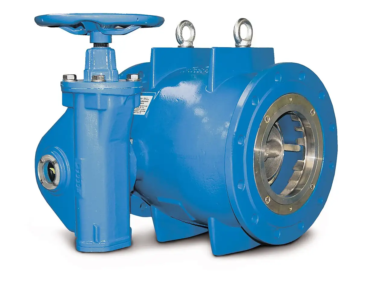
A sampling valve is a valve purpose-built to withdraw a representative, safe grab sample from a pressurized process line or vessel, without leaking process to atmosphere, without admitting outside contamination, and without altering the sample on its way to the bottle. That definition contains the whole product. An improvised sample point, a generic valve cracked open over a can, fails all three conditions at once: it vents process to air, it lets air and water hammer back into the line, and it delivers whatever was sitting in the dead leg ahead of the tap. A proper sampling valve controls the sample from the process wall to a sealed receiver, and its construction splits along the three duty worlds it serves. Process duty, on hydrocarbon, oil, and chemical streams, uses bottle probe samplers and grab sampling stations rated to extreme pressures. Aseptic duty, in pharmaceutical, biotech, and food plants, uses diaphragm sealed tank bottom valves with steam barrier ports, electropolished to sterile surface standards. Utility and boiler duty pairs the valve with a sample cooler for hot, pressurized water chemistry.
Procurement engineers usually buy these valves in dozens, one per sample point, and the decision this page settles is which duty class each point belongs to and what construction follows from it: tank bottom or in-line mounting, diaphragm or needle or bottle probe architecture, which elastomer with which certificates, whether the point needs clean in place and steam in place capability, what receiver the sample lands in, and what the whole station looks like around the valve, from first isolation to cooler to vent routing. The representativeness rules come from API MPMS Chapter 8.1 and ASTM D4057 for petroleum liquids, and the hygienic rules from ASME BPE and EHEDG practice with USP Class VI elastomers. The answer lands as an RFQ line set per sample point, and every chapter below feeds that line set.
This page treats the sampling valve as a purchasing object: what the three duty worlds demand in real numbers, how closed transfer and steam barrier designs work, what dead volume and surface finish data a datasheet must state, which standards govern representativeness and sterility, and how mount, trim, elastomer certificates, and receiver type combine into a defensible RFQ. It is written for engineers who issue purchase specifications, not for readers who want a brochure summary.
Chapter 1 / 06
What a Sampling Valve Is and What Is Being Decided
The product exists because a sample is evidence, and evidence has rules. A laboratory number is only as good as the chain that brought the fluid to the instrument, and the first meter of that chain is the sampling valve. Every design decision in this product family serves one of three obligations: representativeness, meaning the fluid in the bottle matches the fluid in the line or vessel at the moment of sampling; containment, meaning nothing escapes to atmosphere and no operator is exposed; and integrity, meaning nothing from outside enters, whether that is air into a volatile stream, microbes into a sterile broth, or rust from the tap itself. An improvised sample point fails all three quietly, which is worse than failing them loudly, because the resulting analysis still looks like data.
Process duty covers hydrocarbon, oil, and chemical service, and its hardware runs from mundane to severe. At the mild end, a grab sampling station is a small assembly of isolation, needle trim, and a vent routed to flare or vapor recovery, so the operator fills a sealed bottle without an open stream. At the severe end, autoclave style bottle valves for catalyst and petrochemical research hold process pressures to 1,000 bar class, sealing the sample inside a pressure rated receiver that never opens to air. Between those extremes sit the bottle probe samplers used on pipelines and tank farms, in which a sealed probe and bottle assembly mounts through a full bore opening, takes a fixed volume at line conditions, and comes out closed. API MPMS Chapter 8.1, the petroleum manual sampling standard, governs how the volume is taken so that water and sediment, the phases that separate fastest, are represented honestly.
Aseptic duty is a different construction world. In pharmaceutical, biotech, and food plants the sample must be sterile on both sides of the valve: the process side must not contaminate, and the sample side must not be contaminated. The standard architecture is the tank bottom sampling valve, welded flush into the lowest point of the vessel, sealed by a diaphragm rather than a sliding stem, with a steam barrier port that admits clean steam through the valve seat area between samples. Wetted surfaces are electropolished 316L to a finish of Ra under 0.8 micron, the level that ASME BPE and EHEDG guidance associate with cleanability, and elastomers carry USP Class VI certificates for contact with product. Clean in place and steam in place capability, CIP and SIP, is not an option on these valves; it is the reason they exist.
Utility and boiler duty is the third world, less exotic but higher energy. Boiler water and steam chemistry samples arrive at the tap hot and pressurized, so the station is built around a sample cooler that drops the sample below about 40 deg C before it reaches any needle trim or rotameter, with pressure reduction and a constant flow to the analyzer rack or the sample sink. The valve itself is a small bore isolation and metering assembly chosen to survive the temperature rather than to be sterile, and the station around it, cooler, pressure reducer, flow indication, does as much work as the valve.
The boundary against neighboring hardware should be drawn once, plainly, because sample points are where plants improvise. A needle valve is the generic metering isolation instrument found inside many sampling stations, but the needle valve is a component, not a sampling valve: it has no receiver interface, no purge path, and no steam barrier. A ball valve used as a crude sample tap is banned outright in pharmaceutical practice and discouraged in oil service, because its body cavity traps a pocket of old product that exits into every sample, and because hydrocarbon trapped in a cavity is a fire hazard; the legitimate use of a ball valve in sampling is structural, as the full bore entry through which a bottle probe assembly is inserted. Continuous analyzer feeds belong to the sample conditioning system, which filters, cools, and regulates a flowing slipstream to online instruments; the grab sampling valve described on this page takes a finite volume on demand. On the high pressure side, taps that must be positively isolated for probe insertion use a double block and bleed valve, and instrument grade sample taps near differential meters share the panel with an instrument manifold. Downstream of every sample point, the receiving instruments, from a pH meter to a conductivity meter in the water plant laboratory, consume what the valve delivered, which is why the valve, not the laboratory, is where a sampling program is won or lost.
What is actually being decided in this purchase is a set of five commitments per sample point. First, the duty class: process, aseptic, or utility, since nothing else follows until this is fixed. Second, the mount and architecture: tank bottom, in-line, bottle probe, or cooldown station. Third, the envelope: size, pressure, temperature, and connection standard. Fourth, the materials and certificates: body, diaphragm or trim, elastomer class, surface finish, dead volume data. Fifth, the station: first isolation, vent or drain routing, steam supply where SIP applies, cooler where temperature demands it, and the receiver type that closes the chain. A quotation that answers only the third commitment has priced a widget, not a sampling program.
Chapter 2 / 06
How Representative and Closed Sampling Work
Representativeness starts with what sits in the pipe ahead of the tap. Every sample point has a dead volume, the fluid parked between the flowing stream and the valve seat, and that fluid is yesterday's process. The first rule of grab sampling is therefore a flush: flow three to five sample point volumes to waste, or to the closed vent, before filling the receiver, so the bottle receives line fluid rather than tap fluid. The flush volume calculation is geometric, valve cavity plus nipple plus tubing, and a datasheet that cannot state its own dead volume cannot be flushed on a defensible schedule. The second rule is placement: a tap on the bottom of a horizontal line at 45 degrees into the flow sees the moving stream, while a tap on the top collects light phases and a tap on a dead leg collects neither honestly. API MPMS Chapter 8.1 and ASTM D4057 formalize these rules for petroleum liquids, including the tank mixing requirements without which a tank sample is three samples pretending to be one.
Closed transfer is the containment half of the product. In a closed sampling station the sample moves from process to receiver through a sealed path: the bottle seals onto a probe or header, the air in the transfer volume is purged out with process fluid or nitrogen, the sample enters under line pressure or displacement, and the vent, if any, runs to flare or vapor recovery rather than to the work area. Nothing opens to atmosphere at any point, so volatile organics stay in the bottle where the analysis expects them and operator exposure is engineered out instead of procedured out. For volatile and biased samples the bottle stays under a slight purge during filling, because a vacuum collapse or a bubble flash in the receiver fractionates the sample: light ends leave the liquid, the analysis reads a fluid that no longer exists in the tank.
The steam barrier is the aseptic counterpart of closed transfer. Between samples, an aseptic sampling valve admits clean steam at roughly 2 bar through the seat area, holding the flow path and the drain at about 121 deg C for 20 to 30 minutes, which is a standard SIP cycle class, and this is exactly why aseptic sampling valves carry two ports: one for steam in, one for a sterilizable drain needle out. The barrier keeps the entire wetted path sterilized between uses, so that the sample drawn today does not inherit the biology of the sample drawn last week. Before sampling, the steam is condensate drained and the valve cools, then the sample is drawn through a path that was sterile minutes earlier. Skipping the barrier cycle between samples is how a sterile facility grows a biofilm in its own sample port, and the failure mode chapter returns to that scenario with its cleanup cost.
Temperature and pressure are conditioned, not endured. Hot volatile samples go through a sample cooler that drops them below about 30 deg C quickly, because slow cooling in an open container boils off the light ends and because a warm bottle pressurizes itself. Boiler and steam samples are cooled below 40 deg C before any metering hardware, and the station takes a pressure letdown so the receiver never sees full line pressure. Pressure is also a safety boundary on the receiver: bottles and cans for liquid service carry burst disc caps or relief provisions, because a sealed liquid bottle warmed by the sun has no vapor space to absorb the expansion and will otherwise fail at its weakest joint.
Geometry inside the valve decides whether the flush rule can even work. A flush seated tank bottom valve presents no cavity to the product: closed, its seat sits level with the vessel wall, and open, the flow sweeps the whole wetted path. An in-line aseptic valve with a membrane keeps the process side smooth and drainable. A process bottle valve designs its sample path short, straight, and drainable. The common enemy is the dead leg, a pocket that neither flows nor drains, and the design response is to eliminate pockets rather than to flush them, because a pocket that must be flushed perfectly on every use is a pocket that will eventually be flushed imperfectly on one.
The safety envelope around the sample closes the chapter. Flammable service grounds and bonds the receiver before opening any path, because static generated in a splash fill is an ignition source carried to the exact point of release. Drain and vent routing is decided at purchase, not improvised: to flare, to vapor recovery, to a closed drain, or to a sterilizable drain on aseptic points. Receiver pressure ratings are matched to maximum line pressure with an interlock or procedure that prevents a low pressure bottle being presented to a high pressure point. Every one of these is a line in the RFQ, and every improvised sample point in an operating plant is evidence of a line that was left out.
Chapter 3 / 06
Types, Construction, and Duty Boundaries
The tank bottom valve is the aseptic anchor design. It welds into the lowest point of the vessel, flush seated so that closed it is part of the vessel wall and open it drains the true bottom product, and it seals with a diaphragm, typically PTFE or EPDM over 316L, actuated manually or by a pneumatic actuator. Steam connection ports on the body admit clean steam through the seat area for the SIP barrier described in chapter 2, and the drain side accepts the sterilizable needle that carries condensate and the sample away. GEMU B600 class tank valves in stainless steel are representative of the family, and the variant with a flanged or aseptic clamp outlet is the one most bioreactor and formulation vessels ship with.
The in-line aseptic sampling valve brings the same membrane philosophy to pipework. It installs in a straight run, seals with a diaphragm or membrane that isolates the actuator from product, and drains through a needle outlet that itself can be steamed. It is the diaphragm valve's close cousin and shares that family's cleanability logic: no sliding stem, no cavity, crevice free drains. Where the point must survive SIP at temperature and still give a bubble tight seal after hundreds of cycles, the diaphragm is the seal of choice, at the price of a scheduled replacement interval that chapter 6 makes routine.
Process bottle sample valves are built around the receiver rather than the vessel. A single or double block assembly seals a probe and bottle carrier onto the sample tap; with the carrier locked, an internal valve opens the process to the bottle, the bottle fills at line conditions or by displacement through a purge line, and the sequence reverses so the bottle comes out sealed with a fixed volume inside. On pipeline and terminal duty the probe enters through a full bore ball valve, which is the legitimate structural role for that valve in sampling, and on high pressure catalyst and research duty the entire receiver is a pressure rated autoclave bottle valve assembly, Parker Autoclave Engineers series class, holding up to 1,000 bar. The hermetically sealed bottle interface is the defining feature across all of them: the sample never sees air.
Sample and cooldown stations wrap the valve into the working unit a field technician actually meets. A representative station, the Swagelok grab sampling station class, pairs an isolation valve, a needle trim for metered filling, a vent to a safe destination, and a bottle or can receiver, all mounted on a bracket with the connections labeled. Boiler and utility stations add the sample cooler, a small shell and coil or tube heat exchanger dropping the sample below 40 deg C, plus pressure reduction and flow indication, so that the same point can feed both a grab bottle and the continuous rack, with a globe valve as the regulating element once the sample is cool and let down. On stations that feed online analyzers, the flowing slipstream continues downstream into the sample conditioning system, and grab sampling remains available as the check on the analyzer.
Specialty shapes complete the family. Constant pressure samplers for slurries keep the tap at line pressure through the entire sampling sequence so that dissolved gases stay in solution and particles do not flash settle, the correct instrument for tails, concentrate, and dense slurry duty. Dairy and food plants use tank samplers built to the same flush logic in product certified executions. In every case the steam and CIP supplies that serve the point are shut off by their own compact automation upstream, commonly an angle seat valve or a solenoid valve on the steam and water lines, and that automation belongs on the same purchase specification as the valve itself.
Type
Duty and mount
Typical envelope
Receiver and standard
Tank bottom aseptic valve
Pharma, biotech, food; welded flush into vessel bottom
316L electropolished, Ra under 0.8 micron; steam about 2 bar
Sterile drain needle; ASME BPE and EHEDG practice, USP Class VI elastomers
In-line aseptic membrane valve
Sterile pipework sample points
DN 8 to DN 25; SIP at 121 deg C
Sterilizable outlet; CIP and SIP capable
Bottle probe and sample valve
Pipeline, terminal, tank farm hydrocarbon
Class 150 to 600 flanged entries typical
Sealed probe bottle; API MPMS 8.1 and ASTM D4057
High pressure bottle valve
Catalyst, research, petrochemical pilot units
To 1,000 bar class
Autoclave bottle assembly; autoclave engineers series practice
Grab sampling and cooldown station
Oil, chemical, boiler water; bracket or panel mounted
Cooler to below 30 to 40 deg C; letdown to near ambient
Sealed can or bottle with purge; vent to flare or drain
Constant pressure slurry sampler
Tails, concentrate, dense slurries
Maintained line pressure through sequence
Fixed volume receiver; API MPMS 8.1 context
Boundaries deserve one blunt paragraph. The sampling valve is not a drain valve, and using the sample point to drain a vessel destroys both the valve and the sample program in one act. It is not a pressure boundary for the receiver: the receiver rating is part of the station and is matched at purchase. It does not make an unrepresentative point representative; placement, mixing, and flushing do that, and the valve only cooperates. And it is not the online analyzer's feed, which is the sample conditioning system's job: the grab valve takes a finite, evidenced volume on demand, and the two systems complement rather than substitute.
Chapter 4 / 06
Key Specification Parameters
The duty class comparison below is the first table a specifier needs, because it fixes the construction world before any single parameter is argued. The parameter table after it decodes the datasheet lines within whichever world applies.
Attribute
Process duty
Aseptic duty
Boiler and utility duty
Typical pressure and temperature
To 1,000 bar class on bottle valves; ambient to hot oil
Low vessel pressure; SIP at 121 deg C class
High steam and water pressure; sample cooled below 40 deg C
Body material
Carbon, 316, alloys per stream
CF3M or 316L, electropolished, Ra under 0.8 micron
Stroke control and interlock capability at the point
Receiver type
Sealed bottle, purge can, autoclave bottle, burst disc cap
Closed transfer integrity and pressure safety
Certificates
USP Class VI elastomers, EN 10204 3.1 material, surface report
The evidence chain behind sterility and material claims
Dead volume is the row most often omitted and easiest to demand: a stated cavity volume, in milliliters, per model and per connection configuration. Without it, the three to five volume flush rule is a guess, and with it, the operating instruction writes itself. Surface finish is the aseptic equivalent: Ra under 0.8 micron electropolished is the number that ASME BPE tables and EHEDG guidance circle, and it appears on certificates, not in adjectives. Elastomer certificates name the compound and its class, because a "food grade" EPDM without a USP Class VI or equivalent citation is a marketing phrase to a validator.
Two station rows complete the datasheet reading. Cooling duty is stated as approach and duty: what inlet temperature, what outlet below 30 to 40 deg C, at what sample flow, and the cooler lives in the same specification as the valve. Where the point also feeds continuous analysis, the flowing slipstream and its filtration and pressure regulation belong to the sample conditioning system scope, whose cabinet typically doses its reagents with a metering pump per analyzer channel, and the grab hardware, receiver, purge, and vent, stays in this purchase, with the boundary between the two scopes drawn explicitly so neither supplier assumes the other brought the cooler.
Chapter 5 / 06
Selection Decision Factors and RFQ Language
The decision sequence is short enough to run as a checklist per sample point, and each step eliminates a class of quotations before price comparisons begin.
Classify the duty: process, aseptic, or utility, from the fluid and the regulation, not from what the store has on the shelf.
Fix the mount from the source: tank bottom for vessel bottoms, in-line for sterile pipework, tap probe or station for lines, cooler station for hot water and steam.
Set the envelope: pressure, temperature, SIP exposure, and the connection standard the plant runs on, hygienic clamp, flange, or its pipe fitting and tube fitting conventions.
Choose the seal architecture: diaphragm for aseptic, needle trim for metered fills, bottle probe for sealed volume at line conditions.
Demand the data: dead volume, surface finish, elastomer certificates, SIP parameters, receiver pressure rating.
Design the station: first isolation, vent to flare or drain, steam and CIP supplies with their own angle seat valve or solenoid valve automation, cooler where temperature demands.
Name the evidence: API MPMS 8.1 and ASTM D4057 for petroleum representativeness, ASME BPE and EHEDG for hygienic acceptance, USP Class VI for elastomers.
Against neighboring hardware, the comparison a specifier actually needs runs as follows, and it belongs here in the selection chapter. The needle valve meters a fill better than any other small trim, which is why it lives inside nearly every station, but it seals against nothing beyond its own seat and belongs to this purchase only as a component, never as the whole sample point. The ball valve earns its place only as the full bore entry for a probe assembly, never as the sample tap itself, for the cavity and fire reasons chapter 1 stated. The gate valve serves as the first isolation upstream of a station on lines where the point must come out under flow, and on high pressure taps that positive isolation is a double block and bleed valve instead. The globe valve appears inside cooldown and letdown stations as the regulating element after the cooler. The diaphragm valve is the aseptic family's own architecture, and the sampling valve built on a membrane is its sampling expression; pressure and temperature ceilings follow the elastomer. The angle seat valve and the solenoid valve automate the steam, CIP, and purge supplies around the point and do not touch product. A Y strainer on the supply side of cooling water and on instrument feeds protects seats from particles that would scar them, though never on the sample path itself, where it would become the dead leg this page keeps warning about. Downstream, the metering pump doses reagents into online analyzer streams and the sample conditioning system carries the continuous feed; the grab valve's customer at the end of the chain is the laboratory, whose pH meter and conductivity meter calibrations are validated against exactly the volumes this valve delivers. Choose the point from the chain it serves, not from the valve a supplier has in stock.
The application map below turns those boundaries into a table the project file can carry.
Application
Construction to specify
Check before order
Bioreactor or formulation vessel, sterile
Tank bottom diaphragm valve, electropolished, SIP ports, sterilizable drain
Ra under 0.8 micron certificate; USP Class VI elastomers; diaphragm spares
Sterile process pipe sample point
In-line aseptic membrane valve with steam barrier
Barrier steam supply and drain routing; CIP compatibility
Crude or product pipeline grab
Bottle probe through full bore entry; sealed carrier
API MPMS 8.1 probe placement; grounding; carrier pressure rating
High pressure catalyst sampling
Autoclave style bottle valve assembly
Receiver rating to line pressure; interlock; burst disc provision
Boiler water and steam chemistry
Station with sample cooler, letdown, needle trim
Cooler duty to below 40 deg C; constant flow; sink or analyzer split
Slurry and tails duty
Constant pressure sampler
Line pressure held through sequence; wear parts schedule
Online analyzer tap with grab backup
Station beside a sample conditioning system tap
Scope boundary drawn: cooler and fast loop ownership explicit
The RFQ block should be written once per point class and reused. A complete block reads: service class and fluid, with solids, volatility, and sterility stated; tank or line mount with orientation; size, pressure class, and temperature including SIP exposure; connection standard, aseptic clamp DIN 11864 or TC, flange drilling, or tube fitting type; body material and finish with certificate, electropolished 316L Ra under 0.8 micron where aseptic; diaphragm or trim material with elastomer certificates, USP Class VI where pharma; SIP and CIP capability with steam port size and drain acceptance; dead volume data per model; receiver type with pressure rating, burst disc provision, purge connection, and material; actuation with fail action where automated; station scope, first isolation type, vent routing, cooler duty where hot; automation scope for steam and purge including any angle seat valve or solenoid valve; representativeness and hygiene evidence, API MPMS 8.1 and ASTM D4057 for petroleum, ASME BPE and EHEDG practice for hygienic; and material certificates EN 10204 3.1 across wetted parts. A quotation returned without dead volume data or the elastomer certificate is incomplete at any price.
Chapter 6 / 06
Installation, Standards, Failure Modes, and Maintenance
Installation decides whether the geometry promises of the datasheet survive contact with the pipe. Tank bottom valves weld flush at the vessel's true low point, on the slope, so the vessel drains through them rather than past them; a point placed beside the low point collects what settles nowhere. Line points mount at 45 degrees into flow on the bottom of horizontal runs, never on top where light phases gather. Steam barrier plumbing runs short, sloped, and condensate drained, because a barrier that holds condensate holds exactly the cold spot a SIP cycle is supposed to eliminate. Sample tubing is instrument grade, assembled with the matching tube fitting throughout rather than mixed threads, the station's process side joins follow the plant pipe fitting standard, and the whole run is supported so it drains toward the receiver or vent without traps. First isolation, a gate valve or line standard valve upstream, sits where a technician can reach it with the receiver in place, every vent and drain lands somewhere named on the drawing, and analyzer panels nearby keep their own instrument manifold hardware for the differential meters so sample tubing and impulse tubing never share a route.
Commissioning proves the chain end to end. Flush the point and tubing before the first sample and record how many volumes it took; verify the cooler holds the sample below its stated temperature at working flow; on aseptic points, run a full SIP cycle, let it fail cool, and sample the drain; on closed stations, leak test the receiver interface at line pressure with gas before the first fluid. Label the point with its flush count and its receiver type, because the field technician three years from now has only the label. Where the point feeds a laboratory, file the commissioning sample against the laboratory's own baseline so the analytical chain starts with evidence.
The standards set the verification frame, and the RFQ quotes them by name. API MPMS Chapter 8.1 governs manual sampling of petroleum liquids, probe placement, mixing, and the representativeness logic behind every hydrocarbon grab. ASTM D4057 is the parallel practice for petroleum manual sampling. ASME BPE carries the hygienic design, finish, and acceptance expectations for bioprocessing hardware, EHEDG documents 8 and 10 the hygienic sampling context in Europe, and USP Class VI is the elastomer toxicity citation validators ask for by number. Material certificates follow EN 10204 3.1. A datasheet that cites none of these is a price tag with a part number on it.
Failure modes in service follow a short and predictable list. The diaphragm pinhole leads the aseptic list: a microscopic breach passes product behind the membrane, a biofilm establishes in the cavity, and the fix is replacement followed by a full SIP cycle, not a wipe. Seat scarring from particulates comes next on process duty, read as a slow drip at a valve that used to hold, prevented by keeping solids out of the tap with placement and procedure and by a Y strainer on the utility supplies that feed it. Steam port clogging shows as barrier pressure that will not hold or drain flow that stops, and the response is descaling the port and needle. Sample cooler fouling reads as outlet temperature creep, and every degree of creep is light ends boiled off on volatile service, quietly biasing every analysis downstream. Receiver overfill or overpressure is prevented, not managed: burst disc caps, purge provisions, and a receiver rated for the point. Dead leg contamination is designed out in chapter 2 and stays out only if the flush count on the label is honored; when a point is found with old product in it, the flush procedure is the first thing to audit.
The maintenance program is short enough to run on a card. Diaphragms replace on a 6 to 12 month interval, or immediately on any suspicion of damage, and the spare is on site because the alternative is an out of service sample point during a batch. Steam gasket seats and the sterilizable drain needle inspect at the same interval, and the actuator, where pneumatic, gets its standard service. Automated steam, CIP, and purge lines service their own solenoid valve and angle seat valve elements on the utility schedule. Coolers clean and test on the temperature evidence, tubing and receivers on visual inspection, and elastomer lots on expiry. The laboratory side of the chain carries its own discipline: instruments that receive the samples, the pH meter, the conductivity meter, and their calibration schedule, are audited against check samples delivered through the same valves, which closes the loop between the valve program and the analytical program.
Close the lifecycle with records the next RFQ can use. Keep per point: the datasheet with dead volume, the commissioning flush count and leak tests, the diaphragm and elastomer replacement dates with lot numbers, the cooler temperature trend, and every finding. When the next facility is specified, that file converts supplier claims into line items: measured diaphragm life sets the spares ratio, cooler fouling history sets the cleaning interval, and the failure log sets the geometry rules. A sampling program that cannot show those numbers is analyzing whatever the tap happened to hold, and the file that proves otherwise is how a purchasing specification gets smarter instead of just older.
FAQ
What is the difference between a sampling valve and a needle valve?
A needle valve is a generic metering and isolation component with fine stem control over flow, and it appears inside many sampling stations. A sampling valve is a purpose-built assembly for withdrawing a sample: it adds the sealed receiver interface, purge and vent paths, and on aseptic designs the steam barrier ports that sterilize the path between uses. The needle valve meters the fill; the sampling valve owns the whole chain from process wall to sealed bottle.
What do CIP and SIP capability mean on a sampling valve?
CIP, clean in place, means the valve cleans in the installed position with flushing chemicals and no disassembly. SIP, steam in place, means the wetted path sterilizes with clean steam, typically about 2 bar and 121 deg C for 20 to 30 minutes, admitted through the steam barrier ports and drained through a sterilizable needle. This two port arrangement is what lets an aseptic sampling valve sterilize its entire flow path between every sample.
How do I take a representative sample from a pressurized line?
Flush the sample point three to five of its own volumes to waste or a closed vent before filling, so the bottle receives line fluid rather than what sat in the tap. Mount the tap at 45 degrees into flow on the bottom of the run, ensure the source is mixed, and draw into a sealed receiver under closed transfer. For petroleum liquids, API MPMS Chapter 8.1 and ASTM D4057 fix the placement, mixing, and procedure details.
Why is a ball valve a poor choice as a sample tap?
A ball valve traps a pocket of product in its body cavity when it closes, and that pocket exits into the next sample, so the analysis reads stale fluid. In pharmaceutical practice such sample points are banned outright, and in oil service the trapped hydrocarbon cavity is also a fire hazard. The legitimate sampling role of a ball valve is structural, as the full bore entry through which a sealed bottle probe assembly is inserted and retrieved.
Which connection standard should an aseptic sampling valve use?
Match the plant standard and name it in the RFQ. Common executions are aseptic clamp connections to DIN 11864, tri clamp style flanges, and hygienic weld ends, on electropolished 316L with a surface finish of Ra under 0.8 micron certified to ASME BPE practice, with EHEDG guidance as the European reference. The connection is part of the cleanability claim: mismatched joints create the crevices the finish was specified to avoid.
How often should the diaphragm on an aseptic sampling valve be replaced?
Plan replacement every 6 to 12 months of service, or immediately on any sign of damage, and keep the spare on site. A pinhole diaphragm passes product behind the membrane and lets a biofilm establish in the cavity, so replacement must be followed by a full SIP cycle before the point returns to service. Log the replacement date and elastomer lot number per point, since validators ask for that history.
What receiver should I use for volatile hydrocarbon samples?
Use a sealed bottle or can that closes onto the station interface, filled under closed transfer with a slight purge so light ends stay in the liquid, vented only to flare or vapor recovery. Ground and bond the receiver before opening any path, and fit burst disc caps or relief provisions, because a sealed liquid bottle that warms has no vapor space to absorb expansion. For hot streams, cool the sample below 30 deg C quickly through a sample cooler before it enters the receiver.