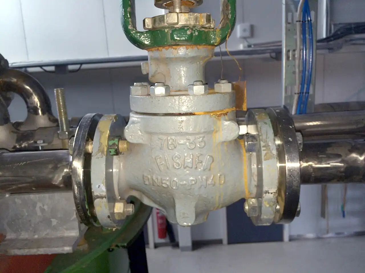
A segmented ball valve is a quarter-turn rotary control valve whose closure member is a partial ball, a segment of a ball shell carried on a shaft across the flow passage, closing against a single seat. As the shaft rotates toward closed, the segment cams into the seat and generates its own seating load; as it opens, the segment cams clear within the first few degrees of travel, so the seat is not scrubbed through the stroke, and the leading edge of the segment shears fibers, pulp, and soft solids instead of collecting them. The geometry is the Fisher Vee-Ball V150, V200, and V300 class: flanged, flangeless, and high class bodies spanning DN 25 to DN 600, CL150 to CL600, with a DN 50 full-open Cv near 170 and FCI 70-2 class VI shutoff on soft seats.
Procurement engineers meet these valves on paper machine stock and consistency control at 2 to 5 percent consistency, on wastewater digester sludge recirculation, on latex, starch, and polymer dosing, on mining and flue gas scrubber slurries, and on water distribution pressure control where one station must throttle a wide turndown at high capacity. The decision this page settles is whether the loop should be served by a partial ball trim, which characterization the segment should carry, and what seat, body, and actuator package survives the fluid. The answer lands as an RFQ line set, size and characterization and Cv and leakage class and seat material and actuator with fail action, and every chapter below feeds that line set so the loop is bought, not hoped for.
This page treats the segmented ball valve as a purchasing object: what the partial ball and its cam action change in real torque and capacity numbers, how characterized segments map onto loop gain, where soft seats end and coated metal trims begin, and how seat class, body execution, actuator, and fail action combine into a defensible RFQ. It is written for engineers who issue purchase specifications, not for readers who want a brochure summary.
Chapter 1 / 06
What a Segmented Ball Valve Is and What Is Being Decided
The closure member is the difference from the familiar isolation valve. A plain ball valve drills a full bore through a complete sphere and exists to be either open or shut; pressed into modulating duty it behaves like a quick opening switch, with most of its flow arriving in the first third of travel. A segmented ball valve keeps the quarter-turn shaft but replaces the full sphere with a partial shell, roughly a half ball or less, contoured so that the flow window grows on a designed curve as the shaft rotates. The trim is therefore a control valve first and an isolation element second: the geometry of the segment, not the bore diameter, sets the relationship between shaft angle and flow, and that relationship is what the buyer is really specifying.
What is actually being decided in this purchase is a package of three commitments. First a capacity commitment: partial ball trim passes roughly three times the flow of a same-size conventional globe body, so the size choice changes and with it the pump head and the pipe spool. Second a service commitment: the single seat and the shearing segment edge are the reason this trim survives fibrous stock and sludge that would wrap a plug or pack a cage, and the seat material decides whether that survival lasts years or months. Third an actuation commitment: the valve is bought as a package with an actuator and positioner, because a segment left to a lever or to an unpositioned cylinder is an open loop guess. A quotation that prices the body and leaves the rest as an exercise is not a quotation.
The duty context is what makes the trim worth its premium. Paper stock lines carry fibers at 2 to 5 percent consistency that bridge and hang on any recess; digester sludge carries strings and grit; latex and polymer dosing carry viscoelastic fluids that string through narrow gaps; scrubber and mineral slurries carry abrasive solids. In each case the flow area of a segment trim is an open swept passage with no pockets, and every stroke wipes the seat clean. The same stations also sit between process elements: upstream of a static mixer, downstream of a pump whose shutoff head sets the worst credible differential, next to a butterfly valve on large headers, a manual globe valve at local sampling points, or a needle valve on small vents, in a loop closed by the plant control system.
Four standards organize the datasheet. Sizing language comes from the ISA-75 series: ISA-75.01 defines the flow coefficient Cv, the liquid pressure recovery factor FL, and the pressure drop ratio Xt used in every calculation, and ISA-75.02 defines how capacity is tested to certify those numbers. Seat leakage classes come from FCI 70-2, where class VI means bubble tight soft seat shutoff and class IV defines the metal seat allowance. Body walls and pressure temperature ratings follow ASME B16.34 by class, and flanged face-to-face dimensions follow ISO 5752 so a replacement fits the spool. A datasheet that quotes none of these four is a price tag, not a specification.
Chapter 2 / 06
How the Partial Ball and Cam Action Shape Control
Mechanically the trim is a rotating wedge with one sealing face. The segment is carried on a shaft set across the bore; the shaft axis and the ball center are offset, so rotating the shaft toward closed swings the spherical face of the segment into the seat ring along a cam path, converting shaft torque directly into seating load. At closure the load is at its maximum and the seat seals with line pressure assisting from upstream. On opening, the first few degrees of rotation lift the segment face clear of the seat, and the remaining 80 degrees of travel run against bearings and packing only. This camming action is why segmented torque peaks at breakaway and then falls, why the seat wears evenly along its face instead of grooving at one land, and why the trim tolerates thousands of strokes in abrasive service that would destroy a sliding plug.
The leading edge of the segment is the shear edge, and it is the reason this trim owns fibrous duty. As the segment closes, that edge passes across the seat like a blade, cutting fiber bundles, strings, and soft agglomerates and flushing them downstream instead of trapping them in the sealing land. Paper stock, digester sludge, and polymer strings that hang on every recess in a cage trim meet an open passage and a wiping edge instead. The same edge concentrates wear in abrasive slurries, which is why abrasive duty moves the specification toward coated segments and metal seats in chapter 3 rather than away from the trim.
Capacity is the headline number. Because the segment presents a large open flow passage with minimal obstruction, a DN 50 body in the V150 class carries a full-open Cv near 170, representative figures for the family run near 650 at DN 100 and 2,600 at DN 200, with maker variation of roughly plus or minus 25 percent, so the quoted Cv table must be checked per size. The consequence at station level is capacity in a smaller body: loops that would otherwise need a larger, heavier, more expensive conventional trim often pass at one size smaller with a segment, which recovers part of the premium at the pipe spool. The number to demand with the capacity table is Cv versus travel at fixed steps, because the modulating decision is made at the operating point, not at full open.
Characterization is machined into the segment contour. The standard contour of a Vee-Ball class segment approximates an equal percentage characteristic: each equal increment of travel increases flow by a roughly constant ratio, so loop gain stays flat when most of the system pressure drop lies elsewhere in the circuit, which is the common case on stock and sludge headers fed by pumps. A linear characterized segment, machined with a wider, differently curved window, gives flow directly proportional to travel across the middle band and suits blending and level duty where the valve takes most of the drop. Specifying the characteristic is a control decision made against the process gain curve, and the two options should appear as line items in the RFQ, not as catalog footnotes.
Sizing follows ISA-75.01 with the recovery factors published for the trim. The partial ball is a high recovery geometry: static pressure falls well below the outlet pressure at the segment vena contracta and recovers downstream, and the published FL sits near 0.6 with Xt near 0.55, values that must be run through the cavitation and noise check before the valve is bought. On liquid letdown at high differential this trim cavitates earlier than low recovery designs, and the remedies are structural: share the drop across two valves or with an orifice, or specify the station differently in the selection chapter. Gas and vapor duty adds aerodynamic noise, predicted with the same sizing framework and managed with outlet diffusers or heavier pipe where the calculation says so.
Torque decides the actuator, and the cam gives it a favorable shape. Breakaway torque to shear the seat and start the segment is the peak; travel torque through the open band is low because the segment rides on bearings, and hydrodynamic torque from flow acting on the segment can act with or against the motion depending on flow direction. Modulating duty therefore pairs the body with a rack and pinion pneumatic valve actuator sized on breakaway at maximum differential with a 1.25 to 1.5 safety factor, closed loop through a digital valve positioner that strokes the shaft against the controller signal. An electric actuator with profile control suits slower loops and remote sites without air; either way the positioner, not the actuator alone, is what makes the valve a control instrument.
Chapter 3 / 06
Types, Construction, and Duty Boundaries
Three body executions cover the market, and the Fisher Vee-Ball families map them cleanly. The flanged one-piece body, the V150 class, bolts between pipe flanges and is the general purpose execution through CL300. The flangeless wafer body, the V200 class, is clamped between the line flanges by the through bolts, shortens the spool, saves weight and cost, and dominates large water and stock lines where every kilogram counts. The heavy flanged body, the V300 class, carries CL600 pressure ratings and the thicker walls and larger shafts that go with them. A fourth construction distinction matters for maintenance: side entry split bodies open on a bolted seam so the seat, seals, and shaft come out without cutting the valve out of the line, which on a sludge header is the difference between a shift and a day.
Materials follow the service, and the list is short. Bodies and end flanges are WCB carbon steel for utility duty, CF8M stainless steel for stock, chemical, and anything corrosive, and duplex 2205 for high chloride and abrasive white water duties. Shafts run 17-4 PH precipitation hardening stainless in standard builds, sized in shear because the segment hangs the hydraulic load entirely on the shaft and its bearings; the bearings themselves are composite or hardened sleeves, and their wear shows up as shaft play before it shows up as leakage. Segment coatings are where abrasive duty is won or lost: hard chrome or tungsten carbide on the seating face and shear edge holds the characteristic for years where an uncoated segment loses it in months.
Seats set the leakage and temperature envelope. Soft seats of PTFE or filled PTFE cover minus 29 to 200 deg C, hold FCI 70-2 class VI bubble tight shutoff, and suit most stock, sludge, and water duties; PEEK seats extend to about 250 deg C and resist cutting at the shear edge in gritty service. A metal seat execution, coated segment seating onto a coated seat ring, runs hotter and survives abrasive slurries and high cycle counts, and its leakage acceptance drops to class IV with a defined allowable rate, which must be accepted in the specification rather than discovered at factory test. The seat line on the datasheet is two decisions at once, temperature limit and leakage limit, and a weak answer on either is a reject flag on the quotation.
Boundaries are worth stating bluntly. This valve is not a safety device and never substitutes for a relief valve on any line. It is not the right instrument below about Cv 1, where a needle valve meters with far finer resolution. It should not take a full liquid letdown drop in one stage at high differential, for the recovery reasons in chapter 2. And if the duty is two-position switching with an occasional stroke, a plain ball valve at a fraction of the price is the honest purchase: the characterized segment earns its premium only when the loop lives inside the throttling band for hours at a time. A small manual globe valve remains the right tool for local sampling and vent points around the station, where its fine thread beats any quarter turn.
The duty map below consolidates the boundaries into one table a specifier can scan before writing the RFQ; it pairs common services with the construction that survives them and the construction that generates callbacks.
Service
Suitable construction
Construction to avoid
Paper stock dilution and consistency control, 2 to 5 percent
Cage or plug trim without relief (fibers wrap the plug)
Digester and WWTP sludge recirculation
Segmented trim with hardened shear edge, flush ports, stainless steel fasteners
Soft seat without cycle evidence at solids loading
Latex, starch, and polymer dosing
Linear segment, PTFE seat, polished CF8M wetted path
Recessed cavities that let viscoelastic fluid string and bridge
Mineral tailings and scrubber slurry
Metal seated execution with tungsten carbide coating, class IV accepted
Uncoated segment and soft seat (edge cuts through in weeks)
Water district pressure control, DN 100 to DN 400
Flangeless wafer body, positioner, sealed stem per ISO 15848 where audited
Oversized segment running below 10 percent travel at night flow
Spray quench and fill and dump duty
Linear or standard segment, spring return actuator for fast fail
Equal percentage segment where full capacity is needed within seconds
Two-position isolation with rare stroke
Plain full-bore ball valve
Segment premium spent on a duty that never throttles
Chapter 4 / 06
Key Specification Parameters
The table below decodes the datasheet lines that decide whether a quoted valve matches the service. Each row is a purchase defining parameter; the paragraphs after the table explain what to demand and what a weak answer looks like.
Attribute
Typical range or options
What it decides
Nominal size
DN 25 to DN 600, control volume DN 40 to DN 300
Pipe schedule, flange drilling, spool length, and actuator torque class
Pressure class
CL150, CL300, CL600; PN16 to PN100 equivalents
Body rating per ASME B16.34 and the seat derate applied at temperature
Body execution
Flanged V150 class; flangeless wafer V200 class; heavy flanged V300 class
Spool fit, weight, maintenance access, and pressure ceiling
Full-open Cv, representative
DN 50: 170; DN 100: 650; DN 200: 2,600; maker variation plus or minus 25 percent
Station capacity and whether one size smaller covers the duty
Segment characterization
Equal percentage standard contour; linear characterized segment
Inherent characteristic and loop gain through the throttling band
Leakage class
FCI 70-2 class VI soft seat; class IV metal seat
Acceptance test applied at the seat during factory test
Seat and temperature
PTFE minus 29 to 200 deg C; PEEK to 250; carbide metal seat beyond
Seat compound, derate curve, and shutoff credibility at heat
Corrosion envelope, abrasion life, and shaft strength in shear
FL and Xt per ISA-75
FL near 0.6; Xt near 0.55, published per travel
Cavitation and noise check before the valve is bought, not after
Actuation
Rack and pinion pneumatic with positioner; electric; hydraulic; scotch yoke at DN 300 plus
Torque delivery, control signal match, and fail action
The Cv row deserves its own paragraph because it is the row most often misused. Manufacturers quote full-open Cv because it flatters the valve, but a modulating selection is made at the operating point: demand the Cv versus travel table at fixed steps, 10 through 90 degrees or the percentage equivalents, and verify that normal flow lands between 20 and 70 percent travel. An oversized segment behaves like a quick opening valve with a resolution problem, and no positioner tuning recovers what the size choice destroyed. The companion number is the minimum controllable Cv implied by the rangeability claim, quoted from 150:1 to 300:1 across the family, which must sit below the minimum process flow with margin, or the loop will spend every night cycling against a valve that cannot resolve small moves.
The FL and Xt row is the cavitation and noise gate. The ISA-75.01 calculation uses FL to compare the allowable pressure drop at service temperature against the required drop, and a quotation without published FL at travel is silent exactly where the risk lives. Ask for FL at the expected travel band, not the single catalog value, because recovery behavior changes as the segment opens. The characterization table below compresses the trim contour decision into the form a control engineer can argue from in a specification meeting.
Trim geometry
Inherent behavior
Where it earns its cost
Equal percentage segment, standard contour
Constant ratio gain per travel increment
Stock, sludge, and pressure loops where system drop dominates
Linear characterized segment
Flow proportional to travel through mid band
Blending, level, and fill duty where the valve takes the drop
Coated metal seat segment
Any contour, class IV leakage
Abrasive slurry and high cycle duty beyond soft seat life
Segment with hardened shear edge
Contour unchanged, edge life extended
Fibrous stock where edge rounding shifts low travel flow
The actuation row closes the specification. Modulating duty means a pneumatic valve actuator with a digital positioner matched to the controller signal, spring return to the fail position that protects the process, and limit or position feedback where operations audits the loop. An electric actuator suits remote stations and slower loops and must be checked against stroke frequency and duty cycle. Where torque demand is extreme or instrument air is unavailable, a hydraulic valve actuator delivers force in a compact package and holds position under vibration that would make an undersized cylinder hunt. From about DN 300, a scotch yoke actuator converts cylinder or motor torque into the quarter turn more efficiently than rack and pinion, and ISO 5210 or ISO 5211 mounting keeps the package interchangeable when the actuator is replaced years later.
Chapter 5 / 06
Selection Decision Factors and RFQ Language
The decision sequence is short enough to run as a checklist in a specification meeting, and each step eliminates a class of quotations before price comparisons begin.
Confirm the duty is genuinely modulating: if the valve switches rather than throttles, buy a plain ball valve and stop reading.
Define the fluid honestly, including fibers, strings, crystals, and solids: consistency percentages and particle sizes decide seat and coating, not brochure chemistry.
Compute the maximum credible differential, including pump shutoff head, and run the ISA-75.01 cavitation check with the quoted FL before, not after, selection.
Set the temperature envelope with cleaning cycles if any, then pick the seat: PTFE, filled PTFE, PEEK, or a coated metal seat.
Choose the segment characterization against the process gain, equal percentage or linear, and write it into the RFQ by name.
Size on the operating point: full-open Cv plus the Cv versus travel table, with normal flow between 20 and 70 percent travel.
Package the actuation: actuator sized on breakaway at maximum differential with the 1.25 to 1.5 factor, positioner matched to the PLC signal, fail action stated, feedback listed.
Fix the verification evidence: capacity test basis, seat leakage test, FL and Xt at travel, derate table, and material certificates.
Against the neighboring trims, the comparison a specifier actually needs runs as follows, and it belongs here in the selection chapter. The globe control valve is the reference modulating instrument: its plug trims absorb high pressure drop with FL near 0.9, resist cavitation, and meter the smallest flows, but a same-size globe control valve body passes far less, roughly Cv 60 where a DN 50 segment passes 170, so high capacity or fibrous duty usually lets the segment win one or two sizes smaller, at lower weight and lower cost per unit of Cv. The V-port ball valve, a notched full ball seating against two seats, holds finer low travel resolution and symmetric sealing, and is the better purchase in loops that live below 10 percent opening; the segment answers with lower torque, one seat to maintain instead of two, and easier seat renewal, which is why it dominates large lines and abrasive stations. The butterfly valve wins on installed cost and weight from about DN 400 in clean water duty with modest shutoff demands. The needle valve owns everything below about Cv 1. Choose the trim the loop and the fluid demand, not the type a supplier has on promotion.
The application map below turns that comparison into a table the project file can carry.
Breakaway torque with fiber loaded seat; seat resiliency at duty temperature
Digester sludge recirculation and transfer
Hardened shear edge, stainless steel internals, spring return actuator
Cycle life evidence at solids loading; flush port provision
Polymer and latex dosing with wide turndown
Linear segment, PTFE seat, polished CF8M path
Minimum controllable Cv against smallest dose; class VI between doses
Water district pressure control
Flangeless wafer body DN 100 to DN 400, positioner, sealed stem
Night flow minimum against rangeability floor; cavitation check at shutoff head
Scrubber and tailings slurry
Carbide coated metal seat segment, class IV accepted in writing
Coating specification and wear warranty against particle loading
High drop liquid letdown, single stage
Stage two valves or share the drop with an orifice
Any segment alone at 8 bar or more drop without the FL check
The RFQ block should be written once and reused. A complete block reads: quantity, size, and class with flange drilling or wafer dimensions; body execution named, flanged, flangeless, or side entry; segment characterization by name; required Cv at maximum and normal flow with the operating point stated; rangeability requirement with the minimum controllable Cv; leakage class and test basis to FCI 70-2; fluid with fiber and solids loading stated in numbers; minimum and maximum temperature with cycles; maximum steady and transient differential; seat, body, segment coating, and shaft materials; actuator type with fail action, positioner signal type from the PLC, typically 4 to 20 mA, and feedback accessories; face-to-face per ISO 5752 where flanged; and certificates, capacity test to ISA-75.02, seat test to FCI 70-2, material certificates EN 10204 3.1. Pair the station with an upstream pressure transmitter so the differential and any cavitation onset are visible to the control room, and the quotation returned without the Cv table or FL data is incomplete at any price.
Chapter 6 / 06
Installation, Standards, Failure Modes, and Maintenance
Installation quality decides whether the trim reaches its catalog life. Respect the flow direction arrow, because the seat is downstream and the cam geometry assumes pressure from the defined side; a segment installed backwards seats against the wrong face and leaks from the first stroke. Mount the actuator per the ISO 5211 or 5210 dimensions with the stem horizontal or as the maker allows, and support heavy actuators on DN 200 and above so the load never hangs off the valve bonnet alone. Bring wafer bodies up evenly on the through bolts, and torque a flange joint to the supplier table, because an over-torched flange distorts the body shell and the seat ring with it. Give the station the same straight run respect as any control element, about 5 pipe diameters clear of elbows and pumps, less for the valve than for the flow measurement the loop tunes against.
Commissioning protects the seat and the loop. Flush the line before first stroke, because the first closure of a segment against weld spatter engraves the seat land for the rest of its life, and a commissioning strainer is cheaper than a seat. Stroke the valve across full travel with the positioner in manual, record the actual 0 and 100 percent points, the deadband, and the hysteresis, and reject a package showing more than 2 to 3 percent hysteresis, which points at packing, bearings, or linkage. Verify the fail action by bleeding the actuator, not by trusting the nameplate, and check the 4 to 20 mA loop from the PLC end to end, signal to travel, at 25, 50, and 75 percent, filing the results as the baseline signature for condition monitoring.
The standards set the verification frame. ISA-75.01 and ISA-75.02 fix the sizing equations and the capacity test method behind every Cv and FL figure. FCI 70-2 defines the seat leakage classes quoted on the test certificate. ASME B16.34 governs wall thickness and pressure temperature ratings by class, and ISO 5752 keeps flanged face-to-face dimensions interchangeable. ISO 5211 and ISO 5210 fix the actuator interface. Where the service carries fire risk, API 607 or ISO 10497 qualification must be demanded explicitly, because a soft seated body carries none by default, and where the site audits fugitive emissions, ISO 15848 stem testing replaces the default packing acceptance. Citing the standards by name in the RFQ transfers the burden of proof to the supplier, which is where it belongs.
Failure modes in service follow a short and predictable list. Shear edge and seat wear: fibers and grit round the edge and cut the seat land, leakage rises first at low differential, and the Cv versus travel curve drifts so the loop slowly retunes itself around a damaged instrument; the fix is seat or coated segment renewal, planned at the first drift signal rather than at failure. Shaft and bearing wear: play appears, hysteresis grows, and on large bodies the segment can rock off the seat under pulsation; detected by the annual stroke test. Packing leakage: adjust or replace, and upgrade to a low emission set on hot or audited services. Cavitation damage: pitting downstream of the segment edge, audible as gravel in the pipe, remedied by staging the drop or sharing it with an orifice. Positioner faults: hunting from a feedback linkage worn past its adjustment range, and stalls from an actuator undersized after a seat ages and breakaway torque rises. A pressure transmitter trend on the station differential catches the cavitation margin eroding before the metal shows it.
Maintenance intervals scale with duty severity. Sludge and slurry service deserves a stroke and hysteresis check quarterly and a seat inspection at every planned shutdown, with seats treated as consumables in the spares budget from day one. Clean water modulating duty stretches the same checks to annual, plus packing adjustment and a torque trend where the actuator reports one. Every valve that throttles continuously earns an internal inspection at the first major shutdown after three years regardless of apparent health, because a drifting characteristic curve is invisible from outside the loop until it is not. Feed the findings back into the next RFQ as line items, and the purchasing file gets smarter instead of just older.
FAQ
How does the camming action of a segmented ball valve work?
The segment is carried on a shaft set slightly offset from the ball center, so rotating the shaft toward closed swings the spherical face along a cam path into the single seat, converting torque directly into seating load. On opening, the first few degrees lift the segment clear, so most travel runs on bearings only. Torque peaks at breakaway and then falls, seat wear spreads evenly, and the trim tolerates thousands of strokes in abrasive and fibrous service.
What Cv can I expect from a segmented ball valve?
Representative full-open figures for the family are Cv near 170 at DN 50, 650 at DN 100, and 2,600 at DN 200, with maker variation of roughly plus or minus 25 percent, so always demand the Cv table for the quoted size. The practical consequence is capacity in a smaller body: many stations pass one size smaller than a conventional trim would need. Size on the operating point, with normal flow between 20 and 70 percent travel, not on the full-open ceiling.
Can the trim pass fibers and sludge without hanging up?
Yes, that is its home duty. The flow path is an open swept passage with no recesses, and the leading edge of the segment acts as a shear edge, cutting fiber bundles, strings, and soft agglomerates as it closes and flushing them downstream. Paper stock at 2 to 5 percent consistency, digester sludge, and polymer strings that wrap a plug meet a wiping edge instead. In gritty service, specify a hardened edge and coated seat to keep that advantage for years.
What leakage class does a segmented ball valve achieve?
Soft seats of PTFE, filled PTFE, or PEEK test to FCI 70-2 class VI, effectively bubble tight, which is the normal line on stock, sludge, and water duty. Metal seat executions with carbide coated faces, chosen for abrasive slurry, high cycle counts, or temperatures above soft seat limits, test to class IV with a defined allowable rate. State the required class and test basis in the RFQ so the factory test certificate matches the specification instead of the catalog default.
Should I specify an equal percentage or a linear segment?
Match the characteristic to the loop. An equal percentage segment, the standard contour, suits stations where most of the system pressure drop lies elsewhere, typical of stock and sludge headers fed by pumps, because its constant ratio gain keeps the loop stable across travel. A linear characterized segment suits blending, level, and fill duty where the valve itself takes most of the drop. Write the chosen characterization into the RFQ by name; it is machined into the segment, not a tuning setting.
Can a segmented ball valve take a high pressure drop?
Not in one stage, usually. The partial ball is a high recovery trim with FL near 0.6, so on liquid letdown it cavitates earlier than low recovery designs. Run the ISA-75.01 check at maximum credible differential, including pump shutoff head, before selection. Where the drop is fixed, share it across two valves in series or with an orifice, or move that station to a trim designed to absorb pressure energy in stages.
What actuation package suits modulating duty?
Standard practice is a rack and pinion pneumatic valve actuator with a digital valve positioner, sized on breakaway torque at maximum differential with a 1.25 to 1.5 safety factor and spring return to the fail position. An electric actuator suits remote sites and slower loops, checked against stroke frequency. A hydraulic valve actuator serves high torque stations without air, and from DN 300 a scotch yoke actuator delivers the quarter turn efficiently. The positioner closes the loop with the PLC signal.