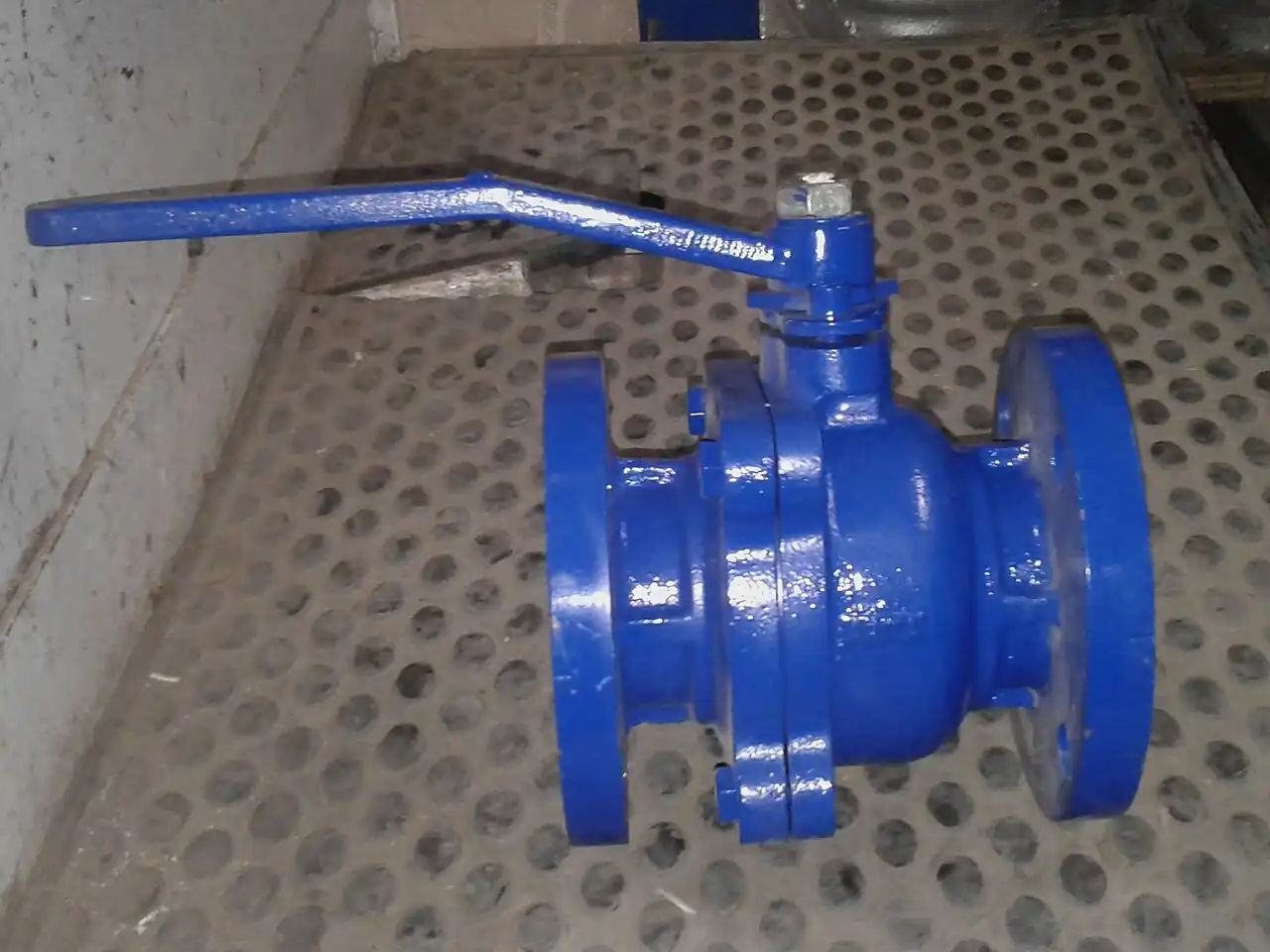
A v-port ball valve is a quarter-turn valve whose closure member is a ball with a V-shaped notch, a parabolic slot, or a machined segment of a ball, cut into its flow passage. Rotating the ball from closed toward open presents a triangular window that widens progressively instead of the sudden full-bore jump of a plain drilled ball, so stem position maps onto flow area in a controlled and repeatable way. The trim exists to combine three duties in one body: modulating control with a predictable characteristic, tight shutoff against line pressure, and a shearing ball edge that passes fibers and slurries which would hang up a globe plug. Sizes run from DN 15 to DN 600, classes CL150 to CL600, with rangeability claims from 100:1 to 300:1.
Procurement engineers meet these valves on paper machine stock dilution and consistency control lines at 2 to 5 percent consistency, on chemical and water dosing skids, on tank farm loading headers, and on water distribution pressure control stations where one valve must throttle across a wide turndown between day and night demand. The decision this page settles is narrow and practical: whether the loop should be served by a characterized ball instead of a classic globe trim, which notch angle and seat construction match the fluid, and what actuation and instrumentation pair with the body. The answer lands as an RFQ line set, size and notch angle and Cv and leakage class and seat material and actuator with fail action, and every chapter below feeds that line set so the control loop is bought, not hoped for.
This page treats the v-port ball valve as a purchasing object: what the characterized notch changes in real numbers, how ISA-75 sizing language maps onto datasheet rows, where soft seats end and hard coatings begin, and how notch angle, seat class, actuator, and fail action combine into a defensible RFQ. It is written for engineers who issue purchase specifications, not for readers who want a brochure summary.
Chapter 1 / 06
What a V-Port Ball Valve Is and What Is Being Decided
The closure member is the difference. A conventional ball valve built for isolation drills a straight cylindrical bore through the ball, so a 90 degree turn swings the line from fully open to fully shut with almost nothing useful in between: on a plain bore, roughly 70 percent of full flow arrives before the ball has rotated 30 degrees, and the loop spends its life on a cliff. A v-port ball valve replaces that bore with a notch or segment cut, so the same quarter turn exposes an opening that starts as a narrow triangular window and widens on a curve. The area versus rotation relationship is set by the geometry of the cut, which is exactly what the word characterized means when a datasheet uses it.
What is actually being decided in this purchase is whether one body can be trusted to do three jobs at once: modulate flow across a wide turndown with repeatable gain, shut off tightly enough to isolate equipment between batches, and pass the process fluid without packing solids into a seal pocket. The buyer commits to a characteristic curve, a seat construction, and an actuation package in the same purchase order. A valve chosen only on full-open Cv will control badly because the loop will live at the bottom of its travel; a valve chosen only on shutoff class will throttle badly because high recovery trim is not a cavitation instrument. The point of this page is that those outcomes can be checked on paper, at RFQ stage, in under an hour.
Against its neighbors, the characterized ball occupies deliberate ground, and the full comparison belongs in the selection chapter. The globe valve remains the reference modulating control valve, with plug trims that absorb high pressure drop and resist cavitation at rangeability ratios commonly near 50:1. The eccentric plug valve covers abrasive and hanging fluids with a rotary plug and a single seat. The butterfly valve wins large diameters on weight and cost but with modest rangeability and no shutoff credibility at high class. At the small end, a needle valve meters flows far below the smallest characterized ball Cv. The v-port ball valve takes the territory between them: quarter-turn compactness, a shearing notch edge that cuts fibers instead of collecting them, and enough rangeability for loops a plain trim cannot hold.
Four standards organize the datasheet. Sizing language comes from the ISA-75 series: ISA-75.01 defines the flow coefficient Cv, the liquid pressure recovery factor FL, and the pressure drop ratio Xt used in every sizing calculation, and ISA-75.02 defines how a manufacturer must test to certify those numbers. Design context for industrial ball valves comes from API 608, which fixes design, material, and test expectations for flanged and welded end bodies even though characterized control trims are usually manufacturer standards built on the same body architecture. Face-to-face dimensions follow ISO 5752 so a DN 50 valve from one maker fits the spool gap of another, and wall thickness with pressure temperature ratings follow ASME B16.34 by class. A datasheet that quotes none of these four is a price tag, not a specification.
The RFQ should also name the neighbors. A v-port station usually sits downstream of a process driver: after a centrifugal pump whose shutoff head, not nominal line pressure, sets the worst credible differential; after a check valve that exists to protect the pump rather than the valve; behind a Y strainer whose mesh is chosen to stop weld bead and scale during commissioning, when the seat is newest and most easily engraved. Line isolation for maintenance is normally a separate gate valve or a full-bore body, because a characterized trim is never the right instrument to blind a line with. Stating the whole station in the RFQ lets one supplier check gasket, flange drilling, and face-to-face compatibility across the package in a single pass instead of four arguments at delivery.
Chapter 2 / 06
How the Characterized Ball Shapes Flow
Mechanically the valve is simple. The ball sits between two seats and rotates 90 degrees through a stem. Closed, the intact land of the ball presses the downstream seat and shuts the notch off. As travel begins, the apex of the notch crosses the seat line and opens a triangular window whose width grows with rotation. At about 45 degrees the window is a trapezoid, and at 90 degrees the notch is fully exposed and the ball presents its maximum flow area. Because the notch edge sweeps across the seat with every stroke, strands, fibers, and soft solids are sheared and flushed rather than wedged into the sealing land, which is why paper stock, latex, and polymer slurries are natural services for this trim and immediate trouble for most plug cages.
The shape of the notch sets the inherent flow characteristic, the curve of flow versus travel at constant pressure drop. A narrow 30 degree notch spends the first half of travel opening a small and slowly growing window, so gain is low at low travel and rises steeply afterward, close to an equal percentage response, which is exactly what a loop wants when most of the circuit resistance lies elsewhere in the system. A 60 degree notch approximates a linear characteristic across the middle of travel and suits general flow duty. A 90 degree notch opens faster and reaches a higher full-open Cv, trading resolution at the bottom for capacity at the top. Specifying the notch angle is a control decision made against the process gain curve, not a mechanical detail copied from a catalog photograph.
Sizing follows ISA-75.01. In words: for liquids, volumetric flow equals the flow coefficient multiplied by the square root of pressure drop divided by relative density, with unit conventions fixed by the standard, and for gases the calculation adds an expansion factor built on Xt. The numbers that matter at RFQ stage: a DN 50 characterized ball typically carries a full-open Cv near 130, a DN 100 near 520, and a DN 200 near 1,900, with maker variation of roughly plus or minus 25 percent, so the quoted Cv table must be checked per size. Advertised rangeability of 100:1 to 300:1, with 200:1 typical of quality soft seated trims, means the minimum controllable Cv is that fraction of full Cv: a DN 50 valve at 200:1 still controls at Cv 0.65. That floor, not the full-open ceiling, is what beats a globe trim near 50:1 in wide turndown loops.
Torque decides the actuator. A quarter-turn characterized ball demands breakaway torque to shear the seat at the start of stroke, bearing and packing friction through travel, and hydrodynamic torque from flow acting on the notched ball, which peaks in the 20 to 50 degree band and can act with or against the motion depending on flow direction. Modulating duty therefore pairs the body with a pneumatic valve actuator sized on worst case torque plus a 1.25 to 1.5 safety factor, and with a valve positioner that closes the loop between controller signal and stem angle; without the positioner a modulating valve is an open loop guess that drifts with friction. An electric actuator with profile control suits slower loops and remote sites, and from about DN 300, or at high class with high differential, a scotch yoke actuator converts cylinder or motor torque into the quarter turn more efficiently than rack and pinion designs.
Cavitation is the failure mode that catches buyers migrating from globe trims. The characterized ball is a high recovery valve: static pressure falls far below the outlet pressure at the notch vena contracta and then recovers downstream, so a liquid can flash to vapor and collapse against the ball land and seat edge. Published FL values of 0.6 to 0.8, against roughly 0.85 to 0.9 for typical globe plugs, translate into hard service limits: on water with 10 bar drop taken in one stage, a single V-ball can sit deep in cavitation where a globe trim of the same Cv runs quiet. Gas service has the analogue in Xt and aerodynamic noise, which the same ISA-75 calculation checks. The remedies are structural: share the drop across two valves in series, accept a globe body for that station, or specify a low recovery trim where one is offered.
Chapter 3 / 06
Types, Construction, and Duty Boundaries
Three trim families cover most catalogs. The classic v-notch ball cuts a single V groove into a full ball, offered in 30, 60, and 90 degree included angles that set the characteristic as described in chapter 2. The parabolic characterized ball replaces the straight V with a curved window, machined so the area curve approximates a true equal percentage law more closely than any straight cut, at higher cost and usually in smaller sizes. The segmented ball uses a partial shell, typically a half or quarter ball segment carried on a shaft, pressing against a single seat. Within each family the buyer still chooses seat material, mounting architecture, and body material, and those three choices carry more warranty weight than the family name.
The segmented ball exists because a notched full ball grows heavy and expensive with diameter. A segment presses against one seat as it closes and cams clear of it within the first few degrees of opening, so seat wipe is short and wear spreads evenly along the seating face instead of concentrating at one land. Segmented trims dominate from DN 100 upward in control duty, reach class VI shutoff with soft seats, and adapt readily to high class and high temperature metal trims. The trade against a notched full ball is slightly coarser resolution at the bottom of travel, which matters only in loops that operate below 10 percent opening for long periods, and in those loops the parabolic or 30 degree notched trim is the better purchase anyway.
Seat construction sets the temperature and leakage envelope. Soft seats of PTFE or filled PTFE cover minus 29 to 200 deg C, hold FCI 70-2 class VI shutoff, and suit most water, chemical, and stock duties; PEEK seats extend to about 250 deg C and resist notch edge cutting in abrasive service. A metal seated ball valve, with tungsten carbide or chromium carbide coatings on both sealing faces, runs to 400 deg C and beyond in steam and hot oil, survives millions of cycles, and seats by a hard wiping contact instead of an elastomer squeeze; its leakage acceptance drops to class IV or class V with defined allowable rates, which must be accepted in the specification rather than discovered at factory test. The seat line on the datasheet is therefore two decisions at once, temperature limit and leakage limit, and a weak answer on either one is a reject flag on the quotation.
Mounting and materials follow the rest of the ball valve family. A floating ball valve, in which the ball is free to float onto the downstream seat under line pressure, is economical and standard through about DN 150 and CL300. A trunnion ball valve, with the ball held on fixed trunnion bearings and seat rings spring loaded against it, carries the hydraulic load at larger sizes and higher classes and gives more repeatable seating behavior, which matters when the loop counts on the low end of the rangeability claim. Shafts and stems are 17-4 PH or 420 stainless in standard builds; bodies are WCB carbon steel for utility duty, CF8M stainless steel for chemical and clean service, and duplex 2205 for high chloride fluids. The stainless steel body premium runs 60 to 100 percent over carbon steel at DN 50, and it buys corrosion margin on the seat land that no coating restores once the notch edge begins to cut.
Boundaries are worth stating bluntly. This valve is not a safety device and never substitutes for a safety relief valve on any line. It is not the right instrument below about Cv 1, where a needle valve or a small globe trim meters with far better resolution. It should not take a full liquid letdown drop in one stage at high differential, for the cavitation reasons in chapter 2. And if the duty is two-position switching with occasional stroke, a plain full-bore body at a third of the price is the honest purchase: the characterized notch earns its premium only when the loop lives inside the throttling band for hours at a time.
The duty map below consolidates the boundaries into one table a specifier can scan before writing the RFQ; it pairs common services with the construction that survives them and the construction that generates callbacks.
Service
Suitable construction
Construction to avoid
Paper stock dilution, 2 to 5 percent consistency
60 deg notch, soft seat, CF8M or duplex trim
Globe plug trim without cage relief (fibers wrap the plug)
Water distribution pressure control, DN 100 to DN 300
Segmented ball, PTFE seat, actuated with positioner
90 deg notch where night flow sits below 20 percent travel
Chemical dosing with wide turndown
30 deg or parabolic notch, PTFE seat, CF8M body
Metal seat where class VI shutoff is required between doses
Saturated steam distribution near 180 deg C
PEEK seat or metal seated trim, class IV accepted
Standard PTFE seat (creeps at sustained high temperature)
Hot oil and thermal fluid to 350 deg C
Metal seated ball valve with carbide coatings
Any soft seat construction
Abrasive mineral slurry
Metal seated trim with coated segment and flush seals
Soft seat notch (seat edge cuts within weeks)
High drop liquid letdown, single stage
Not this valve; stage two valves or use a globe trim
Any characterized ball alone at 8 bar or more drop
Two-position isolation with rare stroke
Plain full-bore ball valve
V-notch premium spent on a duty that never throttles
Chapter 4 / 06
Key Specification Parameters
The table below decodes the datasheet lines that decide whether a quoted valve matches the service. Each row is a purchase defining parameter; the paragraphs after the table explain what to demand and what a weak answer looks like.
Attribute
Typical range or options
What it decides
Nominal size
DN 15 to DN 600, control volume DN 25 to DN 300
Pipe schedule, flange drilling, face-to-face, and actuator torque class
Pressure class
CL150, CL300, CL600; PN16 to PN63 equivalents
Body rating per ASME B16.34 and the seat derate applied at temperature
Full-open loss and where normal duty lands on the travel curve
Notch or trim geometry
30, 60, 90 deg V-notch; parabolic; segmented
Inherent characteristic and loop gain through the throttling band
Rangeability
100:1 floor, 200:1 typical, 300:1 premium trims
Minimum controllable Cv and turndown coverage of the loop
Leakage class
FCI 70-2 class VI soft seat; class IV or V metal seat
Acceptance test applied at the seat during factory test
Seat and temperature
PTFE minus 29 to 200 deg C; PEEK to 250; carbide metal to 400 plus
Seat compound, derate curve, and shutoff credibility at heat
Body, ball, stem materials
WCB, CF8M, duplex 2205; ball and coating; 17-4 PH stem
Corrosion envelope, code acceptance, and stem strength
Mounting architecture
Floating ball valve to about DN 150; trunnion ball valve above
Seating repeatability, size ceiling, and maintenance access
FL and Xt per ISA-75
FL 0.6 to 0.8; Xt 0.55 to 0.75 published
Cavitation and noise check before the valve is bought, not after
The Cv row deserves a paragraph of its own because it is the row most often misused. Manufacturers publish full-open Cv because it flatters the valve, but a modulating selection is made at the operating point: demand the Cv versus travel table at fixed steps, 10, 20, 30 through 90 degrees or the percentage equivalents, and verify that normal flow falls between 20 and 70 percent travel. An oversized characterized ball behaves like a quick opening valve with a resolution problem, and no positioner tuning recovers what the size choice destroyed. The companion number is the minimum controllable Cv implied by the rangeability claim, which must sit below the minimum process flow with margin, or the loop will spend every night cycling against a valve that cannot resolve small moves.
The FL and Xt row is the cavitation and noise gate. These factors are not decoration: the ISA-75.01 calculation uses FL to compare the allowable pressure drop at the service temperature against the required drop, and a quotation without published FL at travel is silent exactly where the risk lives. Ask for FL at the expected travel band, not the single catalog value, because recovery behavior changes as the notch opens. The characterization table below compresses the trim geometry decision into the form a control engineer can argue from in a specification meeting.
Trim geometry
Inherent behavior
Where it earns its cost
30 degree V-notch
Steep, near equal percentage, finest low travel resolution
Level, pressure, and dosing loops with wide turndown
60 degree V-notch
Near linear across the middle travel band
General flow control, blending, stock dilution
90 degree V-notch
Fast opening, highest full-open Cv of the V family
Fill and dump duty with limited low flow demand
Parabolic characterized window
Closest to a true equal percentage law
Temperature loops on exchangers where loop gain must stay flat
Segmented ball
Linear to modified equal percentage
DN 100 and larger modulating stations and high class service
The actuation rows close the specification. A modulating valve is bought as a package: body, pneumatic valve actuator or electric actuator sized on breakaway torque at maximum credible differential with the 1.25 to 1.5 factor, a valve positioner matched to the signal and to the failure strategy, and limit or position feedback where operations audits the loop. At DN 300 and above, a scotch yoke actuator is usually the efficient torque path, and ISO 5210 or ISO 5211 mounting on the stem nut keeps the package interchangeable when the actuator is replaced years later. The quotation that quotes the body and leaves actuation as an exercise is not a complete quotation.
Chapter 5 / 06
Selection Decision Factors and RFQ Language
The decision sequence is short enough to run as a checklist in a specification meeting, and each step eliminates a class of quotations before price comparisons begin.
Confirm the duty is genuinely modulating: if the valve switches rather than throttles, buy a plain ball valve and stop reading.
Define the fluid honestly, including fibers, crystals, and solids: consistency percentages and particle sizes decide seat and coating, not brochure chemistry.
Compute the maximum credible differential, including pump shutoff head, and run the ISA-75.01 cavitation check with the quoted FL before, not after, selection.
Set the temperature envelope with cleaning and sterilization cycles if any, then pick the seat: PTFE, filled PTFE, PEEK, or a carbide faced metal seated ball valve.
Choose notch or trim geometry against the process gain, using the characterization table in chapter 4, and write the chosen geometry into the RFQ by name.
Size on the operating point: full-open Cv plus the Cv versus travel table, with normal flow landing between 20 and 70 percent travel.
Package the actuation: actuator sized on worst case torque with safety factor, valve positioner matched to the control signal, fail action stated, feedback listed.
Fix the verification evidence: capacity test basis, seat leakage test, FL and Xt data, temperature derate table, and material certificates.
Against neighboring valve types, the comparison a specifier actually needs runs as follows, and it belongs here in the selection chapter rather than in the page title. The globe valve wins where the drop is high and cavitation or noise must be absorbed by trim design, and it still meters the smallest flows. The butterfly valve wins on installed cost and weight from about DN 400 in water service where rangeability demands are modest. The eccentric plug valve wins on hanging and abrasive fluids where its single seat and rotary wipe outperform cages. The v-port ball valve wins when the loop needs the combination: rangeability near 200:1, class VI or class V shutoff, and a shearing edge that keeps the seat clean in fibrous stock that would wrap a globe plug within a shift. Choose the combination the loop needs, not the type a supplier has on promotion.
The application map below turns that comparison into a table the project file can carry.
Application
Construction to specify
Check before order
Stock consistency and dilution control
60 deg notch or segmented trim, PEEK or filled PTFE seat, flush ports
Seat resiliency at fiber load; breakaway torque with loaded seat
Centrifugal pump minimum flow recirculation
Multistage or staged drop; characterized ball only with downstream orifice share
Cavitation check at shutoff head, not nominal head
Water district pressure control
Segmented ball DN 100 to DN 300, positioner, sealed stem per ISO 15848 where audits apply
Night flow minimum against rangeability floor
Chemical dosing wide turndown
30 deg or parabolic notch, PTFE seat, CF8M body and trim
Minimum controllable Cv against smallest dose; class VI between doses
Steam and hot oil isolation with modulating startup
Metal seated trim with carbide coating, class IV accepted in writing
Leakage acceptance and thermal cycling derate table
Tank farm loading header
Segmented trim, dual block arrangement for meter proving
Face-to-face per ISO 5752 against existing spools
The RFQ block should be written once and reused. A complete block reads: quantity, size, and class; trim geometry by name with notch angle; required Cv at maximum and normal flow with the operating point stated; rangeability requirement with the minimum controllable Cv; leakage class and test basis; fluid with solids and fiber loading; minimum and maximum temperature with cycles; maximum steady and transient differential; seat, body, ball, coating, and stem materials; actuator type, fail action, positioner signal type, and feedback accessories; face-to-face per ISO 5752 and end details, flange drilling included; certificates required, typically capacity test to ISA-75.02, seat test to FCI 70-2, material certificates EN 10204 3.1, and fugitive emission qualification where the site audits it; and the drawing package expectation, Cv versus travel, torque curve, FL and Xt, and the pressure temperature derate table. A quotation returned without the Cv table or the FL data is incomplete at any price.
Chapter 6 / 06
Installation, Standards, Failure Modes, and Maintenance
Installation quality decides whether the trim reaches its catalog life. Mount the body with the stem horizontal and, where the choice exists, avoid arrangements that pack solids into the lower seat cavity, because gravity settles fiber into whichever land faces down in vertical lines. Give the valve the same straight run respect as any control element, about 5 pipe diameters upstream clear of elbows and pumps, not because the ball needs flow conditioning but because the process flow measurement used to tune the loop does. Flange bolts are brought up in a cross pattern to the supplier torque table; an over-torched joint on a soft seated ball distorts the seat ring and creates the leak that gets blamed on the trim. Actuator mounting follows ISO 5210 or 5211 dimensions, and the positioner is mounted and calibrated with the valve wet, in the line, at working pressure.
Commissioning practice protects two things: the seat and the loop. Flush the line before first stroke, because the first closure of a notched ball against weld spatter engraves the seat land for the rest of its life, and a commissioning strainer is cheaper than a seat. Stroke the valve across full travel with the positioner in manual and record the actual 0 and 100 percent points, the deadband, and the hysteresis; a characterized ball with more than 2 to 3 percent hysteresis has a packing or positioner problem that tuning will not hide. Verify the fail action by bleeding the air, not by trusting the nameplate. On loops that matter, capture a short stroke test at three signal points and file it as the baseline for condition monitoring.
The standards set the verification frame. ISA-75.01 and ISA-75.02 fix the sizing equations and the capacity test method behind every Cv and FL figure. API 608 provides the ball valve design context. ISO 5752 fixes face-to-face interchange. ASME B16.34 governs wall and pressure temperature by class. FCI 70-2 defines the seat leakage classes quoted on the test certificate. Where the service carries fire risk, API 607 or ISO 10497 qualification must be demanded explicitly, because a standard soft seated body carries none. Where the site audits fugitive emissions, ISO 15848 stem testing replaces the default packing acceptance. A specification that cites the standards by name in the RFQ block transfers the burden of proof to the supplier, which is where it belongs.
Failure modes in service follow a short and predictable list. Seat engraving and edge cutting: fibers or crystals cut the notch edge or the seat land, leakage rises first at low differential, and the Cv versus travel curve drifts so the loop slowly retunes itself around a damaged instrument; the fix is seat or coated trim replacement, planned at the first drift signal rather than at failure. Bearing and trunnion wear: stem play appears, hysteresis grows, and on trunnion designs the seat load relaxes; detected by the annual stroke test. Packing leakage: adjust or replace, and if the service is hot or audited, upgrade to the low emission packing set. Cavitation damage: pitting on the ball land downstream of the notch, audible as gravel in the pipe, remedied by staging the drop or moving the duty to a globe trim. Actuator and positioner faults: stalls from undersizing after a seat ages and breakaway torque rises, and hunting from a positioner tuned for a friction level the valve no longer has.
Maintenance intervals scale with duty severity. A stock or slurry service deserves a stroke and hysteresis check quarterly and a seat inspection at every planned shutdown, with seats treated as consumables in the spares budget from day one. Clean water modulating duty stretches the same checks to annual, plus packing adjustment and a torque trend where the actuator reports it. Every valve that throttles continuously earns an internal inspection at the first major shutdown after three years regardless of apparent health, because a drifting characteristic curve is invisible from outside the loop until it is not. None of these checks costs a tenth of one unplanned line stop, and every one of them produces a number the next RFQ can use, which is how a purchasing file gets smarter instead of just older.
FAQ
What notch angle should I specify for a wide turndown loop?
Choose the notch angle against the loop, not the catalog cover. A 30 degree notch gives the finest resolution at small openings and behaves close to equal percentage, so it suits level, pressure, and dosing loops that spend long periods near closed. A 60 degree notch approximates linear over the middle travel band and fits general flow control. A 90 degree notch trades low travel resolution for maximum full-open Cv, appropriate where the valve mostly runs wide open with occasional deep throttling.
Can a v-port ball valve take a high pressure drop like a globe trim?
Not in one stage, usually. The characterized ball is a high recovery trim with published FL values of about 0.6 to 0.8, against roughly 0.85 to 0.9 for typical globe plugs, so it cavitates sooner on liquid letdown service. If the drop must be taken in one body, a globe trim or a staged multistage valve is the correct instrument. Two characterized balls in series, sharing the drop, are an acceptable workaround when fiber content rules out globe trims entirely.
What rangeability is realistic in practice?
Catalog claims run 100:1 to 300:1, with 200:1 typical of quality soft seated trims, and the honest comparison is with about 50:1 for a conventional globe trim. Two cautions apply: the claim is only as good as the seat, so a worn or fiber marked notch edge raises the controllable minimum, and an oversized valve wastes the rangeability because normal flow sits near the bottom of travel. Size so that normal duty lands between 20 and 70 percent opening.
Should I choose a soft seat or a metal seat at 180 deg C?
At 180 deg C a filled PTFE seat is at the top of its working envelope and will creep, so specify PEEK, rated to about 250 deg C, or a metal seated trim with carbide coatings rated to 400 deg C and beyond. Accept the leakage consequence in writing: soft seats hold class VI, effectively bubble tight, while metal seats test to class IV or class V with defined allowable rates. The temperature derate table belongs in the quotation, not in a later dispute.
How do I verify the Cv a supplier quotes?
Ask for Cv versus travel data at fixed travel steps, 10, 20, 30 through 90 degrees or equivalent percentages, plus the certified full-open Cv and the test basis, which is ISA-75.02 for capacity verification. A single full-open number cannot support a modulating selection. Check that the normal operating point falls between 20 and 70 percent travel and that the minimum controllable Cv, set by the quoted rangeability, is below your minimum process flow with margin.
Why does my loop oscillate at small openings?
Three usual causes. First, oversizing: if normal flow needs less than 10 percent travel, the loop lives on the steep part of the curve and the controller cannot hold it, and a smaller trim or a finer notch fixes it. Second, seat damage: a notch edge cut by fibers or crystals passes more flow at low travel than the characteristic predicts. Third, positioner condition: a valve positioner with excessive deadband or a worn feedback linkage adds oscillation of its own, independent of the trim.
What actuation should I pair with stock or slurry service?
Modulating stock duty pairs a pneumatic valve actuator with a valve positioner, sized on breakaway torque at maximum differential with a 1.25 to 1.5 safety factor, with spring return to the fail position that protects downstream dilution. Electric actuation suits remote skids and slower loops, but check duty cycle against stroke frequency. From DN 300 a scotch yoke actuator delivers the torque more efficiently. Specify limit switches and stem position feedback wherever the consistency loop is audited.