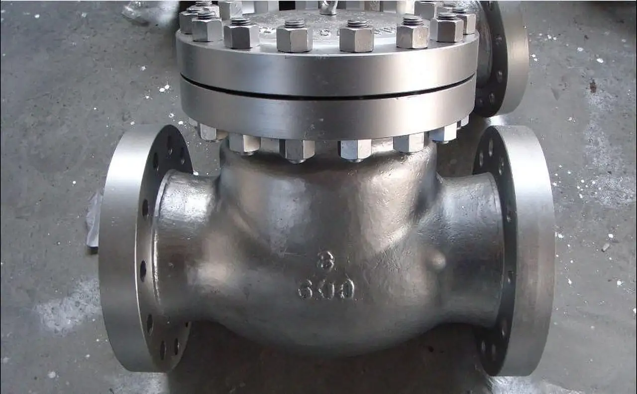
A tilting disc check valve is a line check valve whose disc swings on a pivot shaft set on an inclined axis: the disc plane is tilted, typically 15 to 30 degrees off the pipe axis, and the seat centerline sits raised toward the top of the body. Forward flow reaches the disc edge and splits into two jets, one passing over the top of the disc and one under the bottom, and the balanced pressure field lifts the disc through a short stroke of roughly 15 degrees of travel. Reverse flow arrives at that same inclined face and pushes the disc home onto its seat. Catalogs sell the architecture under several names, tilted disc and slanting disc among them, and the tilting disk spelling appears in older plant documents; this page uses one name and treats the others as synonyms. What the geometry buys is the point of the product: a short, low torque closure that seats the disc before reverse velocity can build, in a body whose flow passage is streamlined enough to run 30 to 50 percent less headloss than a plain swing valve of the same size.
Procurement engineers meet these valves where water moves in large quantity and slam is not tolerated: circulating water systems at power plants, municipal pumping station discharge headers, raw water intake lines, cooling tower basins, hydro plant penstocks and tailrace gates, and the long transmission mains where a pump trip sends a decelerating column back at the station. The decision this page settles is whether the duty earns this architecture over its cheaper neighbors, and then the four commitments that follow: size chosen on velocity windows rather than line size, disc and seat materials for the water chemistry, closure control from plain hinge through lever and counterweight to oil dashpot, and orientation rules that keep the inclined disc behaving. The answer lands as an RFQ line set, tested per MSS SP-61 and ISO 5208, and every chapter below feeds that line set so the station is bought, not hoped for.
This page treats the tilting disc check valve as a purchasing object: what the inclined seat changes in closure dynamics and headloss, how velocity windows and flutter limits set the size, which closure controls and materials survive circulating water and power duty, what MSS SP-61 and ISO 5208 evidence belongs on the certificate, and how all of it combines into a defensible RFQ. It is written for engineers who issue purchase specifications, not for readers who want a brochure summary.
Chapter 1 / 06
What a Tilting Disc Check Valve Is and What Is Being Decided
The closure member is the difference, and the word tilting describes it literally. In a plain swing check valve the disc hangs on a hinge pin whose axis is normal to flow, the disc swings through 60 to 90 degrees of travel, and the disc face meets its seat nearly head on, so the disc must chase the closing flow across a long arc. In the tilting disc check valve the pivot shaft sits on an axis inclined to the pipe, the disc plane tilted 15 to 30 degrees off the pipe axis with the seat centerline raised, and travel shrinks to roughly 15 degrees. Flow approaching the disc divides at the disc edge into two jets, above and below, so the hydrodynamic pressure centers close to the pivot instead of hanging out at the disc rim. The consequences are mechanical and they are measurable: closing torque stays low through the stroke, the disc covers a short distance to reach its seat, and the valve closes before reverse flow accelerates, which is what the word nonslam is doing in every catalog for this product.
Where the valve sits in the plant decides whether it is the right purchase. It is a water and cooling water animal first: circulating water systems at thermal power stations, municipal pumping discharge, raw water intake lines downstream of a vertical turbine pump or a bank of centrifugal pump sets, cooling tower basin feeds, hydro service, and the long pipelines where a pump trip drives a decelerating column back toward the station. In those services the two numbers that justify the premium are headloss and slam: the streamlined short stroke body carries roughly 30 to 50 percent lower flow resistance than a plain swing of the same size, which on a cooling water loop moving tens of thousands of cubic meters per hour converts directly into pump kilowatts, and the short travel closure suppresses the pressure spike that a long swing arc delivers when a column reverses.
Against its neighbors in the check valve family, the tilting disc occupies deliberate ground, and the full comparison belongs in the selection chapter. The plain swing check valve remains the cheaper default at smaller diameters and modest duty. The dual plate check valve, the wafer product built on the API 594 lineage, wins where the installation must be short and light between existing flanges. The axial flow check valve, a nozzle style spring assisted design, takes the slam critical and high velocity stations this page will hand over willingly. The piston check valve belongs on the pulsating discharge of reciprocating machines, not on water mains. The boundary that matters most in practice is the first one: below roughly DN 100, the economics favor simpler bodies, and above roughly DN 400 on water duty, the tilting disc and the butterfly style check families dominate the conversation, which is exactly where this product earns its place in a specification library.
What is actually being decided in this purchase is a set of four commitments. First, a size commitment made against velocity windows, not line schedule: the disc needs a sustained flow velocity, typically 1.5 to 2 m/s at normal flow, to open fully and run stably, and an oversized valve that never gets there wears its seat at partial opening. Second, a materials commitment: body, disc, seat ring, and shaft chosen against the water chemistry, from epoxy coated iron through WCB steel to CF8M, with discs in 316 or 17-4 PH stainless. Third, a closure control commitment: plain hinge, lever and counterweight, or oil dashpot, decided by the pump trip surge study. Fourth, an orientation commitment: the shaft runs horizontal, the flow arrow points the right way, and the maker's vertical line rules are read before the spool drawing is cut. A quotation that answers only the size has quoted a casting, not a check valve station.
Three standards organize the datasheet, with a fourth for context. MSS SP-61 governs the hydrostatic shell testing every cast steel valve must pass before shipment. ISO 5208 defines the seat leakage rates used when the closed disc is tested against pressure, and the rate achieved, not the word tight, belongs on the certificate. AWWA C508 governs wastewater check valve construction and appears in this family's world mostly as the reference a specifier will meet on adjacent projects; the tilting disc itself is a water and cooling product rather than a sewage product, and the notes chapter says why. AWWA C504, the butterfly valve standard, supplies the coating and waterworks context the larger bodies of this family are often built to. Face-to-face and flange drilling follow EN 1092 or ASME B16.1 and B16.5 by the yard standard, and the spool gap must be checked against the family drawing because this body is not face-to-face interchangeable with the plain swing it replaces. A datasheet that quotes none of these is a price tag, not a specification.
Chapter 2 / 06
How the Inclined Disc Moves and Closes
Walk the stroke from closed to full open. Closed, the inclined disc face sits in a seat ring machined into the body on the raised centerline, and line pressure on the upstream face presses the disc into that seat along a continuous circle. As forward flow builds, the stream divides at the disc edge into two jets, one over the top of the disc and one under the bottom, and because the seat centerline is raised, the lower jet acts on a larger projected area than the upper, producing a net opening moment about the pivot. The disc swings clear through roughly 15 degrees and rides in a stabilizing flow field: with the disc fully open, both jets recombine downstream and the disc sits in the wake of its own hinge line, close to parallel with the flow, which is why the full open body behaves more like a smooth bore than like a plug in the stream.
Closure is where the geometry pays. When the driving pumps trip or a downstream valve shuts, the column decelerates, forward flow falls toward zero, and the net opening moment disappears; the disc begins to swing home under its own weight, gravity component set by the disc plane inclination, assisted on some executions by a lever and counterweight or resisted and metered by a dashpot. Because travel is only about 15 degrees, the disc covers the distance in a fraction of the arc a plain swing must travel, and because the center of pressure of the decelerating flow acts near the pivot, the closing torque is low rather than rim loaded. The disc reaches its seat while reverse velocity is still small, so the kinetic energy the closure must arrest is modest, and the pressure spike downstream of the seating event stays in the range a water system tolerates. That is the whole nonslam argument in mechanics, and it is the reason the pump trip case, not the steady flow case, decides the closure control option on the RFQ.
Headloss is the second half of the argument, and it comes from the body, not just the disc. A plain swing body swings a long disc on a top hinge, so the disc sits midstream at a steep angle when open and the body needs a wide pocket to house the arc, and both cost resistance. The tilting disc body is a streamlined short stroke passage: the open disc lies close to the flow direction, the pocket is shallow, and the two jets merge over a smooth seat ring contour. Makers publish flow coefficients and pressure drop curves for this reason, and the honest specification statement is comparative: at equal size and equal duty velocity, the tilting disc runs roughly 30 to 50 percent lower resistance than the plain swing execution, worth several tenths of a meter of head on a circulating water loop and several kilowatts of pump power per valve per year. The selection chapter converts that into the velocity window language an RFQ can carry.
The velocity window is the sizing honesty of this product. The disc needs sustained velocity to open fully and to run stably in the open position: practice puts stable full open at typically 1.5 to 2 m/s at normal flow, and below about 10 percent of rated capacity flow the disc comes off its stabilizing field and flutters, oscillating through a small arc around the pivot. Flutter is not a curiosity; it hammers the disc pin and bushings, converts bearing clearance into play, and shows up a year later as a late closing disc and a slam that the valve was bought to prevent. The same window language separates this valve from the suction side of the station: a foot valve at the intake holds prime at rest and lives by its screen, while the discharge check lives by its velocity window, and confusing the two duties is how stations end up with the wrong hardware on both. Sizing the valve one or two line sizes down, so that normal duty sits inside the window, is standard practice on cooling water systems and long mains, and it is the reason the RFQ states normal, minimum, and maximum flow, not just the pipe diameter.
On pump trip, the valve and the water column negotiate. The deceleration of the column sets how fast reverse velocity would build if nothing closed; the disc travel time, set by geometry, counterweight, or dashpot, sets when the disc is home. On short loops the plain hinge closes fast enough. On long lines, high trip heads, or systems with elevation change, the column can reverse appreciably before even a short stroke disc seats, and the closure then arrests real reverse flow, which is where the oil dashpot earns its price: a dual speed dashpot lets the disc move freely for most of its travel so it is nearly home as flow crosses zero, then meters the last few degrees of travel through a cushioning orifice so the seating event itself cannot generate a spike. The closing characteristic curve, disc position versus time under stated conditions, is maker data, and the surge study that consumes it is part of the specification package on any line long enough to need it.
Two mechanism details close the chapter. The pivot shaft runs on bushings in the body, and the shaft centerline must sit horizontal in service so gravity holds the disc in a defined rest position against its stop; a shaft installed out of level lets the disc drift and changes the closure timing, which the installation chapter returns to with the orientation rules. And the seat ring is a replaceable part in this family: the disc seals on a ring that can be renewed in the line, which turns the most common long term failure, seat wear, into a maintenance event instead of a valve replacement, a lifecycle fact the purchasing file should reflect in the spares list.
Chapter 3 / 06
Types, Construction, and Duty Boundaries
The family sorts by closure control and by body architecture, and the combinations cover most catalogs. The standard water duty valve is a plain hinge, metal seated execution: a disc in 316 or 17-4 PH stainless seating on a bronze or 316 stainless seat ring, in a body of epoxy coated ductile iron, WCB steel, or CF8M, built for raw water, filtered water, circulating water, and municipal pumping. The lever and counterweight execution hangs an external lever on the shaft extension with adjustable weights: the counterweight biases the disc toward closure so it starts home earlier as flow decelerates, and it suits large horizontal water lines where the plain disc's gravity moment alone is not enough for the trip case. The oil dashpot execution replaces the lever effect with a hydraulic cylinder that meters the shaft: free travel through most of the arc, then a cushioned last few degrees, built for severe surge duty on long lines and high trip heads. On large vertical installations the external dashpot and counterweight hardware mounts alongside the shaft, because a vertical shaft changes the gravity moment the plain design assumes.
The power execution is a different body class and deserves its own line. Pressure seal bonnet constructions, in the class represented by the CRANE PACIFIC cast tilting disc lines, carry the architecture into steam feed and boiler feedwater service at pressure classes well above the water range, with alloy castings and pressure seal closures replacing the bolted bonnet of the water valve. The physics travels, short stroke, low torque, nonslam closure on feedwater lines where trip transients are expensive, but the materials, class, and test regime all move up with the service, and the waterworks pricing intuition does not follow. A buyer crossing from the water valve to the feedwater valve should treat it as a new specification, not a size change.
Ranges and materials in numbers: sizes run DN 50 to DN 2400 and beyond in the water families, with pressure classes PN10 and PN16 standard through PN40 in water duty and the pressure seal executions above that. Bodies are ductile iron with epoxy lining for potable and raw water, WCB cast steel for industrial cooling and fire water, and CF8M stainless for brackish and chemical bearing circuits. Discs run 316 stainless as the default and 17-4 PH where higher strength or harder seat faces are wanted; seat rings are bronze or 316 stainless, replaceable in the line; shafts are stainless in bushings designed for wash down. End connections are flanged to the yard drilling standard, with the flange pattern and facing checked against the family face-to-face drawing rather than assumed equal to the swing valve being replaced. On the very largest water lines, the isolation companion on the same header is usually a butterfly valve, while this valve handles the check duty.
The table below consolidates the styles into the form a specifier can scan before writing the RFQ.
Style
Closure control
What it buys
Typical duty
Standard water duty, plain hinge
Disc gravity moment on inclined axis, no add-ons
Short stroke nonslam closure at lowest cost in the family
Municipal pumping, raw and filtered water, general cooling loops
Lever and counterweight
Adjustable external weights bias the disc toward closure
Earlier closure start on decelerating flow, tunable on site
Large horizontal water lines, moderate trip heads
Oil dashpot controlled
Dual speed hydraulic cylinder on the shaft
Free travel to near seated, cushioned last degrees, no seating spike
Severe surge duty, long transmission mains, high trip heads
External dashpot, vertical execution
Dashpot and counterweight hardware beside a vertical shaft
Closure timing control where gravity acts across the disc
Large vertical lines, sump and cooling tower risers
Pressure seal power class
Lever or dashpot per maker, pressure seal bonnet body
Nonslam check duty at steam and feedwater classes
Boiler feedwater, steam feed lines, high class power service
Boundaries deserve plain statements, because this valve is regularly asked to do jobs that belong to neighbors. It is not a pulsation damper: the discharge of reciprocating pumps and compressors belongs to the piston check valve family, whose inline moving member rides each pulse. It is not the wafer space saver: where the spool between two existing flanges is a few centimeters, the dual plate check valve is the product the layout wants. It is not the terminal velocity specialist: very high velocity lines and slam critical installations are cleaner in an axial flow check valve, whose spring assisted nozzle member closes along the flow axis. And it is not a safety device of any kind; overpressure protection belongs to hardware built for it. Inside its own ground, water and cooling duty from DN 50 to DN 2400, with headloss and slam both on the specification agenda, it is the architecture the power and municipal industries keep returning to, and the next two chapters turn that into datasheet rows.
Chapter 4 / 06
Key Specification Parameters
The table below decodes the datasheet lines that decide whether a quoted valve matches the station. Each row is purchase defining; the paragraphs after the table explain what to demand and what a weak answer looks like.
Attribute
Typical range or options
What it decides
Nominal size
DN 50 to DN 2400 and larger; size on velocity, not line schedule
Whether normal flow sits inside the stable full open window
Pressure class
PN10 and PN16 standard through PN40 water duty; pressure seal classes above for power service
Shell rating and the flange class of the station spool
Water chemistry, coating system, and weight at large sizes
Disc
316 stainless default, 17-4 PH for harder duty
Seat face life and shaft strength margin
Seat ring
Bronze or 316 stainless, replaceable in line
Renewability of the sealing circle and leakage rate achieved
Closure control
Plain hinge, lever and counterweight, oil dashpot, external dashpot for vertical
Slam behavior on the pump trip case from the surge study
Headloss data
Flow coefficient and pressure drop curve at duty velocity, maker tables govern
Pump energy budget and the 30 to 50 percent advantage claim check
Velocity window
Stable full open at typically 1.5 to 2 m/s; flutter risk below about 10 percent of capacity flow
Sizing honesty, partial open wear, and disc stability
Tests and certificates
Shell per MSS SP-61, seat leakage per ISO 5208, material certificates EN 10204 3.1
The evidence set behind the quotation
The headloss row deserves its own paragraph because it is the row most often waved at with a single catalog number. Demand the pressure drop at the duty velocity, not at some reference condition: a valve quoted at a flow coefficient measured at 3 m/s tells a station running 1.8 m/s very little. Read the curve at normal flow, at minimum continuous flow, and at the maximum runout the pumps can deliver, and check that the minimum sits above the flutter threshold, roughly the 10 percent of capacity flow figure above, so the disc never lives in the oscillating band. The comparative claim, 30 to 50 percent lower resistance than a plain swing at equal size, is a family level statement; the purchase decision runs on the maker's own curve at the station's own three flows.
The closure control row is decided by the pump trip case, and the data that supports it is the closing characteristic. Ask for the disc position versus time curve under stated conditions, the dashpot oil grade and fill procedure if a dashpot is quoted, and the counterweight setting range if a lever is quoted. A surge study on a long line or a high head station consumes that curve and returns the answer: plain hinge closes fast enough, or a lever buys margin, or only a dashpot keeps the reverse flow spike inside the pipe rating. The study fee is small against the cost of a slammed main, and the specification should name it as the basis of the closure choice rather than leaving the option to the supplier's default.
The closure options table compresses the decision into the form a specification meeting can argue from.
Closure option
Mechanism
Where it earns its cost
Plain inclined hinge
Short stroke disc, gravity moment on the tilted axis, no add-ons
Most water and cooling duty with modest trip heads and short lines
Lever and counterweight
Adjustable external weight starts the disc home early in deceleration
Large horizontal mains where early closure start is worth tuning
Dual speed oil dashpot
Free travel to near seated, metered cushion over the last degrees
Severe surge duty, long transmission lines, high trip heads
External dashpot, vertical line kit
Dashpot and counterweight hardware for vertical shaft installs
Cooling tower risers, sump discharge, vertical lines per maker rules
What the datasheet must state, beyond the tables, is the evidence chain. Shell testing per MSS SP-61, hydrostatic at the class pressure, and a seat leakage test per ISO 5208 with the achieved rate written down, because a metal seated check valve has a defined allowable rate, not a promise of zero. Material certificates to EN 10204 3.1 on steel and stainless bodies, coating thickness and holidays testing where epoxy lining is quoted, and the face-to-face family drawing with flange drilling and facing stated against the yard standard. The joint to the station spool carries a gasket grade rated for the water chemistry and temperature, and the flange bolt torque table belongs in the installation chapter of the submittal rather than in the erector's memory. Stations that add a bypass or test tap usually hang it on a small globe valve, and the drawing should show it if operations wants one.
One honesty note closes the chapter, on leakage. A metal disc on a metal seat ring is a defined leakage product: the ISO 5208 rate on the certificate is the number the closed valve will deliver when new, and wear moves it in one direction only. Water systems tolerate this well, because the function is surge and reverse rotation protection, not drop tight isolation, and the isolation duty on the same header belongs to a gate valve or a butterfly valve sized for it. Specifiers who need tight closure between the check and something expensive downstream should say so in the RFQ and let the supplier answer with seat design and test rate, rather than discovering the rate after the pump starts recycling through the valve.
Chapter 5 / 06
Selection Decision Factors and RFQ Language
The decision sequence is short enough to run as a checklist in a specification meeting, and each step eliminates a class of quotations before price comparison starts.
Write the flow set honestly: normal, minimum continuous, and maximum runout, in m3/h and converted to velocity at the candidate size. If the minimum sits near the flutter floor, the valve is already the wrong size.
Size on the velocity window: pick the size that puts normal flow at 1.5 to 2 m/s so the disc runs fully open and stable, accepting a valve smaller than the line with reducers before judging any price.
Run the pump trip case: line length, elevation, and deceleration set whether plain closure suffices or the lever, counterweight, or dashpot option is required, with the maker closing characteristic as input.
Match materials to the water: epoxy iron for potable and raw, WCB steel for industrial cooling and fire water, CF8M for brackish and chemical duty; disc 316 or 17-4 PH, seat ring bronze or 316.
Fix the orientation: horizontal line preferred, shaft horizontal, flow arrow correct, and the maker's vertical line rules read before the layout is frozen.
Fix the evidence: shell test per MSS SP-61, seat leakage per ISO 5208 with the rate stated, material certificates, coating schedule, and the headloss curve at the three flows.
State the station: isolation gate valve beside the check, strainer hardware upstream where debris is real, and the supports that keep pipe load off the body.
Against the neighboring architectures, the honest comparison runs as follows, and it belongs here in the selection chapter. The swing check valve is cheaper at smaller diameters and its long swing arc is acceptable where headloss budgets are loose and trip heads are low; it stops being the economical answer when the energy lost across it, year over year, exceeds the premium of this family. The dual plate check valve, built on the API 594 wafer lineage, wins the short spool and the low weight class between existing flanges, and it is a fine neighbor; it does not match the headloss of this body at the largest water sizes, and its spring plates are a different maintenance conversation. The axial flow check valve takes the stations this page hands over willingly: very high velocity lines and slam critical installations where the spring assisted nozzle member closes along the flow axis with the least possible travel of all. The piston check valve owns the reciprocating discharge, where its member rides each pulse. On pump suction and wet well duty the check belongs to a foot valve at the intake, a different product with a screen. Choose the architecture the station's flow set and trip case demand, not the type a supplier has on promotion.
Selection is where the sizing honesty earns its keep, so it deserves its own paragraph. An oversized tilting disc runs with its disc partially open, seated nowhere near the stable field, wearing the seat ring at the contact band and flirting with the flutter threshold every time demand drops; the same valve one size down, with concentric reducers, runs fully open, quieter, and lives longer. The energy statement is the other half: every meter of head the valve does not lose is pump power not bought, and on a circulating water loop with several valves in series the family's 30 to 50 percent resistance advantage compounds into a measurable operating cost difference inside the first year. Both facts argue the same direction: buy the size the velocity window wants, and defend it in the specification narrative.
The station around the valve belongs in the RFQ. Isolation beside the check is a gate valve at most sizes or a butterfly valve on the largest mains, so the check can be serviced under a defined boundary; on buried water and wastewater adjacency the isolation often chosen is a knife gate valve, and on small taps a ball valve does the same work. Debris protection upstream, a Y strainer on smaller lines or a basket strainer on intake duty, keeps weld bead and shell out of the seat ring during commissioning, which is when the seat is newest and most engraveable. Station piping that includes an expansion joint should show it on the drawing, because the check valve is not a pipe support and never absorbs alignment error. At intake stations the pumping hardware names itself: a vertical turbine pump in the wet well or a centrifugal pump set on the deck, and the check sits on the discharge header of either.
The application map below turns the rules into a table the project file can carry.
Application
Construction to specify
Check before order
Municipal pumping station discharge
Water duty body, plain hinge or lever per trip case, isolation gate valve beside
Velocity window at normal and minimum flow; 5 diameters straight run upstream
Power plant circulating water
DN 600 to DN 2400, WCB or epoxy iron, lever or dashpot per surge study
Headloss curve at duty flow; closing characteristic matched to column deceleration
Cooling tower basin and risers
Water duty body, external dashpot kit where the line runs vertical
Maker vertical line rules; scaling maintenance access
Raw water intake station
Body per water chemistry, CF8M where brackish; basket strainer upstream
Debris load on seat ring; intake screen condition
Long transmission main, high trip head
Oil dashpot execution, sized with the surge model
Closing time against reverse flow build; cushion orifice setting
Boiler feedwater and steam feed
Pressure seal cast execution, power class materials
Class and test regime move up with service; ISO 5208 rate stated
Vertical turbine pump wet well header
Discharge check with horizontal shaft orientation confirmed
Shaft level tolerance; disc drift behavior at rest
The RFQ block should be written once and reused. A complete block reads: quantity, size, and class, with the size chosen on the velocity window and stated as such; the flow set, normal, minimum continuous, and maximum runout, with velocities at the chosen size; body, disc, seat ring, shaft, and bushing materials with coating schedule and EN 10204 3.1 certificates; closure control by name, plain hinge, lever and counterweight with setting range, or dual speed oil dashpot with oil grade, together with the closing characteristic curve; headloss data, flow coefficient and pressure drop at the three flows; tests, shell per MSS SP-61 and seat leakage per ISO 5208 with the achieved rate; orientation, horizontal line, shaft horizontal, flow arrow, and the vertical line execution where a riser applies; end details, flange drilling and facing against the family face-to-face drawing, with the gasket grade named; the station statement, isolation valve type beside the check, strainer hardware where debris is real, and supports that keep loads off the body; and the drawing package expectation, body sectional, seat ring renewal procedure, dashpot or lever detail, and torque table. A quotation returned without the headloss curve at the stated flows or the closing characteristic is incomplete at any price.
Chapter 6 / 06
Installation, Standards, Failure Modes, and Maintenance
Installation quality decides whether the closure dynamics the valve was bought for ever exist in the field. Set the body with the flow arrow in the flow direction, on horizontal lines where the layout allows, with the pivot shaft horizontal within the maker's tolerance, because an out of level shaft lets the disc drift off its rest position by gravity and changes the moment balance through the whole stroke. Give the valve about 5 pipe diameters of straight run upstream, clear of elbows and pumps, so the flow reaches the disc as a developed profile instead of a swirl, which is what the two jet balance assumes; an elbow discharging straight into the body loads one jet and unloads the other, and the disc runs crooked in service. Bring the flange bolts up in a cross pattern to the supplier torque table with the specified gasket, never an improvised one, and keep piping loads off the body: an expansion joint in the station exists to absorb movement, and the check valve exists to check, and neither may be asked to do the other's job. Stations with a test tap or bypass globe valve should have it installed with its small ball valve isolation and accessible now rather than retrofitted later by a crew with a porta-band saw, and buried stations whose line isolation is a knife gate valve get the extension stem and valve box located where a crew can actually reach it.
Commissioning protects two things: the seat ring and the record. Flush the line before first flow, because the first closure against weld spatter engraves the seat band for the life of the valve, and the commissioning period is when construction debris rides every pipe; where the station carries a commissioning Y strainer, clean it after the flush and record what it caught, because that debris history predicts the seat ring's first years better than any catalog note. Verify the disc moves: on a plain hinge, listen for the disc to lift as flow builds, and on a dashpot execution, confirm the oil charge and the free travel versus cushion behavior against the maker's procedure before the first trip test. Record the pump trip event at commissioning, pressure versus time if the site has the instrument for it, and file it as the baseline the maintenance trend starts from. A station that skips the trip test at commissioning discovers its surge behavior on the first real power blip instead, which is the most expensive way to learn it.
The standards set the verification frame. MSS SP-61 fixes the hydrostatic shell test the body must pass before shipment. ISO 5208 defines the seat leakage rate classes and the test method behind the closed disc figure on the certificate. AWWA C508, the wastewater check valve standard, is the neighbor context a specifier meets on adjacent projects, and this family is not its product: sewage and sludge duty runs in other check architectures built for solids, and a tilting disc specified there is a misuse. AWWA C504 supplies waterworks coating context on the larger iron bodies. Face-to-face and flange drilling follow the family drawing against EN 1092 or ASME standards by the yard. A specification that cites the standards by name in the RFQ block moves the burden of proof to the supplier, which is where it belongs.
Failure modes in service follow a short and predictable list. Seat ring wear and wire drawing: the sealing circle erodes a narrow channel, leakage back through the pump grows, and the station pays for recycled water it thought it was delivering; the cure is seat ring renewal, which this family designed for in-line service. Disc flutter at low flow: a station that runs below about 10 percent of capacity for long periods oscillates the disc, hammers the pin and bushings, and hands the plant a late closing, slamming valve a year later; the cure is operating practice or a correctly sized smaller valve, not a stronger pin. Pin and bushing wear: play at the pivot shows up first as slower closure, then as a slam the valve was bought to prevent, and a pin play measurement at every outage catches it before the slam does. Scaling in cooling water: carbonate and biofilm on the seat ring and disc edge change both the leakage rate and the closure balance, and an outage cleaning of the seat ring on a schedule set by the water chemistry keeps both in band; intake stations that run a basket strainer upstream should have its differential checked on the same schedule, because a blinded basket strainer pushes the station into exactly the low flow flutter band this chapter is warning about. Dashpot faults complete the list: lost or wrong oil, and a cushion orifice out of adjustment, each of which turns a controlled closure into an event; the dashpot service interval belongs on the same card as the rest.
Maintenance intervals scale with duty severity, and the tooling is a fitter with a torque wrench and a set of feeler gauges. At every planned outage on cooling water service, clean and inspect the seat ring, measure pin play against the maker limit, and exercise the disc through its stroke by hand with the isolation closed; on clean filtered water the same checks stretch to the multi year shutdown cycle. Renew seat rings on condition, and keep one ring set per critical station in the store, because the replaceable ring is the lifecycle promise this family sells and the spares list is where it is honored. Keep the commissioning trip record, the headloss curve, the closing characteristic, and the outage measurements in one file per station; the next RFQ is written from that file, and a specification that restates measured seat life, pin wear rates, and actual headloss converts supplier opinions into line items. That is how a purchasing file gets smarter instead of just older.
FAQ
How does a tilting disc check valve differ from a plain swing check valve?
The disc is the difference. A tilting disc seats on an inclined axis, with the disc plane tilted 15 to 30 degrees off the pipe axis and the seat centerline raised, so flow splits into two jets above and below the disc and travel shrinks to roughly 15 degrees. A plain swing hangs a disc on a top hinge through a much longer arc. The tilting disc therefore runs roughly 30 to 50 percent less headloss at equal size and closes with far less slam, at a higher purchase price.
What flow velocity keeps the disc fully open and stable?
Plan on 1.5 to 2 m/s sustained at normal flow for stable full open operation, and check that minimum continuous flow stays comfortably above roughly 10 percent of capacity, where the disc starts to flutter. Flutter hammers the pin and bushings and returns later as a slamming valve. Size on the velocity window, not the line schedule: a valve one size down with reducers, running fully open, outlasts an oversized valve that lives partially open and wears its seat in one band.
What does the oil dashpot actually do?
A dual speed dashpot lets the disc travel freely through most of its stroke so it is nearly seated as forward flow crosses zero, then meters the last few degrees through a cushioning orifice so the seating event itself generates no pressure spike. It is the closure control for severe surge duty: long lines, high trip heads, and installations where the decelerating water column would otherwise build appreciable reverse velocity. The closing characteristic curve is the maker data the surge study consumes.
Can these valves be installed on vertical flow lines?
Some executions can, under maker specific rules, and the RFQ must say so before the layout is frozen. The pivot shaft must run horizontal regardless, so the disc holds a defined rest position against gravity drift, and vertical shaft or vertical flow installs usually require the external dashpot and counterweight kit built for that duty. Horizontal lines remain the preferred installation, and the maker drawing, not a general rule, governs each case.
Why does the valve slam after a pump trip?
Look for four causes. Pin and bushing wear has introduced play, so the disc starts its closure late; a dashpot has lost oil or carries the wrong grade, so the cushion is gone; the valve is oversized and the disc lives partially open with flutter damage; or debris is holding the disc off its seat. The commissioning trip record and the outage pin play measurement separate the causes in minutes, and the fix follows the cause: renew the pin, service the dashpot, resize the valve, or clean the seat.
What testing and leakage classes apply to this valve?
The shell is hydrostatically tested per MSS SP-61 at the class pressure before shipment, and the closed disc is seat tested per ISO 5208 with the achieved leakage rate written on the certificate. A metal disc on a metal seat ring is a defined leakage product, not a drop tight one, which water and cooling systems tolerate because the function is surge and reverse rotation protection. Tight isolation on the same header belongs to the gate valve or butterfly valve installed beside the check.
What wears out first and how is it serviced?
The seat ring wears first, as wire drawing cuts a narrow leak channel over years of service, followed by the pivot pin and bushings as flutter and cycles introduce play. Both are designed services: the seat ring renews in the line without removing the body, and the pin assembly is replaced at the maker's play limit. On cooling water, add scale cleaning of the seat ring on a schedule set by the water chemistry, and keep one seat ring set per critical station in the spares store.