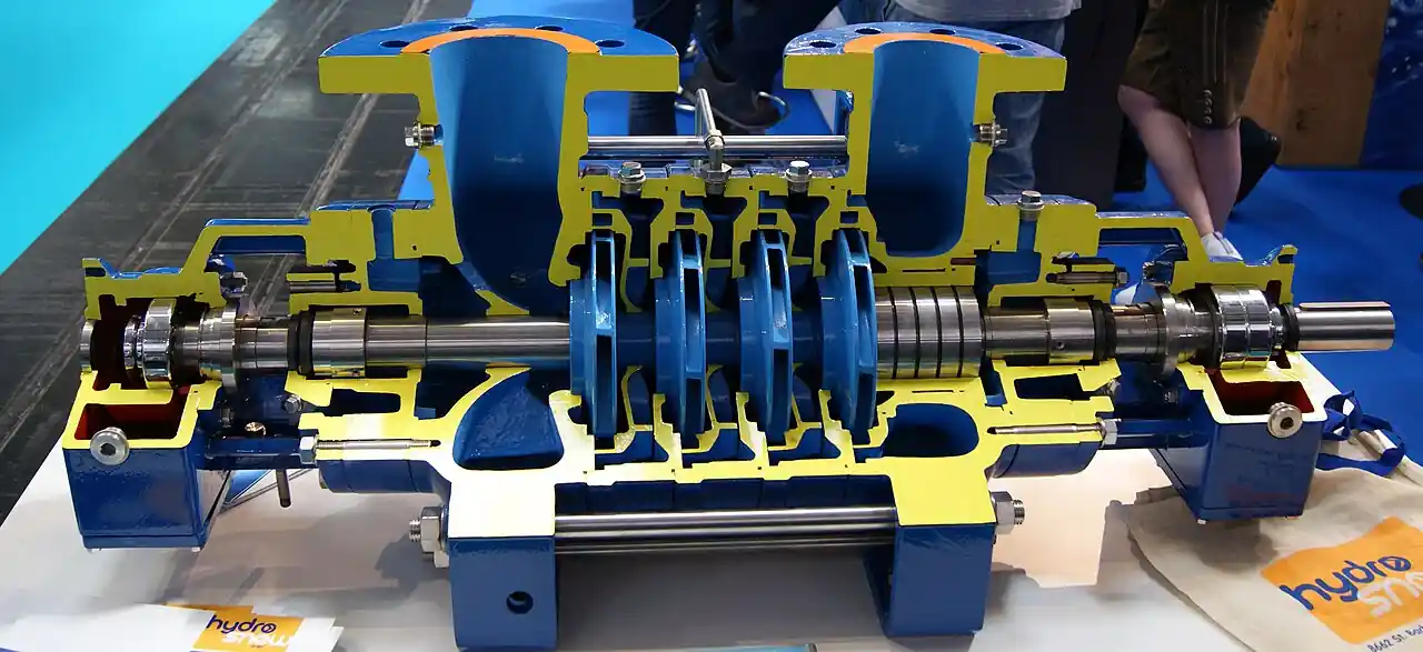
A vertical turbine pump is a rotodynamic machine in which one or more impeller and diffuser bowl stages, stacked in series inside a bowl assembly, sit at the bottom of a column pipe suspended from a surface discharge head. Liquid enters through a suction bell or screen, gains head stage by stage as it rises, and leaves through the discharge head into surface piping. The driver, a vertical solid shaft electric motor or a right angle gear drive, mounts on the discharge head, and torque reaches the bowls through a lineshaft running down the center of the column. The same architecture serves a 100 mm domestic well 60 m deep and a 1,000 mm municipal intake rated beyond 10,000 cubic metres per hour, which is why the machine is best understood as a vertical multistage pump built to be lowered into its own suction source.
Procurement engineers meet the vertical turbine pump, often called a lineshaft turbine pump or VTP, on well fields and municipal intakes, on cooling water and fire water systems, in mine dewatering shafts, and as inline boosters in a suction can on a pipeline. The decision this page settles is narrow and practical: which configuration fits the source, wet pit against can installation and lineshaft against submersible motor, how many stages at what setting deliver the duty, which materials survive the water chemistry, and which driver and lubrication choices keep the lineshaft stable. The answer lands as an RFQ line set, configuration, bowl size and stage count, setting depth, materials, driver, and intake conditions, and every chapter below feeds that line set so the hydraulics on paper survive contact with the water in the pit.
This page treats the vertical turbine pump as a purchasing object: how stacked bowls build head, why submergence rather than suction head sets the NPSH, what separates wet pit from can installations, which materials survive which water, and how the string is installed, protected, and maintained. It is written for engineers who issue purchase specifications for well, intake, and booster duty, not for readers who want a brochure summary.
Chapter 1 / 06
What a Vertical Turbine Pump Is and What Is Being Decided
Under Hydraulic Institute nomenclature, the vertical turbine pump is a vertically suspended centrifugal pump with its impellers enclosed in diffuser bowls. Each stage is an impeller throwing liquid outward into a stationary diffuser that converts velocity into pressure and redirects the flow upward into the next impeller eye, and the stages bolt together in a stack called the bowl assembly. Above the bowls comes the column pipe that carries the liquid to the surface, inside it the lineshaft that carries torque down to the impellers, and on top the discharge head, a casting or fabrication that supports the string, turns the flow horizontal, and carries the driver. Radial flow impellers suit higher head at lower flow, mixed flow impellers move large flows at modest head per stage, and specific speed is chosen against the duty.
What is actually being decided in this purchase is the configuration before the hydraulics. Wet pit against can installation decides whether the bowls hang in an open sump or well, or inside a sealed suction can piped into a pressurized line. Lineshaft against submersible motor decides whether the driver sits at the surface in air or close coupled beneath the bowls down the hole. Then come the numbers: bowl size and stage count at the measured setting depth, materials against the water analysis, lineshaft lubrication against the sand and temperature content of the water, and driver thrust capacity against the hydraulic downthrust at shutoff. A vertical turbine pump bought on flow and head alone is a machine with five unspecified decisions inside it, and each of them shows up later as a maintenance line item.
Against its neighbors the machine occupies deliberate ground, and the full tradeoff belongs in the selection chapter. A horizontal end suction centrifugal pump is limited on suction lift to roughly 7 to 8 m, needs priming on any open sump, and gives away staged head. A submersible pump puts its motor down the well close coupled to its own hydraulics and owns small and mid wells where no surface structure is wanted. A sewage pump with solids handling impellers owns raw wastewater, which a turbine bowl will not pass. A self priming pump solves small lift stations cheaply where the head is low and the depth is shallow. The vertical turbine pump takes the territory where the suction source is deep or the head must be built in many stages from a surface accessible driver: wells, intake sumps, wet pits, and pressurized can boosters.
Four standards organize the datasheet. The Hydraulic Institute vertical pump standards fix the nomenclature, the acceptance test basis, and, through the intake design standard, the sump geometry that makes the rated performance achievable in a real pit. API 610 defines the vertically suspended types used in refinery service, VS1 style lineshaft machines in wet pits and VS6 style double casing can machines on pressurized suction. NFPA 20 governs vertical turbine fire pumps, the listed machines, the suction conditions, and the test regime. ISO 9906 provides the hydraulic performance acceptance grades quoted on certified tests. A quotation that cites none of these standards is silent on exactly the points that decide whether the string runs to setting life or comes up early.
The RFQ should name the station, not the machine alone. A vertical turbine installation ships with a discharge head whose flange is drilled to match the plant piping class, isolation by a gate valve or, in large water works, a butterfly valve, a check valve on the discharge to keep the column from backspinning on trip, and an instrument set: a pressure transmitter or pressure gauge at the head, a level switch or level transmitter in the pit for start stop control, and where levels swing, a VFD with the PLC logic that trims speed to level or pressure. Writing the station into the purchase order lets one supplier check driver, head, valves, and controls against one duty point instead of discovering the mismatches at commissioning.
Chapter 2 / 06
How the Bowl Assembly Builds Head
Head is built by stacking. Each bowl stage develops its own head at the duty flow, and the total is the sum of the stages minus the friction losses in the column and discharge head. At two pole motor speeds, a mid range radial flow stage develops roughly 10 to 40 m of head, so a 150 m duty on a deep well lands at five to ten stages, and a low head cooling water duty may need one or two mixed flow stages at most. Vendor published bowl curves, head, efficiency, and power against flow for each stage count and trim, are the selection data, and bowl hydraulic efficiency runs typically 78 to 88 percent for good catalog ranges. The honest wire to water number must subtract lineshaft and thrust bearing losses, which grow with setting depth.
Submergence, not suction head, supplies the NPSH. There is no suction pipe standing above the impeller: the first stage sits in the water it draws, so NPSH available is set by the depth of the suction bell below the minimum water level, plus atmospheric pressure, minus vapor pressure and the entrance and screen losses. The same submergence must suppress free surface vortices, which form when the drawdown velocity at the surface is high enough to spin air into the suction bell. Hydraulic Institute intake design practice sizes the minimum submergence against the bowl inlet velocity and the sump geometry, and field practice for mid range flows commonly runs 1.5 to 3 m above the bell at the worst case low level, with more required for high specific speed bowls.
The lineshaft is the machine's spine and its weak link. Column sections, typically 3 m lengths, join at flanged or threaded couplings, and a bearing held in a spider at each joint supports the shaft. In open lineshaft construction the pumped water lubricates those bearings, typically rubber cutless styles, which is economical and self contained wherever the water is clean and cool. In enclosed lineshaft construction the shaft runs inside a center oil tube with bronze bearings, and a small oil drip or forced feed keeps grit and sand away from the bearing surfaces, which is the standard answer for sandy or moderately hot water. Shaft straightness limits are tight, because a bowed shaft whips in its bearings, and the lateral critical speed of the whole lineshaft must stay clear of the running speed at every stage count the vendor will trim to.
Thrust runs up the string to the surface. Each impeller generates hydraulic downthrust, worst at shutoff head, and the sum lands on the driver's thrust bearing, which is why vertical solid shaft motors for turbine duty carry thrust ratings orders of magnitude above horizontal machines of the same frame. The motor mounts on a P-base or C-face spigot on the discharge head; hollow shaft motors let the lineshaft pass through with an adjustable coupling or top nut that gives the lateral adjustment used to set impeller running clearances and to compensate for shaft stretch under load. Get the thrust number wrong and the failure arrives as a motor bearing failure that gets blamed on the motor maker instead of the pump selection.
Two field levers land the duty point on the curve. Stage count is chosen at order: more stages, more head at the same flow. Impeller trim machines the diameter down and moves the stage curve down and to the left, so a string that arrives overheaded is brought onto duty by trimming rather than by throttling, which wastes the energy the VFD was bought to save. Both levers should be quoted at order time with the resulting duty point against the certified curve, because a turbine left overheaded runs left of its best efficiency point, runs hot in its bearings, and eats its wear rings early.
Chapter 3 / 06
Types, Construction, and Duty Boundaries
The wet pit lineshaft machine is the base configuration. The bowl assembly hangs in an open well, sump, pond intake, or wet pit, drawing from a free surface, with the setting depth fixed by the drawdown between static and pumping levels plus the submergence margin. A screen or perforated suction bell keeps fish, leaves, and coarse debris out of the first stage. This is the configuration of municipal well fields, cooling water intakes, irrigation lift stations, and mine dewatering shafts, and it is the one the Hydraulic Institute intake design standard addresses directly: the sump, not the pump, is where rated head and flow are lost or preserved.
The can type machine replaces the sump with a sealed suction can bolted beneath the bowl assembly. Suction enters the can from a pressurized line, the bowls draw from the can volume, and the whole machine hangs inline in the piping like a vertical inline booster, which is why API 610 lists the double casing VS6 style for pressurized suction refinery service. The can converts NPSH from a submergence problem into a system pressure problem, saves the civil cost of a sump, and fits the machine into a plant plot space too small for any horizontal arrangement. The price is that the can adds a pressure boundary, nozzle loads land on the discharge head flange and the can suction flange, and the can diameter must be checked against the first stage flow pattern to avoid re ingesting recirculation.
The third family drops the lineshaft entirely. In submersible motor versions, close coupled motor bowls, the VIS class in the Goulds families named in the sources, the motor sits beneath or above the bowls down the hole and drives them directly, so there is no surface driver, no lineshaft losses, and no discharge head structure beyond a support elbow and the drop pipe. This configuration competes directly with the submersible pump families; the full comparison belongs in the selection chapter. For specification purposes the boundary is simple: the submersible motor version buys its compactness with a motor that lives in the pumped water, on the end of a power cable, pulled to service.
Materials follow the water analysis. Cast iron bowls with bronze impellers and stainless steel shafts remain the economical fresh water standard. All stainless steel construction, 316 class bowls, impellers, and shaft, answers brackish water, high chlorides, and corrosive groundwater, and duplex 2205 is the step up for seawater and aggressive chloride service. The lineshaft itself is commonly 416 or 316 stainless steel depending on chemistry, and the discharge head, which sees both the process and the atmosphere, is fabricated steel or cast iron with a stainless shaft sleeve running through the surface sealing, a packing box or a mechanical seal chosen against the water's abrasiveness.
The duty boundaries are worth stating bluntly. The machine wants water, not waste: rags and solids belong to a sewage pump family with the impellers to pass them, and a turbine bowl given that duty wraps or jams within days. Heavily abrasive mine water in large fractions of solids by weight belongs to a slurry pump or to a special alloy and rubber lined turbine negotiated with the vendor, not ordered from a catalog page. Air entrainment and vortexing from a poor sump starve the first stage regardless of materials. And the machine is not self priming in any sense, it is permanently flooded by design, so any application where the source can drain away from the suction bell needs a level interlock rather than a hope in the specification.
The duty map below consolidates the boundaries into one table a specifier can scan before writing the RFQ.
Service
Suitable construction
Construction to avoid
Municipal well field, 40 to 60 m setting
316 stainless steel bowls, water lubricated lineshaft, VFD
Blind stage count with no drawdown data
Cooling water intake from sump
Cast iron bowls, bronze impellers, screens to intake design practice
Submergence sized on average level, not minimum
Pipeline or plant booster in a can
VS6 style can machine, mechanical seal head, thrust checked at shutoff
Enclosed oil lubricated lineshaft, hard bearing materials
Open water lubricated lineshaft in grit
Irrigation lift from open pond
Mixed flow bowls, screened intake, right angle gear or motor drive
Radial flow bowls at high specific speed duty
Raw sewage lift
Not this machine; sewage pump family
Any turbine bowl given solids handling duty
Chapter 4 / 06
Key Specification Parameters
The table below decodes the datasheet lines that decide whether a quoted string matches the source and the duty; the paragraphs after it explain what to demand and what a weak answer looks like.
Attribute
Typical range or options
What it decides
Bowl size
About 100 to 1,000 mm outside diameter
Flow capacity per stage and fit inside the well casing or can
Vertical solid or hollow shaft motor, right angle gear
Thrust capacity, speed, and lateral adjustment
Discharge head
Flanged, commonly ANSI class 125 or 150, higher on cans
Piping loads, sealing, and driver mounting
Surface sealing
Packing box or mechanical seal
Leakage rate and maintenance access
The stage count row is where quotations go vague, so make it numeric against the source. A duty quoted as total head at surface must be decomposed: static lift from drawdown to discharge, friction in the column and head at duty flow, plus surface pressure where the string feeds a network. Dividing that total by the published stage head gives the stage count, and the count must be checked against the lateral critical speed limit of the lineshaft at that setting, not just against the curve. A quotation that omits the impeller trim is equally suspect, because trim shifts head and efficiency, and the certified curve should be the curve for the trim shipped.
The driver row carries the hidden failure. Hydraulic downthrust peaks at shutoff, so the motor thrust bearing must be sized for rotor weight plus shutoff thrust, not for the duty point value that looks smaller on the pump data sheet. Vertical solid shaft motors carry that thrust on a dedicated bearing and their frame size follows from it; hollow shaft motors accept the lineshaft through the top and give the lateral adjustment nut that sets impeller clearance and compensates stretch. Ask the vendor for the thrust curve of the string, not a single number, and state the driver voltage and start mode in the RFQ, because a deep well string that dips voltage on every start wears its motor insulation prematurely.
The configuration table below compresses the three families into the form a specifier can defend in a review meeting.
Configuration
Driver location
Suction source
Typical duty
Wet pit lineshaft, VS1 style
Surface, in air on the discharge head
Open sump, well, or pond intake
Well fields, intakes, mine dewatering
Can type, VS6 style
Surface, in air on the discharge head
Pressurized suction can inline
Pipeline and plant boosters, cold water NPSH relief
Submersible motor, VIS class
Down the hole, close coupled to the bowls
Direct, no suction geometry
Deep wells, small footprints, temporary systems
Name the configuration in the RFQ. The three families share hydraulics but not structure, spares, or failure modes, and a can type quotation against a wet pit specification is not a comparable line item, and a horizontal pipeline pump package is a third thing again. Where the source genuinely supports two configurations, state both in the RFQ and compare the quotations on setting depth limits, driver service, and pulling weight, which are the three costs that dominate the next ten years.
Chapter 5 / 06
Selection Decision Factors and RFQ Language
The decision sequence is short enough to run as a checklist in a specification meeting, and each step eliminates a class of quotations before price comparisons begin.
Fix the source first: static and pumping levels, drawdown, water chemistry including sand content, and sump or well geometry against intake design practice.
Compute submergence for NPSH and vortex control at the worst case low level, not the average level.
Decompose the duty: static lift, column friction, surface pressure, then stage count and impeller trim to land normal operation near the best efficiency point.
Choose materials from the water analysis: cast iron and bronze for clean fresh water, 316 stainless steel for brackish, duplex 2205 for seawater and high chloride.
Choose lineshaft lubrication: open and water lubricated for clean cool water, enclosed and oil lubricated for sandy or hot water, with the potable water constraint stated where it applies.
Size the driver for shutoff thrust and state voltage, start mode, and mounting, solid shaft, hollow shaft, or right angle gear.
Decide control: constant speed across a level band, or a VFD with a pressure transmitter or level input, PLC logic, and a level switch backup for start stop protection.
Fix verification: certified bowl curves at stated trim, acceptance to ISO 9906 or Hydraulic Institute grades, material certificates, and NFPA 20 listing where the duty is fire water.
Against the submersible motor version, the choice runs as follows, and it belongs here in the selection chapter. The lineshaft machine keeps its driver at the surface in air: any electrician can service it, the thrust bearing is accessible, and the motor can be a standard plant item in any enclosure and any hazardous area rating. It pays for that with lineshaft power losses, a critical speed limit on length, and a surface structure that must exist. The submersible motor version, the close coupled sibling that shares these hydraulics, drops the lineshaft and the structure, wins installed cost at deep settings, and puts the motor in the pumped water on the end of a power cable, so every motor fault means pulling the string. Deep wells with tight power or no surface structure favor submersible; plants that value surface access, driver interchangeability, and hazardous area flexibility favor lineshaft. Both are honest machines, and the dishonest selection is the one made without the pulling crane and the repair bay in the picture.
The horizontal alternatives own the flat ground. A can type vertical turbine pump as a booster competes with a horizontal multistage pump or a split case pipeline pump on footprint and NPSH: the can machine hangs inline, keeps its suction always flooded from system pressure, and needs no priming on hot or volatile water, while the horizontal machine wins on maintenance access and on plants that already stock its spares. At small lift stations with low head, a self priming pump is the cheaper answer than any turbine. At raw sewage and at heavy abrasive solids, the sewage pump and slurry pump families take over with impellers built for the duty. The vertical turbine selection earns its premium where the water arrives from below, from a sump, a well, or a can that relieves NPSH, and nowhere else.
Instrument the string as part of the purchase. The chain that keeps a vertical turbine honest is short: a pressure transmitter or at least a pressure gauge at the discharge head, a flow meter on the test or main line, since well yield and NFPA 20 testing both need real flow numbers, a level switch or level transmitter for start stop and low water cutout, and the PLC logic that ties them together, with the VFD trim following level or pressure where the source swings. The setpoints belong in the RFQ so the vendor confirms them against submergence and NPSH limits rather than discovering them at startup.
The application map below turns the selection logic into a table the project file can carry.
Application
Construction to specify
Check before order
Municipal well, 45 m setting, 200 m3/h
316 stainless steel bowls, 6 to 8 stages, VFD
Submergence at worst case drawdown, sand analysis
Cooling water intake, 8,000 m3/h
Mixed flow one or two stage, cast iron and bronze, screens
Intake velocity and screen differential
Pipeline booster in can, pressurized suction
VS6 style can machine, mechanical seal, thrust curve
Nozzle loads on head and can suction flange
Fire water per NFPA 20
Listed pump and driver, test loop with flow meter
Churn condition suction level and relief
Mine dewatering, sandy water
Enclosed oil lubricated lineshaft, hard materials
Sand loading and bearing wear monitoring
High rise cold water booster
Can machine, stainless steel wetted parts, VFD
Minimum flow and thrust at shutoff
The RFQ block should be written once and reused. A complete block reads: configuration named, wet pit, can, or submersible motor; bowl size, stage count, impeller trim, and setting depth; duty flow and total head decomposed into lift, friction, and surface pressure; materials of every wetted part against the attached water analysis; lineshaft construction and lubrication; column size and discharge head with flange class and drilling; surface sealing, packing or mechanical seal; driver type, power, thrust rating, voltage, and start mode; submergence available at worst case low level; controls, VFD range, level instruments, and PLC logic, with a Y strainer on piped suction where the water carries scale or fines; standards and tests, certified curves at stated trim, ISO 9906 or Hydraulic Institute acceptance, NFPA 20 listing where fire duty; and the spare parts baseline, a bearing set and one bowl stage set to keep the string serviceable. A quotation that answers the configuration question with a price and no structure is incomplete at any number.
Chapter 6 / 06
Installation, Standards, Failure Modes, and Maintenance
Installation begins with the sump or the well, not the pump. Hydraulic Institute intake design practice exists because most underperforming vertical turbine pumps are suffering their sump, not their bowls: approach velocities, wall clearances, anti vortex fillets, and the submerged depth of the suction bell decide whether the rated flow and head are achievable. The string itself must hang plumb within the vendor's tolerance so the lineshaft runs true in its bearings, and every column joint must be made up to the stated torque or thread depth, because one lazy joint becomes the vibration source that eats adjacent bearings. The discharge head is supported and grouted so piping loads do not land on the head flange, and the driver is checked for vertical alignment on its spigot before the coupling is finally torqued.
Surface piping protects the string on every start and stop. A check valve at or near the discharge head keeps the full column from backspinning the impellers when the machine trips, and on long discharge lines it works with a slow closing arrangement to keep water hammer off the column joints. Isolation comes from a gate valve, a butterfly valve in large water works, or a ball valve at small bore, arranged so the machine can be serviced without draining the network. A pressure gauge at the head gives the operator the fastest health check available, and on can and piped installations a Y strainer on the commissioning flush keeps weld bead and scale from the first stage.
Commissioning sets the machine's future. Check rotation with a bump before the string sees load, since a vertical turbine pump run backward pumps nothing and loads its bearings wrongly. Set the impeller lateral adjustment at the adjustable coupling or top nut per the vendor's procedure, which sets the running clearances and compensates lineshaft stretch, then record the operating fingerprint: vibration at the head and motor at three flows, discharge pressure, current, and, where a flow meter is fitted, the flow itself. For fire service, NFPA 20 installs listed machines with a test loop and flow measurement, a weekly churn regime, and an annual performance test at rated and overload conditions, with suction level checked to guarantee submergence at churn.
The standards set the verification frame. Hydraulic Institute standards fix vertical pump nomenclature, application guidance, and acceptance test grades, and the intake design standard governs the sump geometry behind the rated performance. API 610 defines the VS1 wet pit and VS6 can types for refinery vertical service with the materials and test documentation that world expects. NFPA 20 governs fire water machines from listing through testing. ISO 9906 provides the acceptance grades for certified tests, and NEMA MG1 covers the vertical motor construction and thrust ratings the driver quotation leans on. A specification that cites the standards by name moves the burden of proof to the supplier, which is where it belongs.
Failure modes in service follow a short and predictable list. Lineshaft bearing wear from sand is first and most common: grit in the water laps the cutless or bronze bearings, clearance opens, the shaft begins to whip, and vibration at the discharge head climbs stage by stage. Vortexing from low submergence is second: air drawn down the vortex column collapses capacity, rattles the first stage, and swings motor current, and it is cured in the sump, not the pump. Cavitation from insufficient NPSHa, usually the same low level by another route, pits the first stage impeller and diffuser. Shaft whip at critical speed appears when a worn bearing set drops the shaft's natural frequency onto running speed, and the cure is bearing renewal, not speed limits. Column joint leaks, gasket or O-ring failures at the spigot joints, bleed head into the sump and show as lost capacity with healthy surface instrumentation. Motor thrust bearing failure from oversized shutoff thrust or lost lubrication closes the list, and its root cause is usually a selection decision, not a bearing.
Maintenance is trending and periodic, with one heavy event. Trend the discharge head vibration and the pump's current draw against the commissioning baseline, and pull the string when the trend, not the calendar, says so. Renew or adjust the surface packing, or service the mechanical seal, on the head at routine intervals without pulling anything below it. Recheck the impeller lateral adjustment after the first year of wear, since clearance growth is the silent efficiency thief in semiopen impeller stages. At the eventual overhaul, inspect bowl wear ring clearances and bearing clearances against the vendor's wear limits and re trim or replace impellers as the water has earned. A vertical turbine pump that gets clean water, an honest sump, and a trend chart routinely outlives the plant around it, and every number collected along the way makes the next RFQ cheaper to write.
FAQ
Wet pit or can installation, which one fits my source?
A wet pit installation hangs the bowl assembly in an open sump, tank, or well and draws from a free surface, so it needs civil works and intake design. A can installation bolts a sealed suction can under the bowls and pipes suction in under pressure, turning the machine into an inline booster. Choose wet pit when the source is a well, pond, or pit; choose a can when the suction comes from a pressurized line and plot space is tight, typical for pipeline and plant booster duty.
Water or oil lubricated lineshaft, which should I order?
Open construction lets the pumped water lubricate the rubber bearings, typically cutless styles, and is the economical choice for cool, clean water. Enclosed construction runs the shaft inside an oil tube with bronze bearings, keeping grit away from the bearing surfaces, and suits sandy or moderately hot water. Oil introduces a contamination question on potable supplies, which decides some projects on its own. Match the choice to the sand and temperature columns of the water analysis, not to the vendor default.
How deep can a vertical turbine pump be set?
Standard catalog settings run from about 3 to 60 m, with deeper strings engineered rather than listed. The limits are the lineshaft, whose lateral critical speed falls as length grows, the column friction losses, and the thrust the motor bearing must carry at shutoff. More stages add head at the same setting, and a deeper setting demands more column and shaft. Beyond roughly 60 m, expect a shaft stiffness review, larger shafting, possibly intermediate stabilization, and a submersible motor version as the competing offer.
What submergence does the pump need to avoid vortexing?
Submergence does two jobs: it supplies NPSH to the first stage and it suppresses free surface vortices. Hydraulic Institute intake design practice sizes the minimum against bowl inlet velocity and sump geometry, and field practice for mid range flows commonly lands 1.5 to 3 m above the suction bell at the worst case low level, more for high specific speed bowls. Too little shows up as crackling noise, swinging motor current, and capacity loss, and it is fixed in the sump or the setting, never by the pump.
Lineshaft or submersible motor version for a deep well?
The lineshaft version keeps the motor at the surface in air, serviceable by any electrician, with an accessible thrust bearing and no power cable down the hole, and it pays with lineshaft losses, a critical speed limit, and a surface structure. The submersible motor version close couples the motor to the bowls, drops the lineshaft, and usually wins installed cost at deep settings, but every motor fault means pulling the whole string. Tight power or no surface structure favors submersible; driver access and interchangeability favor lineshaft.
What does NFPA 20 require for a vertical turbine fire pump?
NFPA 20 requires a pump and driver listed for fire service, sized to the hazard demand, with a suction source that keeps the bowls submerged at every expected level including the churn condition. The installation needs a test line with flow measurement for the annual performance test, a weekly churn test routine, and for diesel drivers the fuel and instrumentation the standard specifies. Vertical turbine pumps are a common fire water choice precisely because they lift from tanks and ponds that offer no suction head.
What are impeller trim and lateral adjustment?
Trim machines the impeller diameter down, moving the stage curve down and to the left, so a string that arrives overheaded is brought onto the duty point; a few percent of diameter shifts head by a few percent, and the vendor quotes the certified curve at the trim shipped. Lateral adjustment is the axial setting of impeller position at the adjustable coupling or top nut, which sets semiopen impeller running clearance against the bowls and compensates lineshaft stretch. Both are set at commissioning and revisited as parts wear.