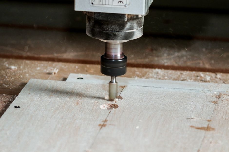
An AM cell that runs to print-part metallurgical spec is no longer just a laser and a recoater — it is a multi-loop control system combining melt-pool pyrometers, layer-wise thermal imaging, oxygen and humidity probes, and an industrial PLC that drives laser power, scan strategy, and recoater speed in real time.
Process control discipline is what separates a research printer from a qualified production line: ASTM/ISO AM standards now expect monitored builds, and buyers evaluating 3D printing production lines in 2026 routinely score vendors on sensor coverage, closed-loop latency, and traceability of the build record.
Sensor Stack: What Is Actually Measured During a Build
A metal powder-bed fusion cell typically carries three to five in-situ sensors per build chamber: a coaxial or off-axis photodiode or pyrometer aimed at the melt pool, a thermal camera imaging the full plate, an oxygen probe (commonly zirconia-cell, setpoint 100–1000 ppm O₂ for Ti-6Al-4V) and a humidity/temperature probe at the powder-handlock [S1]. Polymer SLS and FFF lines replace the oxygen probe with a nitrogen or dry-air dew-point sensor (typically ≤ -40 °C dew point for polyamide 12) and add chamber thermistors at the build and powder-bed planes.
For LPBF stainless 316L and Inconel 718 work, the consensus thermal window — published in multiple peer-reviewed process-window studies in Additive Manufacturing (Elsevier ISSN 2214-8604) [S3] — is a melt-pool length of roughly 200–500 µm and a measured pyrometer temperature in the 1500–1900 °C band, with keyhole-mode collapse above the upper end and lack-of-fusion porosity below the lower end. Slicing and process-improvement papers in the same journal track the same indicators on polymer and composite raster patterns, showing the same control philosophy transposed to lower-energy processes.
Layer-wise part geometry is normally checked with a co-located fringe-projection or laser-line scanner that compares each solidified layer to the sliced CAD slice; deviation triggers a build flag rather than a laser stop, because stopping mid-build is the costliest corrective action available.
Closed-Loop Control: PLC, Fieldbus, and Latency Budget
Signals from the melt-pool pyrometer, thermal camera, and oxygen probe feed back to a Beckhoff, Siemens, or Allen-Bradley PLC over EtherCAT or PROFINET IRT, with a typical sensor-to-actuator loop time of 1–5 ms on modern LPBF controllers [S1]. Two control layers are standard: a fast inner loop that modulates laser power (typically 100–1000 W fibre laser) to hold melt-pool area, and a slower outer loop that adjusts scan strategy and hatch spacing when the thermal camera flags cumulative heat buildup.
Layer-recoater control is handled by the same PLC through a digital I/O block tied to the recoater drive, the powder-feed piston, and the overflow sensor; the interlock logic is a documented portion of the AM-cell functional safety file. Process calibration, parameter-set management, and build-recipe loading run on a higher-level SCADA or industrial PC that exposes a structured build log — this log is the artefact buyers audit when they later validate part pedigree against a additive manufacturing quality standards framework.
Engineering teams sourcing the automation stack increasingly rely on instrumentation and control specialists for build, qualification, and sustainment of the control layer [S2]; MLS Technologies, for example, has staffed embedded controls, automation, and AI/ML roles into nuclear, defence, and advanced-manufacturing programmes since 2000 [S2].
Digital Twin and Model-Based Feed-Forward
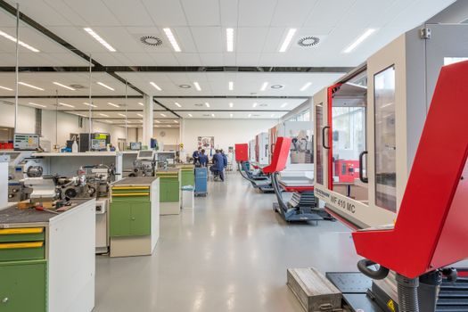
The thermal-mechanical simulation workflow illustrated by Ansys Additive Suite feeds residual-stress and distortion predictions back into the slicer, where the print planner pre-compensates contour geometry before the build starts [S1]. This feed-forward path is complementary to, not a replacement for, in-situ closed-loop control: the twin compensates for systematic warpage that no real-time sensor can correct mid-build, while the pyrometer-and-camera loop absorbs stochastic laser power and powder-layer variation.
For multi-laser LPBF systems (4-laser builds are now mainstream in aerospace part production), the twin also models inter-laser thermal interaction and assigns non-overlapping scan regions — without this, the closed-loop control only sees the local melt pool while adjacent scans drive cumulative plate distortion out of spec.
Selection Criteria: Scoring a Control Package
Four criteria separate a serious production AM control package from a lab retrofit:
1. Sensor count and provenance — confirm coaxial pyrometer, off-axis thermal camera, O₂ probe, and a layer-profilometer are all on the BOM, not optioned. Camera frame rate ≥ 100 Hz is typical for LPBF; slower imagers cannot resolve scan-vector-level events.
2. Closed-loop latency and openness — EtherCAT or PROFINET IRT backplane, documented loop time, and an exposed API for the build log. A closed proprietary stack blocks integration with the plant's control cable and historian.
3. Standard compliance hooks — the HMI should expose ASTM F3434 (in-situ process monitoring), ASTM F3301 (data processing for AM), and ISO/ASTM 52920 (process parameter documentation) fields directly, so that a build record maps 1:1 to a standard clause for later audit.
4. Functional safety integration — the PLC should sit on the same safety bus as the chamber-door interlocks and the laser emergency-stop, with a documented SIL category in the cell's safety file.
Limits and Failure Modes

Closed-loop control cannot rescue a build once a layer-level defect (recoater streak, gas-flow disruption, humidity excursion) is laid down — the defect is already in the part. Sensor windows fog and coat during long builds; pyrometer drift over a 200+ hour production week is non-trivial and demands a documented re-calibration cadence against a blackbody source. [S2]
For polymer AM, the analogous control risks are chamber dew-point creep, powder moisture absorption, and the absence of a sharp thermal signal — pyrometers tuned for metallic melt pools do not transfer cleanly to SLS nylon, and vendors often disable or down-rate the inner loop on polymer machines. The honest engineering answer is that polymer AM closed-loop control lags metal AM by roughly one product generation.
Costs, Lead Time, and Where the Money Goes
For production buyers, the cost engineering of an additive manufacturing process control stack should be reviewed against the part cost drivers in any current 3D printing part cost breakdown because sensor and PLC cost scale with build-chamber area, not part volume. [S2]
Trackable signals for the next 90 days: ASTM F42 committee ballots on monitored-build data retention, vendor disclosures of SIL category on the cell-level safety bus, and a steady downward drift in LPBF scrap rates as inner-loop control matures from optional to standard. Procurement teams should also weigh control-stack depth against OEM-vs-ODM service scope laid out in any current 3D printing OEM vs ODM spec map before signing.
Component reference pages worth checking: multifunction process calibrator.