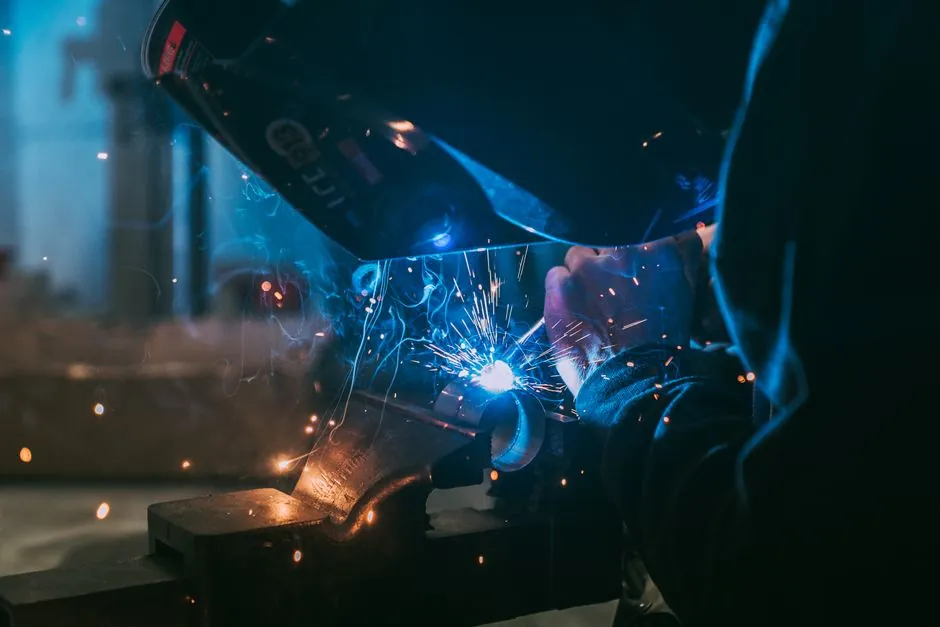
For interior finishing work the dominant arc-welding process is Gas Metal Arc Welding (GMAW/MIG), with output ranges of 20–220A on 120V/230V dual-voltage inverters handling mild steel from 0.6 mm sheet up to ~3 mm structural clips without warping the substrate [S2].
Stick (SMAW), MIG/GMAW, and TIG/GTAW cover the three operating envelopes a finishing crew will meet on site: stick for dirty outdoor tie-in, MIG for clean shop productivity, TIG when the bead has to be invisible on stainless or aluminum trim [S1][S4]. The machine class, not the brand sticker, drives weld quality and rework rates, so the selection is process-first, output-second, voltage-third.
Process Selection: MIG vs TIG vs Stick for Closed-In Spaces
MIG/GMAW is the easiest arc-welding process to learn and is the only one that welds both light-gauge sheet and thicker plate (with multiple passes) at production speed, which makes it the default for a finishing crew that does not run a dedicated welder per worker [S3]. The trade-off is shielding gas sensitivity: a 5–8 km/h cross-draft will spoil porosity on a closed site the moment a door is propped open, so a finishing foreman either schedules MIG around HVAC balancing or switches to gasless flux-cored wire for the messy days [S1][S2].
TIG/GTAW is the only practical answer for thin stainless reveals, aluminum trims, and any joint that will be visible after powder coat, because the non-consumable tungsten electrode and inert argon shield let the operator lay a bead under 1 mm wide without spatter or slag to grind out [S1][S2]. Stick/SMAW is left for the genuinely outdoor or repair tasks, where its flux coating tolerates rust, paint, and wind that would otherwise scrap a MIG bead, and where the slag layer is acceptable because no decorative finish follows [S4][S5].
Output Range and Duty Cycle: Matching Amperage to the Thinnest Member
For 0.6–1.2 mm cold-formed steel studs and 0.9–1.5 mm EMT/conduit hangers, a 120V MIG with a 20–140A output window and a 20% duty cycle at 90A is enough to run 0.6 mm ER70S-6 wire without burn-through; pushing the same machine above 160A on thin stock will blow holes faster than a trainee can back off the trigger [S2]. Crews that handle 3 mm embed plates and rebar chairs at the same site should size to a 200–220A inverter so the upper end of the range is reserved for the plate, not the daily work.
On the TIG side, a 120V/240V unit with 5–160A (AC/DC) covers aluminum from 0.8 mm up to about 4 mm in a single pass; below 5A the arc becomes unstable on modern inverter TIG, and above 200A the operator is no longer finishing trim but welding structural members, which is a different crew and a different job hazard analysis [S2]. Stick output windows on finishing sites are almost irrelevant, because a finishing foreman will spec stick only as a fallback and the limiting factor is electrode diameter, not amps.
Input Power and Site Electrics: 120V vs 240V Decision

120V input is the right answer for interior finishing because the receptacle already exists on every level, extension cords are legal, and a 20A branch circuit sustains a 90–140A MIG output indefinitely within its 20% duty cycle envelope [S2]. 220V/240V input delivers the same MIG machine up to 200–220A but requires a dedicated 30–50A branch and a NEMA 6-50 or equivalent receptacle that the finish carpenter will not have installed; sites that are 240V-only can still use a dual-voltage inverter switched to 120V for trim work [S2].
Dual-voltage MIG/Stick multi-process units in the 40 lb class (e.g. the 120V/230V, 20–220A bracket) are the most flexible single purchase for a finishing crew that moves between tenant improvements, retail fit-outs, and light industrial retrofits, because the same machine can be plugged into a kitchen receptacle in the morning and a service-panel tap in the afternoon [S2]. A finishing crew should not buy a 510 lb gas-powered 50–300A multi-process unit for interior work; that weight class exists for site welding with no grid power, not for slab-on-grade finishing.
Electrode and Filler Choices That Affect Finished Surfaces
For MIG on mild steel, ER70S-6 wire in 0.6 mm or 0.8 mm diameter is the workhorse filler for finishing crews, because the silicon-manganese deoxidizers tolerate the mill scale and light rust found on site-delivered stud and plate stock [S2]. When the spec calls for galvanized steel (e.g. embeds or pre-galv clips), a 0.8 mm ER70S-3 wire at the low end of the voltage envelope reduces zinc fuming; alternatively, a gasless E71T-11 flux-cored wire eliminates the gas bottle entirely at the cost of more slag to clean off, which is a real problem if the joint will be visible [S1][S2].
For TIG, the consumable is a 1.6 mm or 2.4 mm tungsten (2% lanthanated or 2% thoriated for steel, pure or 1% lanthanated for aluminum) plus a matching filler rod, and 100% argon shielding at 10–15 CFH is standard; deviating to argon/helium mixes on aluminum trim raises cost without finishing-trade benefit [S1]. For stick fallback work, electrode coating choice (cellulosic, rutile, basic) drives arc stability and slag release, and the operator must match coating to base metal, but on a finishing site stick is a contingency, not a daily process [S5].
Comparison of Process Options Against Four Decision Criteria
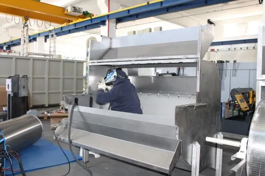
Lining the three processes against the criteria that actually drive a finishing foreman's purchase: MIG wins on operator-skill ramp and deposition rate, TIG wins on bead cosmetics and thin-metal control, and stick wins on environmental tolerance and capital cost [S1][S2][S3][S4]. Cost per linear metre of finished-quality weld runs lowest on MIG, mid on stick (once electrode consumption and slag chipping are counted), and highest on TIG because of argon and the slower travel speed; this is why no finishing crew should buy a TIG as its only machine [S2].
Polarity, Shielding Gas, and the Small Knobs That Prevent Rework
DC electrode negative (DCEN, straight polarity) is used for TIG on steel and aluminum, where ~70% of the heat stays on the tungsten and the workpiece stays cooler, which is exactly what a finishing operator wants on a 0.8 mm trim piece [S1]. AC is reserved for AC TIG on aluminum, where the alternating envelope continuously breaks up the oxide layer that would otherwise contaminate the weld pool [S1].
Shielding gas for mild-steel MIG is typically 75% argon / 25% CO2 (C25) at 20–25 CFH, which gives a stable arc and a clean bead without the spatter of straight CO2; pure CO2 runs hotter but spatters more, which means more grinding on a finished surface [S1]. For stainless, a 98% argon / 2% CO2 blend (or 98/2 argon/O2 for higher travel speed) preserves corrosion resistance in the heat-affected zone, and tri-mix (He/Ar/CO2) is reserved for thicker stainless plate that finishing crews rarely see [S1][S2].
Who This Spec Is For, and Where It Stops Being the Right Tool
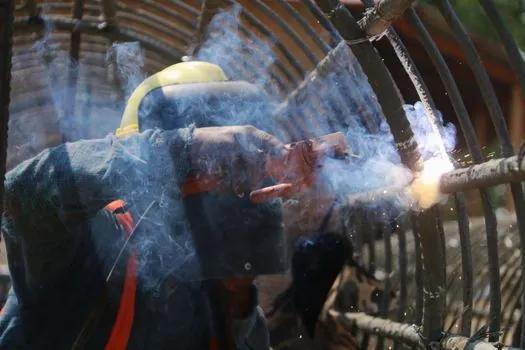
Use this MIG-default spec for interior fit-out crews handling metal-stud framing, light-gauge structural clips, EMT/conduit hangers, equipment embeds, and miscellaneous steel-to-steel trim on tenant improvements, healthcare fit-outs, and data-center white space. Use TIG where the spec calls for visible stainless or aluminum trim, or where a powder-coat or architectural finish is applied over the weld, because MIG spatter will telegraph through any post-applied coating. [S2]
Do not use any of these machines for pressure piping, structural moment connections, or any weld that carries a code-required procedure spec (AWS D1.1 for steel, AWS D1.2 for aluminum, ASME Section IX for pressure) without an actual WPS/PQR on file; finishing-crew hand-held arc welding is not a substitute for qualified procedure welding, and the absence of a procedure is a fabrication audit finding, not a paperwork gap [S3]. For those jobs, hand off to a coded welder and a rebar coupler spec for the connection hardware, not the finishing crew's portable MIG. A laser distance meter spec map covers the layout side of the same workflow, while a rebar straightener spec map handles the embed-prep side that finishes off the welding handoff.
Sourcing, Standards, and Trackable Signals
Cross-reference the arc welder process envelope against the welding cutting tool consumables aisle so electrode, gas, and machine come from one vendor's spec sheet; mismatched regulator flow gauges (CFH vs L/min) are the single most common cause of porosity calls on a finishing site [S1][S2]. For a finishing crew that also runs saws and drills, the cutting machine and finishing material pages round out the consumables picture so the welding purchase is not specified in isolation.
Trackable signals: (1) a finishing foreman should log the wire diameter and gas flow rate at every weld location on the as-built, because the next crew that repairs the joint will not have the original machine's settings; (2) any move from 120V to 240V input on the same machine should trigger a re-check of the supply-cord gauge against the nameplate primary current, because undersized 12 AWG cords on a 30A branch are the most common cause of nuisance breaker trips on finishing sites [S2].