On any VFD-driven load that decelerates faster than the motor's natural losses can absorb, regenerative energy has to go somewhere: a brake resistor sized in ohms, watts, and duty cycle; or a motor specifically built to take the switching stress, a VFD-duty motor [S1][S2].
Commonly stocked industrial brake-resistor families cover 40 W to 30 kW power, 0.1 Ω to 100 kΩ resistance, ±0.5% to ±10% tolerance, and −55 °C to +275 °C operating temperature in aluminum-housed wirewound construction [S3][S4]. A representative VFD-rated brake resistor such as the Delta BR500W100 ships at 500 W and 100 Ω, the exact ohmic range a 230 V-class VFD with a 1.5–3 kW drive expects on its DC bus dump terminal [S5].
Scope: Two Different Problems on the Same Drive Shaft
The VFD itself is the power-electronics front end: an AC motor fed by a PWM inverter, a VFD with a DC bus, and an optional brake chopper [S1]. When the motor acts as a generator — overhauling loads like hoists going down, conveyors running loaded downhill, winders unwinding under tension, centrifuges spinning down, or test dynamometers motoring a prime mover — current flows back into the DC bus and the capacitor voltage rises.
A brake resistor handles that surplus by switching an IGBT across the resistor bank and dumping the energy as heat. A VFD-duty motor, by contrast, does not dissipate regenerative energy at all; it survives the high dV/dt and common-mode voltage from the inverter's PWM output, and it tolerates the elevated bearing currents and reduced-speed self-cooling that come with VFD operation [S1][S3]. Conflating the two leads to mis-sized cabinets: too small a resistor, and the chopper trips; too light a motor, and the winding insulation fails.
Selection Criteria: Wattage, Ohms, and Duty Cycle vs Insulation Class and Bearing Current
Sizing a brake resistor is a thermal and ohmic calculation. The resistor must match the VFD's DC bus voltage, present enough resistance to limit peak current to the chopper's IGBT rating, and dissipate the average braking power without overheating. Stock ranges sit at 100 W to 10 kW, 5 Ω to 500 Ω on the LSBR series [S2], and 40 W to 30 kW with 0.1 Ω to 100 kΩ on the ASZ aluminum-housed family [S3][S4]. Operating temperatures to +275 °C and tolerances between ±0.5% and ±10% let designers trade precision for cost in non-critical applications like elevator and hoist banks [S3].
Sizing a VFD-duty motor, on the other hand, is an insulation and thermal-margin exercise. The motor nameplate must specify "inverter-duty" or "VFD-duty" winding with phase-to-phase insulation rated for the drive's peak line-to-line voltage, typically reinforced with a higher class of magnet wire and vacuum-pressure-impregnated (VPI) epoxy. Above roughly 500 V VFD output (480 V and 575 V classes), the industry norm is to add a shaft grounding ring or insulated bearing to divert bearing currents, plus a separate blower fan if the application runs below the motor's self-cooled base speed for extended periods [S1].
The decision triggers line up cleanly: specify a brake resistor whenever the load can back-drive the motor and the drive is not feeding a regen line; specify a VFD-duty motor on any VFD that runs below ~10–20 Hz for long periods, in cyclic duty, or at long cable lengths where reflected-wave transients damage standard insulation [S1].
Comparison Matrix: Brake Resistor vs VFD-Duty Motor Across Four Criteria
Across four decision criteria, the differences are sharp. <strong>Primary function:</strong> a brake resistor dissipates regenerative energy as heat, 40 W to 30 kW per element in typical catalogs [S2][S3][S4]; a VFD-duty motor tolerates the electrical stress of being fed by a VFD — high dV/dt, common-mode voltage, and reduced-speed cooling — without failing [S1]. <strong>Key selection parameter:</strong> for the resistor it is resistance (Ω) matching the DC bus, continuous power (W), and peak energy (J or kWs) per stop; for the motor it is inverter-rated insulation class, frame size, and bearing protection scheme [S3][S5]. <strong>Failure mode if missing:</strong> without a brake resistor, the VFD trips on DC bus overvoltage during fast decel; without a VFD-duty motor, standard induction windings fail from insulation breakdown, and bearings pit from EDM-style current discharges [S1]. <strong>Typical installed cost band:</strong> a 500 W, 100 Ω aluminum-housed brake resistor lists in the $150–$200 retail range, with line items like the Delta BR500W100 at 99.5% positive feedback on a major marketplace [S5]; a VFD-duty motor typically adds 15–40% over a standard TEFC motor of the same kW rating, driven by insulation upgrades and grounding hardware [S1].
Use-Case Routing: Hoists, Winders, Conveyors, CNC, Pumps
For a hoist or elevator with a counterweight, both are mandatory. The motor must be a VFD-duty design to handle the start/stop cycling, and the drive must include a brake resistor sized to absorb the full regen energy of the loaded car — typical resistor selections sit in the 5–50 Ω range at 1–10 kW for 230 V-class systems and 20–100 Ω at 2–30 kW for 480 V-class systems [S3][S4]. A winder or unwinder, with tension-controlled torque, is the same story on a smaller scale.
For a downhill conveyor carrying a heavy load, the regen case dominates and a brake resistor is the primary spec; the motor still benefits from VFD-duty construction because the drive is in continuous torque control. For a CNC spindle or servo feed axis, regen is brief and the drive's internal capacitor plus a small, fast-discharge resistor bank is the norm — most CNC VFDs accept external brake resistors from 30 Ω to 200 Ω at 200 W to 1 kW [S3]. For a variable-torque pump or fan running at 20–60 Hz continuous, regen is rare and a brake resistor is often omitted; the focus shifts to a VFD-duty motor with VPI insulation, a shaft ground, and proper airflow at low speeds [S1].
A practical rule of thumb: any VFD application that asks for decel times shorter than 1.5× the natural coast time needs a brake resistor. Any VFD application that runs the motor below 50% of base speed for more than a few minutes needs a VFD-duty motor.
Integration Notes: Choppers, DB Terminals, and Bearing Currents
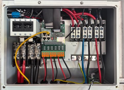
Most modern VFDs expose a "DB" or "P/BR" terminal pair that switches an internal IGBT when the DC bus voltage exceeds a setpoint. The brake resistor wires directly to those terminals; the engineer chooses the resistance to keep peak IGBT current inside its safe operating area, and the wattage to absorb the average braking power [S1][S3]. A thermal switch on the resistor bank can be wired back to the drive's enable input so the VFD trips if the resistor overheats, a common protection on electromagnetic brake and resistor-based stops.
For the motor side, integration centers on cable length and bearing protection. Beyond roughly 15 m of VFD-output cable, peak reflected-wave voltage at the motor terminals can exceed 1.5× the DC bus voltage; an inverter-duty motor with higher phase-to-phase insulation, often called a VFD-duty motor, is the cleanest fix. Beyond 30 m, a sine-wave filter or dV/dt reactor is paired with the motor. A grounding ring on the drive end of the shaft carries bearing currents to ground before they pit the raceways; an insulated bearing on the non-drive end breaks the circulating current loop on larger frames [S1].
Where the application also needs a fail-safe holding function — elevators, cranes, vertical axes — a separate electromagnetic brake or spring-set clutch-brake is added; the brake resistor handles dynamic regen, the electromagnetic brake handles static holding, and the VFD-duty motor survives the duty cycle. Conflating those three jobs is the most common spec error on hoists and stage machinery.
Sourcing Signals and Watch Items
Catalog coverage of brake resistors is broad: 100 W to 10 kW with 5 Ω to 500 Ω on LSBR [S2], 40 W to 30 kW with 0.1 Ω to 100 kΩ on ASZ [S3][S4], and standard 500 W, 100 Ω modules readily available at $150–$200 retail [S5]. The ohmic spread of an order of magnitude inside a single series is a sign of how much VFD sizing varies across the 230 V, 400 V, and 480 V classes. Watch items for the next quarter: supply on aluminum-housed wirewound bodies, lead times on custom-ohmic-value assemblies, and whether VFD manufacturers start publishing default resistor selection tables by motor kW instead of leaving it to the panel builder. For engineers specifying a brake resistor into a new build, the practical next step is to pull the VFD's recommended resistance and minimum wattage from its manual, then size the resistor for at least 1.5× the calculated average braking power to keep the bank out of thermal saturation during repeated stops.
For related coverage, see Fieldbus Gateway vs Remote I/O Module: Protocol-Bridge or I/O-Density Decision.