Industrial electrical connectors are built around four converging process lines — precision metal stamping, selective plating, thermoplastic or thermoset housing molding, and automated contact insertion — and every spec lever in a connector datasheet traces back to one of those lines [S1][S4].
The reference catalogue《电连接器选用手册》organises the field into three families — low-frequency, printed-circuit-board, and RF connectors — spanning circular and rectangular shells, 1 to several hundred contacts per housing, and applications from signal to power, with selection driven by environment, current rating, frequency and mechanical life [S4]. The four process lines below explain how those datasheet numbers are produced.
Stamping and Machining of Contacts and Shells
Phosphor-bronze, beryllium-copper and brass strip in thicknesses typically running 0.10 mm to 0.30 mm feeds high-speed progressive stamping presses that form the male pin, female socket, and the cantilever spring that gives a connector its normal force and mating cycle rating [S4].
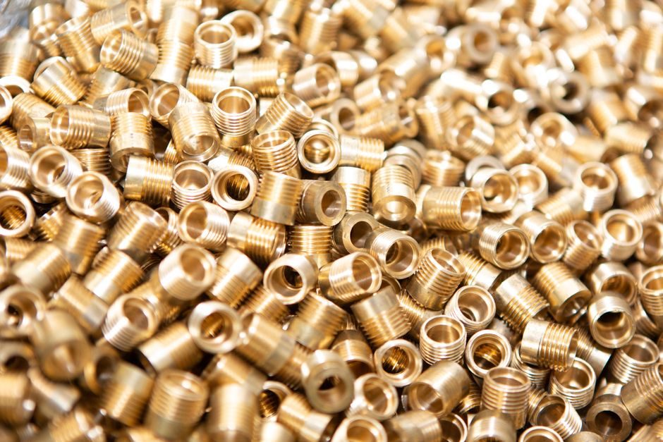
Shells and backshells for circular connectors are usually screw-machined brass or stainless steel, with aluminium alloy variants specified where weight matters; the catalogue distinguishes machined shells from stamped-and-formed shield cans used in board-level RF and high-speed I/O [S4]. Tooling wear on a single progressive die typically drives tolerance accumulation across the contact lot, which is why contact pitch on fine-pitch board-to-wire products is verified post-plating rather than after stamping alone.
Plating Line and Surface Engineering
Contact plating is the lever that defines mating-cycle life, contact resistance (commonly specified in the low milliohm range) and corrosion behaviour. The standard stack is a nickel underplate from roughly 1.27 µm to 2.54 µm, with a gold flash of 0.05 µm to 0.10 µm for signal contacts and a thicker gold or tin-lead finish for power contacts [S4]. Selective plating — strip-and-roller or reel-to-reel — is used so the mating zone is noble while the solder tail or crimp barrel stays solderable at lower cost.
For RF connectors the plating spec is tighter: the outer conductor surface must remain smooth to keep characteristic impedance (commonly 50 Ω for coax, 75 Ω for video) within tolerance, so silver or thicker gold is preferred over tin in the mating face [S4]. Selective plating in barrel lines delivers a definite cost saving against full-body gold, but process control around masking and drag-out is the line item that decides yield.
Housing Molding: Thermoplastics vs Thermosets
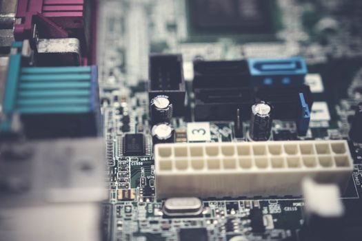
Connector housings are dominated by thermoplastic injection molding — PBT, PA66 (nylon 66), LCP for SMT high-temperature bodies, and PPS for high-end rectangular I/O — with moulded-in latches and polarisation keys formed in the same shot [S4]. Glass-filled grades are used where dimensional stability and creep resistance matter, particularly for through-hole reflow-compatible housings rated to 260 °C peak.
Thermoset and rubber compounds enter at the accessory end: silicone, fluorosilicone and nitrile grommets and interfacial seals give an IP67 or IP68 rating on circular connectors, and the elastomer hardness (commonly 40–60 Shore A) is the lever engineers trade against mating force and temperature range [S4]. This is also where the supplier's tool list — number of cavities, hot-runner layout, cycle time — directly translates into a price band on the BOM.
Automated Assembly, Termination and Test
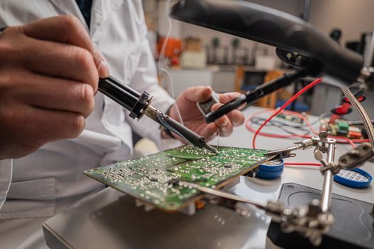
Modern connector lines run reel-to-reel: stamped-and-plated contact strip feeds an insertion press that seats contacts into the housing, with vision systems verifying orientation and height before the part goes to electrical test [S1]. Termination options on the harness side — crimp, IDC, solder — correspond to three different machines on the shop floor, and the crimp pull-force spec (typically tens of newtons depending on wire gauge) is the contractual number called out on the traveller.
End-of-line test usually includes contact resistance, hipot / dielectric withstand, and partial-discharge screening for high-voltage families, plus a 100 % continuity check on signal pins. For context on a different automated line that shares the same vision-and-test discipline, the CNC machine workflow follows a comparable closed-loop measurement pattern, and that overlap explains why moulded-part makers and precision-machining shops converge on the same Tier-1 automotive and rail customers.
Low-Frequency vs PCB vs RF: A Spec Comparison
The three families in the catalogue are best read against four criteria — contact type, dielectric, frequency ceiling, and the dominant process risk [S4]. Low-frequency connectors (rectangular and circular power/signal) use turned or stamped contacts, PBT or PA66 housings, run from DC to a few MHz, and the main defect mode is contact retention and plating wear. PCB connectors — board-to-board, wire-to-board, FPC/FFC — use phosphor-bronze contacts with LCP or PA46 bodies, are pitch-limited from 0.50 mm to 2.54 mm, and the dominant process risk is coplanarity for SMT tails.
RF connectors (SMA, SMB, N-type, BNC) use machined or precision-stamped contacts with PTFE or modified PPE housings, target 50 Ω or 75 Ω, and the main defect mode is impedance drift from plating roughness or dielectric voids. To see the same kind of criteria-based product split in another component family, the LED wafer-to-package flow maps cleanly onto a contact-vs-dielectric-vs-housing split, and the selection logic — pick the contact system, then the housing, then the plating — is identical.
Standards, Ratings and Failure Modes
Connector ratings bundle four independent numbers: working voltage (commonly 250 V to 600 V for industrial), current (1 A signal up to several hundred amps for power), operating temperature (−40 °C to +85 °C is the industrial band, +125 °C and +175 °C for under-hood and aerospace), and mating cycles (often 100 to 500 for industrial, 1 000+ for premium) [S4]. Creepage and clearance on the housing must track the rated voltage and pollution degree, which is why the same 2.54 mm pitch can be specified up to 250 V in one housing and only 30 V in another.
Common failure modes fall into three buckets: contact failure (oxidation, plating wear, loss of normal force), housing failure (creep, thermal distortion, UV or chemical attack) and seal failure (compression set on the elastomer, grommet relaxation after temperature cycling) [S4]. Selecting a connector is therefore a three-axis decision — contact system, housing material, sealing level — and any spec sheet that quotes only pitch and current is hiding the trade-offs.
Selecting a Connector Family for the Job
For signal-level board-to-wire at sub-1 A and below 100 V, a 2.54 mm or 1.27 mm pitch PA66 or PBT housing with tin-plated phosphor-bronze contacts is the default industrial choice, and IDC termination cuts harness labour. For higher currents (above ~10 A per contact), move to power connectors with machined copper-alloy contacts, silver plating at the mating zone and a housing rated to UL94 V-0. [S1]
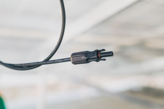
For harsh environment (IP67/IP68, −40 °C to +125 °C), circular connectors with silicone seals and threaded or bayonet locking dominate the BOM; for high-speed data, RF or signal at >1 GHz, the housing and contact stack changes entirely — PTFE or LCP dielectric, 50 Ω controlled impedance, and gold-plated centre conductors. The same supplier-tier logic that separates bearing makers into process specialists and assemblers applies here: Tier-1 connector makers own the stamping die and the plating line, Tier-2 buy stamped contacts and compete on housing and assembly, and the BOM unit price tracks that line tightly.
Trackable signals: the 2024-09-16 issue of《电连接器选用手册》remains the cleanest Chinese-language taxonomy of the field [S4], and supplier-side sourcing reality follows the pattern seen across discrete-component industries — including industrial valves — where Tier-1 vertically integrated lines sit on 12–16 week lead times while Tier-2 assembly houses quote 4–6 weeks on equivalent part numbers.
For component-level specifications, see pressure transmitter, flow meter, and industrial valve.