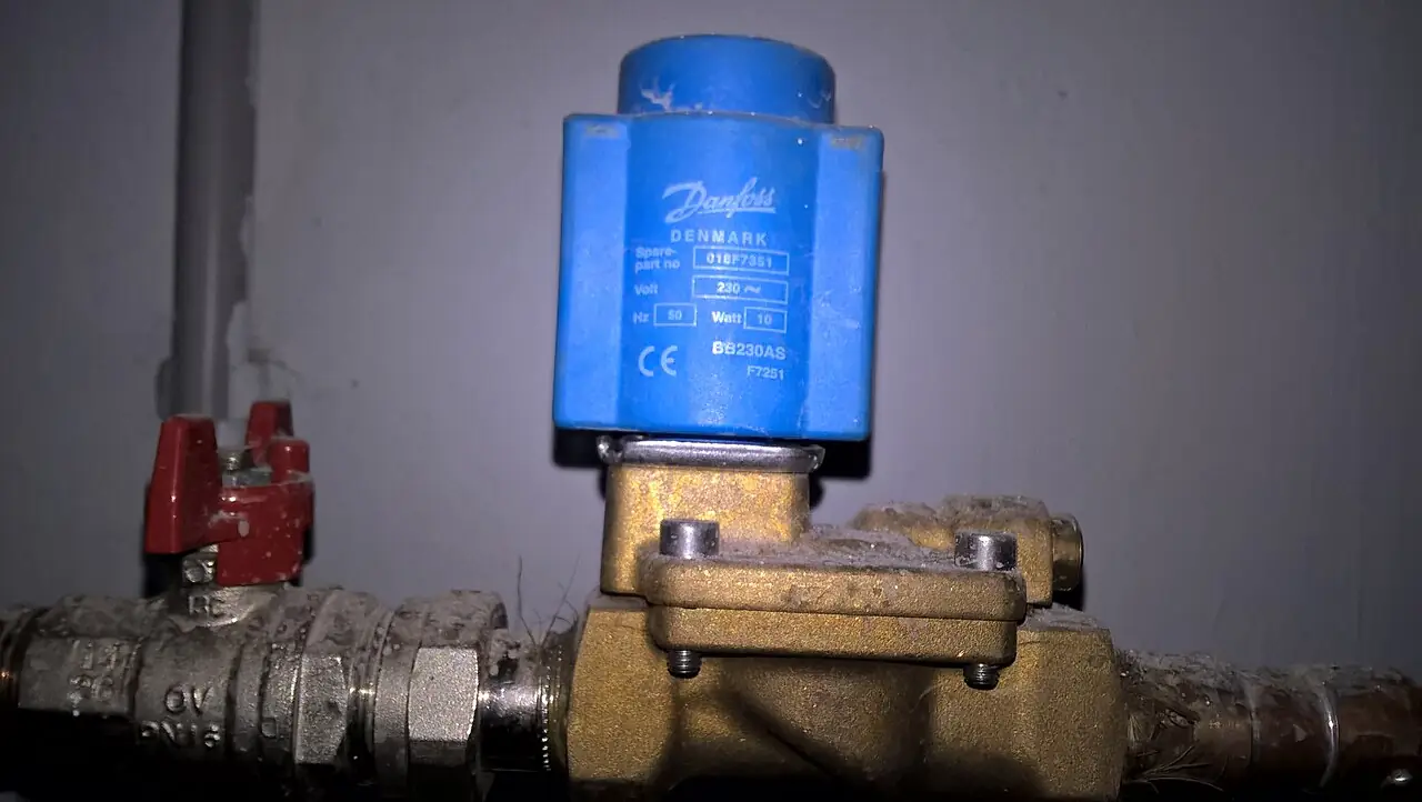
A directional control valve is the traffic switch of fluid power: it starts, stops, and above all reverses the path that hydraulic oil or compressed air takes through a circuit, so a hydraulic cylinder extends or retracts, a hydraulic motor spins either way, and a pneumatic cylinder strokes home or out on command. The valve is described by ways and positions, a 4/3 valve offering four ports, pressure, tank or exhaust, and two work lines, and three spool positions, and its identity lives in the spool or poppet geometry that connects those ports in each position. It is the central valve of every press, injection machine, machine tool, and excavator hydraulic circuit, and its pneumatic siblings run the clamping, handling, and packaging world by the million, actuated by solenoids, air pilots, cams, and hands.
Specifying one is five linked decisions: the ways and positions the circuit needs, 2/2 through 5/3, with the center or neutral condition for three-position valves deciding what the actuator does when the valve is uncommanded; the stage architecture, direct solenoid or pilot-operated, which decides the flow ceiling and the minimum pressure at which the main stage actually shifts; the mounting interface, ISO 4401 subplate sizes NG6 through NG32 or cartridge and threaded builds, which locks the manifold ecosystem the plant will live with; the actuation chain, solenoid voltage and duty, air pilot signal source, manual overrides, and failure behavior on power loss; and the leakage and cleanliness requirements that separate spool valves, with their small inherent leakage, from poppet and seat-sealed designs that hold tight at rest. This page works each decision with catalog numbers and closes with the RFQ lines that make directional valve quotes comparable at engineering level.
This page treats the directional control valve as a circuit element with an exact grammar: ways and positions, spool center conditions and their symbol language, ISO 4401 size ladders, pilot versus direct staging, solenoid and air pilot actuation chains, and the RFQ lines that carry the whole specification.
Chapter 1 / 06
What a Directional Control Valve Is and What Is Being Decided
The grammar comes first, because every catalog conversation is held in it. Ways are the ports the valve owns; positions are the distinct states its internal element can take. A 2/2 valve is a simple make or break. A 3/2 valve, three ports, two positions, vents one work line while pressurizing the other, the single-acting cylinder and piloted drain valve element. The 4/2 connects pressure to one work port and the other to tank, then swaps, driving a double-acting actuator one way or the other with no rest state. The 4/3 adds a neutral position, and the neutral is where the engineering hides: all ports blocked holds the actuator rigid but traps pressure, all ports open to tank floats the actuator and unloads the pump, pressure port blocked with work ports to tank lets the cylinder drift under load, and regeneration or pressure-port-to-work connections shape the behavior further. The five-port pneumatic valve, 5/2 and 5/3, does the same work for air with separate exhausts per side. Naming the center condition letter, in the ISO 1219 symbol grammar every hydraulic engineer reads, is specifying the machine's rest behavior in one character.
What is being decided is therefore not one valve but a place in a circuit. First, the actuator duty: which cylinder or motor, which direction logic, which fail state on power loss, floating or held or last position. Second, the flow and pressure: the circuit's liters per minute at rated pressure set the valve size, and the size sets the mounting interface, so flow is an architecture decision before it is a catalog row. Third, the actuation chain: solenoid-direct up to mid sizes, pilot-operated beyond, with pilot pressure internally supplied or externally vented, and manual overrides so a maintenance crew can stroke the machine with the panel dead. Fourth, the environment: hydraulic versus pneumatic medium, cleanliness class of the oil, ambient and fluid temperature, and the electrical area classification that picks the coil. Fifth, the dynamics: switching time and the shock that switching generates, because a 40-millisecond shift at 300 bar is a hammer unless the spool has notches or the circuit has cushioning.
The competitive frame keeps the selection honest. Against the process solenoid valve, the directional valve is a different citizen: the solenoid valve page treats the process-pipe isolation machine for steam, water, and gas lines, while the directional valve lives inside fluid power circuits at pressures and cycle counts the process world never sees, and the two share only the coil. Against the proportional valve, the directional valve is the switched, not modulated, member: it decides direction and rest state, while the proportional valve grades flow continuously for servo-grade motion, at several times the price and with its own cleanliness demands. Against a bank of cartridge logic elements, the subplate directional valve owns compact machines; the cartridge valve owns high-flow die-casting and press manifolds where a screw-in element per function beats a stacked spool block. Against the check valve and needle valve families, there is no common duty: those are single-direction passive and throttling elements, while the directional valve is an active router. And where the machine's question is how fast rather than which way, the answer is a flow control or a VFD on the electric side, not a different letter of center condition.
One positioning note: this page is the single-product page for the switched directional valve in both hydraulic and pneumatic power. The solenoid valve, the hydraulic cylinder, the pneumatic cylinder, and the proportional families each have their own pages; here the assumption is direction and state control of a fluid power circuit, and every number that follows is chosen for that world.
Chapter 2 / 06
How Spool and Poppet Valves Switch Flow Paths
The spool valve is a precision piston with lands and grooves sliding in a bore with tiny clearance, typicallly a few micrometers. Each position aligns the grooves with different port windows in the bore, connecting pressure to work and work to tank in the pattern the symbol draws; shift the spool a few millimeters and the pattern swaps. The spool never seals mechanically: it leaks across its lands at a rate set by clearance, viscosity, and pressure, a few cubic centimeters per minute for a quality NG6 hydraulic valve and a fraction of that for small pneumatic spools, and that leakage is a datasheet line, not a defect. The spool's virtues are speed, low actuation force because the moving element is pressure-balanced, and an enormous catalogue of functions: notches cut into the switching lands meter the transition so the shift is progressive rather than a shock, and the same body serves dozens of center conditions by changing only the spool.
The poppet valve is the opposite trade: a seat-sealed element, a cone or ball pressed onto a seat by pressure and springs, opened by an actuator or pilot force. A poppet holds bubble-tight at rest, which the spool cannot, and tolerates moderate contamination better than a close-clearance bore; its price is a force imbalance, the line pressure acts on the poppet area so the actuator must overcome it, and its response and flow capacity per size are lower. Directional valves built entirely from poppets serve the zero-leakage duties, holding a load for days without drift, and most practical pneumatic valves are spool-with-seals or poppet hybrids in which the actuation stage and the sealing stage differ. The selection question "can the load be allowed to creep" is really the question "spool leakage is it acceptable", and the answer decides the architecture.
Actuation stages ladder by force and flow. The direct solenoid coil moves the spool itself: simple, fast, typicallly 10 to 45 milliseconds for a size NG6 wet-pin DC design, but force-limited, so direct operation tops out in the mid flow ranges, an NG10 direct valve at around 120 liters per minute is near the practical ceiling, beyond which the coil would need to be the size of the machine. The pilot-operated valve solves it: a small direct stage, solenoid or air pilot, drives a larger main spool using system pressure as the force amplifier, which is how NG16 through NG32 valves switch hundreds to a thousand liters per minute with the same compact coils. Pilot plumbing has its own grammar, internal or external pilot supply, internal or external drain, four combinations, each right for a different circuit: low-pressure systems need external pilot supply to guarantee shifting force, and systems with back pressure in the tank line need an external drain so pilot oil is not fighting it. The minimum pilot pressure line in the datasheet, commonly 3 to 5 bar for hydraulic main stages, is a hard floor, not a suggestion.
Actuation
Typical flow ceiling
Switching time
Where it wins
Direct solenoid, wet-pin DC
to about 120 L/min at NG10
10 to 45 ms
Machines, general duty
Direct solenoid, AC
similar by size
10 to 30 ms
Legacy panels, fast pull-in
Air-piloted pneumatic spool
large Cv pneumatic duty
tens of ms
Explosive-proof remote signaling
Pilot-operated, solenoid stage
to about 1,000 L/min at NG32
30 to 120 ms by size
Presses, high flow
Manual, mechanical, cam
by size class
operator-paced
Safety stroking, sequencing
Failure behavior is designed, not discovered. Spring-return valves, one coil and one spring in the simplest form, or two springs centering a two-coil spool, return to a defined position on power loss: the center condition for 4/3 spring-centered designs, the offset position for 2-position spring-return valves, and the choice must match the machine's hazard analysis, a press that must open or a load that must hold. Detented or mechanical-memory two-coil valves stay in the last position, pulse-and-hold, saving coil power on long states and buying the obligation to design what happens on a plant blackout. Manual override levers or pins belong on almost every solenoid valve in a maintenance context, because they let a technician stroke the circuit with the electrical panel locked out, and their absence turns every commissioning setback into an electrical exercise.
Shock and metering close the physics. A sudden full shift at high pressure and high flow sends a pressure spike down the line, water hammer in oil form, that shakes fittings and wakes the neighborhood; the engineering answers are notched or tapered spool lands that meter the transition over the last portion of travel, switching-time options, and circuit-level cushioning on the actuator itself. The datasheet's flow rating is stated at a reference viscosity and a stated pressure drop, commonly several bar across the valve at rated flow, and reading the pressure-drop curve at the real flow, not the rated flow, is the difference between a machine that runs and a machine that runs 10 percent slow with hot oil.
Chapter 3 / 06
Types, Construction, and Duty Boundaries
Hydraulic subplate valves divide by the ISO size ladder. NG6, the ISO 4401-03 or NFPA D03 pattern, is the universal machine-building size: flows to about 60 or 80 liters per minute, pressures commonly to 315 or 350 bar, two-coil or one-coil bodies, dozens of spools. NG10, D05, carries roughly 120 liters per minute and the mid machines. NG16 and NG25 serve presses and plastics machinery at several hundred liters per minute, mostly pilot-operated; NG32 tops the subplate family near 1,000 liters per minute. The mounting faces, port patterns, and tie-rod or bolt spacings are standardized, so a manifold drilled for ISO 4401 size 06 accepts any maker's valve of that size, which is the standardization that makes the technology an ecosystem. Threaded cartridge valves, screw-in elements in a common cavity to ISO 7789 and its family, build high-flow blocks without subplates; logic elements, the two-port poppet inserts, combine with smaller directional pilots into press manifolds of arbitrary flow. Pneumatic directional valves live by their own size ladder, from the 18 and 26 millimeter valve islands of the electronics world to the heavy 52 millimeter spools for large cylinders, with flow quoted as effective Cv or nominal flow in liters per minute ANR, from a few hundred on valve-island monoblocks past 6,000 for the largest.
Construction follows the medium's discipline. Hydraulic valves are steel: ground bores, hardened spools, high-strength housings, and a cleanliness regime expressed in ISO 4406 codes, because the micrometer clearances that make a spool valve work are the first casualty of dirty oil. Pneumatic valves are aluminum and polymer, sealed spools running in elastomer-lined bores, light, fast, and tolerant of ordinary plant air that is filtered and oiled per the maker's regime. Coil options cross both worlds: DC 24 volt the modern default, wet-pin armatures running in the oil or air quietly, AC legacy coils with their higher inrush and burnout-on-stuck-spool failure mode, connectors to the DIN 43650 family or M12 industrial round, and LED and varistor options inside the plug. Subplate valves bolt on with their ports sealing on the manifold face; in-line pneumatic valves thread or clamp into manifolds and islands; cartridge valves screw into cavities with torque specs that matter.
Type
Typical envelope
Duty where it wins
Hard boundary
NG6 subplate spool, 4/3
to 80 L/min, 315 bar
Machine building default
Spool leakage holds no load
NG10 direct or pilot
to about 120 L/min
Mid-size presses, plastics
Direct coil force ceiling
NG16 to NG32 pilot-operated
to about 1,000 L/min
High-flow press manifolds
Pilot pressure floor must exist
Poppet seat-sealed directional
mid flows by design
Zero leak hold, water hydraulics
Force imbalance, slower
Cartridge and logic elements
effectively unlimited by count
Die casting, press blocks
Manifold engineering required
Pneumatic valve island, 5/2 and 5/3
Cv by station, to thousands L/min
Automation, clamping, packaging
Air-only medium and pressure
Duty boundaries, sentence by sentence. General machine motion, extend, retract, hold or float: the subplate spool valve owns it, sized by flow at real pressure drop with the center condition chosen by hazard review. Holding a load for long periods without drift: poppet designs or pilot-to-check circuits, because the spool leaks and the load creeps. Explosion-hazard plants without elaborate electrics: air-piloted pneumatic directionals driven by remote solenoid pilots, the classical intrinsically-safe-by-medium solution. High-flow press and die-cast duty: cartridge logic blocks engineered as manifolds, not catalogs of subplate valves. Servo-grade motion with position feedback: the proportional and servo families own it, this page's switched world ends at open-loop speed control. Process line isolation for steam and water: the process solenoid valve and its kin, a different pressure, temperature, and standards world. Manual machine stroking and safety positions: manual and detent options specified at purchase, not improvised with wrenches on solenoid tubes. The electrical and motion neighborhood belongs on the same drawing: the PLC energizes the valve coils through an industrial relay or its own output card, the proximity sensor confirms end of travel on the machine axis, the soft starter and the drive manage the motor side of the station, and the quarter-turn isolation siblings, the ball valve and the plug valve, share the skid's shutoff duties with the directional function. Each boundary is a physics and standards statement, and Chapter 5 turns each into an RFQ line.
Chapter 4 / 06
Key Specification Parameters
The decode table is the datasheet skeleton. Every row is an RFQ line, and the two right columns are what each row decides and what it costs to leave blank.
Parameter
Typical catalog spread
What it decides
Ways and positions
2/2, 3/2, 4/2, 4/3, 5/2, 5/3
Circuit grammar and actuator logic
Center or offset condition
blocked, open tank, floating, regeneration by letter
Rest behavior and fail state of the machine
Size and mounting interface
ISO 4401 NG6 to NG32, cartridge, pneumatic island
Manifold ecosystem and flow ceiling
Rated flow at pressure drop
NG6 about 60, NG10 120, NG32 about 1,000 L/min
Real capacity at the circuit's drop budget
Maximum pressure
315 to 350 bar hydraulic, 10 to 16 bar pneumatic
Envelope against system relief setting
Actuation and return
solenoid, air pilot, manual; spring, detent
Control chain and defined failure position
Voltage and coil class
24 V DC, 230 V AC, DIN 43650 or M12
Panel compatibility and duty rating
Pilot architecture and minimums
internal or external supply and drain, 3 to 5 bar floor
The flow row is the one that separates engineering from quotation exchange. A valve's rated flow is quoted at a stated pressure drop across itself; read the curve at your circuit's acceptable drop and the same valve is suddenly a size larger or smaller. Sizing on nominal pipe intuition overspends, sizing on rated flow at the reference drop under-spends, and the honest line in the RFQ is: required flow, acceptable valve pressure drop, and the resulting size, with the manufacturer's curve attached to the quote. The pressure row pairs with it: the system relief setting, not the pump nominal, is the pressure the valve holds daily, and momentary spike ratings above continuous belong in the datasheet reading, not in the selection optimism.
The center condition row is the one that decides what the machine does at lunch. Blocked centers hold actuators rigid and trap trapped-line pressure that must be relieved for safe maintenance; open centers unload the pump and float the load, wasting position but saving energy and heat; work-to-tank with blocked pressure lets loads drift gently to rest; regeneration connects rod side to bore side for fast approach strokes. The same machine often wants different answers per axis, which is why multi-valve manifolds mix spools. Write the letter and the meaning in the RFQ, because "closed center" and "blocked center" and vendor letter codes have collided in more commissioning meetings than any other single line.
The actuation rows decide the control chain's honesty. Coil duty rating, continuous or short-period, matters for detent alternatives and for applications that hold one coil energized for hours; wet-pin DC coils with the rectifier in the plug are the low-maintenance default, and AC coils' burnout-on-blocked-spool failure mode belongs in the reliability review. The manual override option costs little and saves every commissioning; specify it visibly. For pilot-operated stages, the four-way pilot plumbing choice, internal or external supply and drain, is a circuit decision with a jumper or a plug on the valve, and the minimum pilot pressure at the worst-case operating point, commonly 3 to 5 bar, must be demonstrated in the circuit, because a main stage that will not shift below 4 bar in a system that idles at 3 is a machine that mysteriously works only at high pressure.
The certificate stack is the delivery ticket: material and pressure-test evidence for the housings, coil conformity with the low-voltage directive and, where required, ATEX or IECEx marking for the area class, CE conformity of the valve assembly, and on audited projects the cleanliness declaration, oil-washed and capped, that keeps the plant's ISO 4406 target from being murdered at installation. A quote missing the stack is not cheaper, it is later.
Chapter 5 / 06
Selection Decision Factors and RFQ Language
The decision sequence runs from the machine's motion outward, because every later step prices the earlier one.
Draw the motion requirement per axis: directions, rest states, fail state on power loss from the hazard review, and hold versus float versus drift behavior at idle, which writes the ways, positions, and center condition directly.
Compute the flow at each state from actuator size and cycle speed, set the acceptable valve pressure drop with the thermal budget in mind, and read the size ladder, NG6, NG10, NG16, to the curve, not the label.
Choose the stage architecture: direct solenoid while the flow allows, pilot-operated beyond, with the pilot supply and drain routing chosen for the circuit's pressure range and the minimum pilot pressure demonstrated at worst case.
Fix the actuation chain: coil voltage and duty, connector family, manual overrides on every station, and air-pilot staging where the area classification or the panel philosophy wants air in the hazardous zones.
Match the medium discipline: hydraulic cleanliness target with the filtration that enforces it, pneumatic air quality per the maker's regime, fluid temperature window against the site's extremes, and the spool-versus-poppet decision wherever a load must hold without creep.
Plan the integration: manifold or island pattern, subplate or cartridge, spare stations for the functions the machine will grow next year, and the electrical schematics' coil and feedback wiring.
Close with the commercial lines: spool code per station with its symbol drawing, switching time at operating conditions, leakage statement, delivery with cleanliness plugs, and the spare coil and spool kit pricing against the machine's downtime rate.
The cost comparison is installed cost per function over the machine's life. A quality NG6 valve prices modestly; a manifold of six with the wrong center conditions prices a machine redesign. Against the proportional alternative, the switched directional valve is a fraction of the cost and a fraction of the capability, and the boundary is honest: open-loop motion at machine speeds belongs here, closed-loop position and pressure profiles belong to the proportional page. Against cartridge blocks, the subplate family wins below several hundred liters per minute on engineering cost and serviceability, and loses above it on physical size. The pneumatic island against discrete valves prices on stations and wiring: an island with a fieldbus or multi-pin connector moves the electrical cost into one cable, which is why the island has been eating the discrete-valve market for twenty years. Table the decision on cost per reliable cycle, including the coil that burns, the spool that sticks, and the override nobody fitted.
Duty
Configuration to specify
Watch line
Machine axis, extend and retract
4/3 NG6 or NG10, spring-centered, notched spool
center condition letter
Load must hold for hours
Poppet directional or pilot-to-check circuit
spool creep arithmetic
High-flow press function
NG16 to NG32 pilot-operated, external drain
minimum pilot pressure floor
Explosive-atmosphere plant air
Air-piloted pneumatic directional, remote pilots
pilot signal tubing quality
Clamping and packaging stations
5/2 and 5/3 valve island, multi-pin or bus
stations and spare capacity
Safety stroking access
Manual override pins on every solenoid
visible and lockable
The RFQ language that makes quotes comparable, written as the datasheet lines a vendor must answer with numbers: ways, positions, and center condition by symbol; size and mounting interface to ISO 4401 or cavity standard; rated flow with the reference pressure drop and the curve; maximum continuous and peak pressure; actuation type and return architecture with the defined failure position; coil voltage, duty rating, connector, and manual override provision; pilot supply and drain routing with minimum pilot pressure; switching time at stated conditions; internal leakage per land at rated pressure; fluid and ambient temperature window; cleanliness delivery state; certificates. A quotation answering those lines is a circuit element with a guarantee; anything else is a block of steel with a coil attached.
Chapter 6 / 06
Installation, Standards, Failure Modes, and Maintenance
Installation follows the discipline the valve was built to. Subplate valves mount on clean manifold faces with the port seals in place and the bolts torqued to the maker's figures, because an undertorqued NG10 face leaks at 300 bar and an overtorgued one distorts the bore and sticks the spool. Cartridge elements screw to cavity torque specs for the same reason. Cleanliness is the installation's religion: caps stay on until the moment of connection, hoses and pipes are flushed before the valve sees them, and the first filter change is scheduled early, because the commissioning period generates the dirtiest oil a valve will ever see. Electrical work is the coil's religion: correct polarity where LEDs care, the rectifier plugs seated for DC coils on AC supplies, and the coil's connector orientation such that a washdown does not live in the socket. Pneumatic installations add the air preparation unit, filter, regulator, and lubrication where the maker's design expects it, mounted within reach and drained.
The standards frame is the fluid power industry's own. Mounting interfaces and cavity dimensions run on the ISO 4401 subplate family and the ISO 7789 cartridge family, with CETOP and NFPA equivalents mapping onto the same physical patterns; symbols and circuit grammar run on ISO 1219, the graphical language every datasheet in this chapter is written in; cleanliness is expressed in ISO 4406 codes with sampling to ISO 4021 practice; coils and connectors answer the low-voltage and electromagnetic compatibility directives, with ATEX and IECEx marking for classified areas. The RFQ does not need to buy the standards, it needs to require the vendor to speak them: a datasheet that names its ISO size, draws ISO 1219 symbols, quotes leakage per land, and declares the delivery cleanliness state is a datasheet the plant can audit.
Failure modes arrive in a predictable order, and each has a specification answer. Contamination sticking shows as the spool hesitating or refusing under load, the classic silting when a machine stands hot and idle: the answer is the cleanliness target enforced from commissioning, flush-before-connect, and the early filter change, plus DC wet-pin coils whose constant light magnetism helps keep the clearance clear. Burnt coils on AC designs show as a dead station after a stall: the answer is DC coils with rectifier plugs and, on any design, the coil insulation class honestly matched to ambient. Pilot starvation on pilot-operated stages shows as shifting only at high system pressure: the answer is the minimum pilot pressure line checked in the circuit, external pilot supply where the system idles low, and the drain routed where back pressure cannot fight it. Seal and housing leaks show as weeps at the manifold face or the end caps: the answer is torque discipline at installation and the seal kit in the spares. Shock damage from unnotched shifts shows as fitting failures and line fatigue: the answer is notched or tapered spools specified at purchase and cushioning on the actuator. Manual overrides painted over show as a maintenance event on a weekend: the answer is the override option, kept visible, on every station.
Maintenance is a small calendar built on oil health. The monthly walk: leak check at faces and end caps, override pins free, connector LEDs correct, island supply pressure at spec. The quarterly or by-sample check: oil cleanliness to the ISO 4406 target, filter deltas, tank temperature against the thermal budget. The annual service: spool function verified by stroke test at pressure, coil current against nameplate on legacy AC fleets, manifold bolts re-torqued after the first thermal cycles, and the spares audit, one coil per station type and one spool per function, because a directional valve is repaired by exchange in hours and rebuilt by schedule in years. Plants that keep the oil clean keep their valves for decades; the valve's own wear parts are few, and the failures that end them were almost always delivered through the fluid.
The commissioning record closes the loop: as-built symbol per station, flow and drop verified against the curve, shifting times logged at pressure, pilot pressure demonstrated at worst case, override function exercised, cleanliness of the first sample recorded. One page per manifold, kept with the machine file. Plants that keep it diagnose by comparison; plants that do not diagnose by folklore, and folklore in fluid power is expensive.
FAQ
What do the numbers in 4/3 or 5/2 actually mean?
The first number is the ways, the ports the valve owns; the second is the positions, the distinct states its spool can take. A 4/3 valve has pressure, tank, and two work ports across three spool states, including the neutral that decides what the machine does at rest. A 5/2 pneumatic valve has two work ports with separate exhausts and two states, driving a double-acting cylinder either direction with no defined rest state.
Which center condition should a 4/3 valve have?
Choose from the hazard review, not the catalog default. All-ports-blocked holds the actuator rigid but traps pressure for maintenance relief; all-open-to-tank unloads the pump and floats the load; work-to-tank with blocked pressure lets loads settle gently. Regeneration connects both work ports for fast approach. Write the symbol letter and its plain-language meaning into the RFQ, because vendor letter codes have collided in many commissioning meetings.
When do I need a pilot-operated valve instead of a direct solenoid?
Above roughly 120 liters per minute, the direct coil's force requirement grows past practical size, and the pilot-operated stage takes over: a small solenoid stage uses system pressure to shift the main spool. Specify the pilot plumbing, internal or external supply and drain, for your circuit, and demonstrate the minimum pilot pressure, commonly 3 to 5 bar, at the worst-case operating point, or the valve will shift only when the system happens to be busy.
Can a spool valve hold a load without creeping?
Not for long: the spool seals by fine clearance and leaks across its lands, a few cubic centimeters per minute on a quality hydraulic valve, so a held load creeps downhill over minutes to hours. For genuine load holding, specify a seat-sealed poppet directional valve or add pilot-operated check valves in the circuit. The load-hold duration requirement belongs in the RFQ as a number, and the spool-versus-poppet choice follows it.
Why does my hydraulic directional valve stick after standing idle?
Silting: fine contamination packs into the spool clearances, a few micrometers, while the oil sits hot and unstroked, and the first shift of the week fights a varnished spool. The answer is cleanliness enforced from commissioning, filters changed early after startup, DC wet-pin coils, and periodic exercise strokes in the control logic. A valve that sticks only after idle weekends is telling you the oil, not the valve, needs attention.
AC or DC coils for a new machine?
DC, typically 24 volt, with rectifier plugs where the panel supplies AC: lower inrush, no burnout-when-blocked failure mode, quieter wet-pin armatures, and simpler intrinsically safe paths. AC coils pull in faster and legacy panels run on them, but an AC coil held against a stuck spool burns in seconds. Specify the connector family, DIN 43650 or M12, with LED and suppression, and the duty rating if any coil will be energized for hours.
How is valve size NG6 versus NG10 actually decided?
By flow at your acceptable pressure drop, read from the maker's curve, not from the port thread. Compute each axis's liters per minute from cylinder size and cycle speed, decide how many bar you will spend across the valve, and the size follows: NG6 carries roughly 60 to 80 liters per minute comfortably, NG10 about 120, with NG16 and above pilot-operated. Sizing on port intuition overspends, and sizing on the catalog's rated flow at its reference drop under-spends your machine.