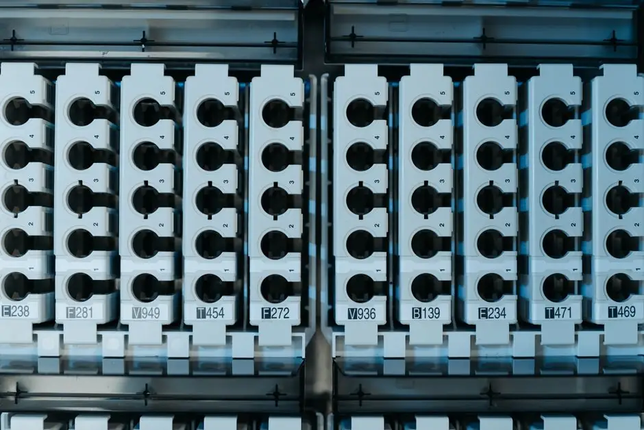
Clamp-on current transformers let a maintenance technician clip a hinged iron or nanocrystalline core around a single insulated conductor and read proportional secondary current at 1 A or 5 A nominal, without ever opening the cabinet or powering the load down [S4].
The mechanism is Faraday's electromagnetic induction: a single-turn primary (the cable itself) drives a multi-turn secondary through a closed magnetic core, so the secondary current equals the primary current divided by the secondary turns ratio [S4]. Split-core, hinged, and flexible Rogowski geometries are all common, with the split-core form factor carrying a small accuracy penalty in exchange for the ability to retrofit around already-terminated conductors [S4].
Operating Principle and Accuracy Class
A clamp CT steps the primary current down by the turns ratio (commonly 100:5, 200:5, 400:5, 1000:5) and presents that reduced current to a meter, protection relay, or ADC input, while providing galvanic isolation between the power conductor and the instrumentation [S4]. For protective relay work, the relevant metric is the IEC 61869-2 accuracy class: 5P and 10P denote composite error at a defined accuracy-limit primary current and burden, and PX (the older "protection class X") is a definite-purpose class used when a relay manufacturer needs to know turns ratio, knee-point voltage, and magnetising current precisely [S5][S6].
For measurement, IEC 61869-2 accuracy classes 0.1, 0.2, 0.5, 1, and 3 cover typical metering service; the smaller the number, the tighter the ratio and phase error across the burden range. A class 0.5 CT is the de facto floor for revenue metering, while class 1 is widely accepted for sub-billing and load-profile work on machine state monitoring [S4]. Split-core units usually sit one or two classes behind their solid-core equivalents of the same core material, because the air gap at the hinge introduces a small, repeatable, but non-zero magnetising current component [S4].
Range, Burden, and Saturation Behaviour
Commercial iron-core clamp CTs span roughly 5 AAC RMS to 1000 AAC RMS as off-the-shelf ranges, with 100 A and 200 A being the workhorse sizes for motor feeders and HVAC compressor circuits [S4]. The secondary must drive a defined burden (the meter's input impedance plus the loop resistance, in VA at rated current), and the chosen CT must keep its knee-point voltage comfortably above that burden voltage even at fault current, otherwise the core saturates and the secondary waveform clips [S4].
Two engineering consequences matter for machine state detection. First, a 5 A secondary rated 5 VA at 20 A primary will saturate well before that level if the actual burden is 1 VA, which is why relaying-spec CTs are sized by the symmetrical short-circuit current I_sc and the true loop impedance, not by the steady-state load alone. Second, harmonic content above roughly 1 kHz is read less faithfully as core material approaches saturation, so a thermal machine with a VFD drive producing strong switching-edge content (typically 2 to 16 kHz) is best served by either a wider-bandwidth ferrite or nanocrystalline core, or a true current transducer with active flux compensation rather than a passive iron-core clamp [S4].
Split-Core vs Flexible Rogowski vs Solid-Core
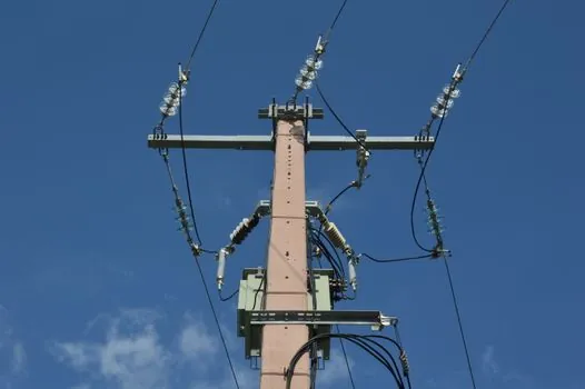
Split-core clamp CTs are the retrofit default: the operator opens the jaw, places it around the cable, closes the latch, and the internal shunt or burden resistor produces a mA-level signal ready for an analog front end [S2]. They tolerate 50/60 Hz fundamental measurement well, are inexpensive, and in the common 100 A AC form factor are routinely specified for branch-circuit energy monitoring and small-motor load profiling [S5]. Flexible Rogowski coils extend the same clamp-on convenience to busbars and large conductors, but output an mV/kA derivative signal that must be integrated, so they are not a drop-in replacement for a CT whose metering expects a 5 A or 1 A secondary.
Solid-core toroidal CTs are the highest-accuracy option because the magnetic path has no air gap, but installation requires threading the conductor through the window before termination, ruling them out for live retrofits. The practical decision matrix is: solid-core for new-build panels where accuracy and cost-per-channel dominate, split-core clamp for retrofits and branch monitoring where ease of installation is the constraint, and flexible Rogowski where the conductor is too large or irregular to clear a rigid jaw [S4]. Reference designs for gas detection panels and motor control centres routinely use split-core CTs in this way, with the secondary feeding a multichannel energy meter or a 4-20 mA transducer.
Integration Path: From Secondary Current to Machine State
The raw secondary current is rarely the final measurement. A burden resistor converts the 5 A or 1 A secondary into a 0-333 mV (for 1 A secondary through 0.333 ohm) or 0-1 V (for 5 A through 0.2 ohm) signal, which an analog-to-digital converter samples at a rate high enough to capture the harmonics of interest [S1]. The ESPHome CT clamp sensor, for example, models a CT clamping a single conductor with a known turns ratio, and reports a calibrated current to a home-automation controller or edge logger over the local network [S1].
From that time series the machine state is derived. RMS current over a 1-second window gives steady-state load. The line-current envelope on a pump, fan, or compressor shows impeller fouling as a slow upward drift in baseline amps before any temperature rise is observable. Bearing degradation on a motor shows up as sidebands around supply frequency in the current spectrum, at the slip frequency harmonics. A stalled or jammed condition collapses the spectral signature into a heavy DC component with random switching transients, and an open-phase or single-phasing event shows up immediately as a sustained current imbalance above roughly 10 percent, which trips most motor protection relays before winding insulation damage accumulates [S5].
LoRaWAN and Wireless Retrofit Trend (2025 to 2026)
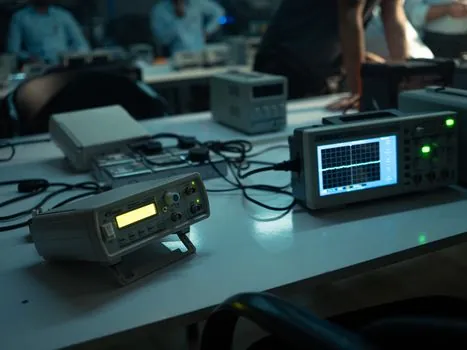
Wireless clamp-on CTs with LoRaWAN uplinks are now a stocked product category rather than a custom build, with vendor families covering branch-circuit (CT10x) and three-phase (CT3xx) form factors aimed at retrofit machine monitoring without pulling cable [S3]. These units convert the secondary current internally, apply RMS aggregation, and transmit over LoRaWAN on license-free sub-GHz bands, which is attractive for OEM skid builders and brownfield plant additions where running new signal wiring back to a PLC cabinet is the dominant cost.
Where hardwired analog 4-20 mA loops are still preferred, for instance inside hazardous-area enclosures governed by ATEX 2014/34/EU and the IEC 60079 series for explosive atmospheres, the CT loop itself stays in the safe zone and only the powered transmitter head enters the classified area through appropriate intrinsically barriers. In non-hazardous machine-state work, the same wireless CT family sits alongside wired energy meters, and the choice comes down to whether the operator needs real-time closed-loop control (wired, sub-second) or periodic condition monitoring (wireless, minutes to hours) [S3].
Selection Criteria and Common Pitfalls
Five specs cover the majority of clamp CT failures: (1) primary current rating matched to at least 1.25 times the normal load, with saturation check at fault; (2) accuracy class appropriate to function (0.5 for revenue, 1 for sub-billing, 5P/10P/PX for protection, often the same CT in dual-rated form); (3) burden rating that exceeds the actual loop impedance including cable run; (4) frequency range that covers the harmonics produced by the connected load, especially for VFD-driven motors; (5) safety agency listing for the installation environment [S4][S5].
The most common field failure is saturating a CT at motor start: a direct-on-line motor draws 6 to 8 times full-load current at inrush for roughly 100 to 300 ms, and a CT sized only to full-load current will clip the peak, producing a flat-topped secondary waveform that misleads both protective relays and analytics. The second is reversed orientation: CTs are polarised, and an arrow or P1 marking on the case must point toward the source, otherwise the secondary phase is inverted and any derived direction-of-power or phase-rotation reading is wrong by 180 degrees. The third is DC offset: standard iron-core clamp CTs are AC-only, and any DC component on the primary (a frequent occurrence on half-controlled rectifier loads) shifts the operating point on the B-H curve and degrades accuracy until the DC decays. Where DC is present, a transducer with active flux compensation or a Hall-effect open-loop device is the correct tool rather than a passive CT [S4].
For plant engineers comparing options on a like-for-like basis: a 100 A AC split-core clamp CT in class 1 from a major instrument vendor typically lists for tens of USD and installs in under a minute; a class 0.5 metering-grade solid-core equivalent from the same vendor carries a 2 to 5 times price premium and requires panel re-work; a LoRaWAN three-phase clamp-on transmitter lists for a few hundred USD and removes the wiring cost entirely at the price of a higher measurement cadence [S3][S5].
Standards, Sourcing, and Documentation

IEC 61869-2 is the governing standard for current transformers used in metering and protection, superseding the older IEC 60044-1 family across most jurisdictions; it defines the accuracy classes 0.1 through 3 for measurement and 5P, 10P, PX, PXR for protection, plus the burden, accuracy-limit factor, and short-time current ratings that appear on every nameplate [S4]. For hazardous-area installs, the CT itself is usually simple apparatus and falls outside ATEX certification as long as it neither stores nor dissipates more than the threshold energy, but the connected transmitter head is governed by ATEX 2014/34/EU and the IEC 60079 series.
Useful practical references include the current transformer family overview for adjacent metering instrument selection, the eddy current tester entry for non-contact inspection of conductors and busbars in the same cabinets, and the dry-type transformer reference for the upstream transformer whose load current the CT will be watching. For motor-side specifics on CT accuracy class and protection-relay coordination, the 5P/10P/PX spec guide walks through the same IEC 61869-2 classes from a relay-application angle and is worth reading alongside this article.
Two trackable signals for the next six to twelve months: first, broader stocking of LoRaWAN three-phase clamp CTs at the 100 A and 200 A ranges (the CT3xx family is already publicly listed as of October 2026) and continued displacement of wired 4-20 mA transmitter loops in non-hazardous retrofits [S3]. Second, gradual migration of machine-state analytics from dedicated signal conditioners to the metering CT's onboard DSP, with RMS, harmonic, and slip-frequency sideband features exposed over Modbus or LoRaWAN as standard data points rather than computed downstream.