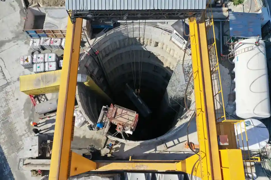
A diaphragm wall grab is a cable- or hydraulically-actuated clamshell tool that excavates a slurry-supported trench in 2.5–6 m wide panels, typically producing finished wall thicknesses between 600 mm and 1,500 mm [S1][S5].
The grab competes directly with hydraulic trench cutters (hydrofraises) and forms the second of two principal execution families described in the Bauer and BAUER equipment literature: the discontinuous "grabbed" method and the continuous "cut" method [S5][S6].
Where the Grab Excels: Mechanical Simplicity and Lower Capex
Grab rigs are widely used because the tooling itself is mechanically straightforward: a clamshell bucket is lowered into a bentonite-supported trench, closed to bite soil, and lifted to discharge spoil at surface [S2][S5]. On mechanical grabs the closing cable is reeved five to six times to multiply jaw closure force, while hydraulic grabs substitute a hydraulic cylinder for quieter, higher-force closure [S5].
This simplicity translates into three concrete advantages. First, capex and mobilisation cost sits well below a hydraulic cutter rig of equivalent depth rating, which is why grab systems remain the default for shallow-to-mid-depth urban basements [S4][S5]. Second, the panel system (U, T, L, I shapes) lets the contractor tailor panel geometry to ground conditions, depth, and equipment, with panel widths between 2.5 m and 6 m and individual "barts" sized to one grab bite (270 cm for a C800 grab, 250 cm for a B250) [S2]. Third, modern hydraulic grab variants such as the Kelly KRC2 HD and KHD systems add remote control, double rotary drive, and optional casing oscillators for steel-cased sections, expanding the soil range without leaving the grab family [S3].
Hard Limits: Depth, Rock, Verticality, and Spoil
Grab rigs lose decisively once ground conditions or depth exceed their mechanical envelope. Trench cutters are explicitly specified for depths beyond 40 m and for ultra-hard rock, where two counter-rotating cutter wheels crush strata and pump spoil continuously to surface [S5]. A grab, by contrast, transports spoil discontinuously and depends on chisels or modified grabs to break larger blocks, which caps practical depth and slows production in mixed-face conditions [S5].
Verticality is the second structural limit. Cutter rigs use hydraulic steering flaps and active weight control to regulate penetration, and onboard measuring systems on grabs only "verify" verticality rather than correct it, so deviation accumulates over depth [S5]. The third hard limit is spoil handling: slurry trenching generates large volumes of bentonite-contaminated mud, and the disposal of that waste mud in city construction is repeatedly flagged as a cost and logistics penalty for diaphragm wall projects in general, and therefore for grab jobs in particular [S7].
Decision Map: Grab vs Cutter vs Kelly/Hydraulic Hybrid
Selection on a real project comes down to four criteria: target depth, ground hardness, verticality tolerance, and unit-cost-per-m². Below 30 m in soft-to-medium cohesive or granular soil, the grab is the lower-cost option and remains the workhorse; beyond 40 m, or in rock stronger than what chisels can break, the cutter is the only practical choice [S5][S6]. For mixed urban profiles with intermittent obstructions (old foundations, boulders) and tight noise or vibration limits, modern hydraulic or Kelly-type grabs sit between the two, offering higher closure force and remote operation at a cost premium over a cable grab but well below a full hydrofraise spread [S3].
On vibration and noise, the comparison is also clear: mechanical grabs with reeved cables are the loudest option, hydraulic grabs drop noise and vibration significantly, and cutter rigs sit at the quiet end of the spectrum, which matters on hospital, transit, and inner-city sites [S5]. For contractors comparing lifecycle numbers on adjacent plant, the same capex-vs-depth logic shows up in the lifting-equipment world; see the crawler crane vs overhead bridge crane selection map for a parallel capacity-versus-cycle trade-off. Cost-band reasoning on a different asset class is laid out in overhead bridge crane TCO and 20-year lifecycle math, useful when a diaphragm wall package shares a site with heavy lift plant.
What the Grab Buys You in Wall Performance
Once the trench is complete, the wall itself inherits advantages that are independent of the excavation tool: high stiffness and structural integrity, near-seamless construction that gives strong waterproofing below the water table, vertical geometry that saves site footprint in dense urban plots, and long service life that reduces maintenance exposure [S1][S4]. Diaphragm walls also enable top-down basement construction, where the permanent wall doubles as the perimeter of the underground structure, eliminating temporary propping in many cases [S1][S5].
For deep, load-bearing soil layers, panels can be designed as "Barrettes", foundation elements that carry concentrated structural load in the same manner as large-diameter bored piles, a configuration the grab method supports as readily as the cutter method [S5]. The trade-off is build time: the grab cycle (excavate, lift, discharge, reset) is slower per cubic metre than a continuous cutter in hard ground, which extends programme on deep urban basements [S4][S5].
Cost, Schedule, and Site Footprint in Practice
Three cost lines dominate a grab-based diaphragm wall package: specialised plant mobilisation, skilled operating labour, and slurry plant setup including mixer, hydration tanks, and desanding units [S4][S5]. A congested urban site compounds these costs because the work area needed for slurry plant and rebar cage prefabrication is non-trivial, and pre-trenching plus guide wall construction must precede the grab itself [S5].
Guide walls are typically reinforced concrete with the top at least 4 ft above the groundwater table to allow dry working conditions during the panel pour, a small but non-negotiable detail in the sequence [S5]. Once excavation reaches panel depth, bentonite suspension is displaced by tremie-placed concrete whose higher specific gravity forces the slurry to rise and be recovered for reuse, which both controls waste volume and stabilises the freshly placed concrete [S2]. Adjacent deep-excavation projects in the same cost band, such as a backhoe loader selection logic in 2026, face the same mobilisation-versus-utilisation balance that a grab rig does on a tight urban plot.
Standards, QA, and Trackable Signals
Verticality on grab jobs is monitored with onboard inclinometer systems that compare real-time tool attitude against design tolerance, and on mechanically critical panels the contractor will typically run a sonic cross-hole or coring check on the finished wall before excavation proceeds downward [S5]. Slurry QA covers bentonite density, viscosity, sand content, and pH against project specification, parameters that are set during plant commissioning and logged per panel; a grab programme usually generates more slurry QA data points than a cutter programme simply because the panel count and the slurry cycling events are higher per linear metre of wall.
For specification engineers, three signals are worth tracking on a grab-based project: the measured verticality deviation logged panel-by-panel against the design envelope, the slurry recovery and reuse ratio reported by the desander, and the as-built wall thickness against the 600–1,500 mm grab range [S5]. Trends on those three numbers, more than headline unit-rate benchmarks, predict whether a grab package will hold programme and budget to completion. For further reading on the broader equipment category that includes grab rigs, trench cutters, and their support plant, see the construction machinery and equipment overview.
Detailed specification references: diaphragm wall grab, and diaphragm pump.