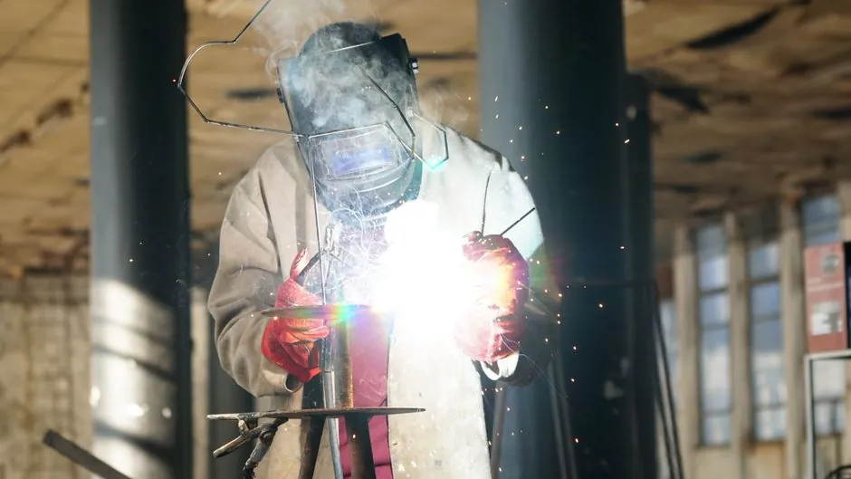
An electroslag pressure welder installation for vertical rebar on cast-in-place bridge columns runs on a 380 V three-phase supply, accepts bar diameters from 16 mm to 40 mm, and uses a controlled sequence of arc, electroslag, and upset stages inside a flux-filled mold [S1][S2].
The same equipment family, in its plate-welding ESW variant, is restricted on US fracture-critical bridge members under FHWA Notice N 5040.23 dated 1977-02-16, which removed the process from main tension members after brittle fractures on an I-79 plate girder [S3]. For procurement and inspection in 2026, the spec must be locked against the rebar code path (JGJ 18-2012 in China, AWS D1.4/D1.4M in the US) before the welding head is ordered, not after the bars arrive on site [S3].
Process Definition and What an EPW Installation Actually Delivers
Electroslag pressure welding (EPW) for rebar and electroslag welding (ESW) for plate both pass current through a conductive molten flux bath, but only the rebar process applies axial upset pressure to forge a bar-to-bar joint inside the slag pool [S3]. The slag pool in EPW reaches 1500-2000 degrees Celsius, melting the bar ends and a thin layer of adjacent base metal into a thermoplastic state before the upper bar is forced downward, squeezing molten metal and slag out of the joint to form a visible weld collar [S1].
On the plate side, the consumable-nozzle ESW process per GOST 30482-97 specifies electrode wire feed rates of 65-480 m/h, welding travel speeds of 0.15-9.0 m/h, and water-cooled copper slides to shape the outer weld surface, with the standard's introduction date 2002-01-01 still governing the CIS acceptance path [S4]. The practical installation envelope for rebar EPW is vertical or near-vertical bars within roughly a 4:1 gradient, diameters 16-40 mm, no separate filler wire, and a single ground clamp per bar pair [S3].
Selection Criteria: Power Source, Welding Head, and Upset Force
Four specifications drive the purchase decision for a 2026 rebar EPW installation: maximum bar diameter the welding head accepts (commonly 16, 20, 25, 32, 40 mm), welding current rating and duty cycle of the power source, the axial upset force the head can deliver, and the control sequencing of the three welding stages [S3]. The published ZX7-630 inverter specification lists welding current range 200-650 A, arc-process welding voltage 35-45 V U2, rebar diameter range 16-32 mm, and 380 V supply, with FOB/CFR/CIF trade terms out of Qingdao [S2].
For taller pier columns where the operator climbs with the head, an inverter DC welder with a programmable arc-to-upset timer (16-40 mm range) gives more repeatable weld collars than a manual AC transformer unit, at higher first cost [S3]. For large-diameter bars above 32 mm up to roughly 50 mm, a semi-automatic dual-operator rig with hydraulic upset gives the best collar consistency, but it weighs more and needs a crane lift to the deck [S3]. The weld-collar quality limits in JGJ 18-2012, covering axial offset, bar diameter mismatch, and visible defect thresholds, must be hittable under production rate, not just on a single lab coupon [S3].
Who Should Use EPW, and Who Should Not
EPW is the right tool for vertical column rebar in cast-in-place concrete piers, abutment stems, and retaining walls where bars run true and the crew can stage the flux box and welding head on a working platform [S3]. It is also a fit for high-rise vertical rebar splicing on building cores, where the speed of a single 30-40 second cycle beats manual electric-arc lap welding in both labor and material cost [S1].
EPW is the wrong tool for horizontal rebar splices, for bar diameters below 16 mm where the slag pool cannot establish reliably, and for any joint where the bars cannot be aligned within the axial offset tolerance JGJ 18-2012 sets for visual collar acceptance [S3]. Plate ESW in 2026 should not be specified for fracture-critical bridge members in the US, and on non-fracture-critical tension members the NGI-ESW variant (roughly 19 mm gap, no electrode oscillation, fixed travel-speed control) is the only form most AASHTO zone 1 and zone 2 owners will accept [S3].
Side-by-Side Comparison of Welder Classes for Site Installation
A procurement-grade comparison of the three rebar EPW classes that show up on a 2026 bridge bid, lined up against the four decision criteria a site engineer cares about, runs as follows [S2][S3]:
Manual clamp, AC transformer welder, 16-32 mm range, current 200-650 A class: lowest purchase cost, lightest head at the cost of operator-dependent weld collars, and only viable on small pier columns where the crew can rework a bad collar. Manual clamp, inverter DC welder, 16-40 mm range, programmable timer: roughly double the first cost, repeatable collars across shifts, and preferred on tall piers. Semi-automatic dual-operator rig with hydraulic upset, 25-50 mm range: best collar consistency on large-diameter bars, but heavier, needs crane lifts, and only pays back when the bar count is high enough to keep the hydraulic head loaded. For comparison with a related steel-plate bridge task, the oxy-fuel cutting torch selection for bridge construction guide covers the plate-prep side of the same workflow, since ESW splices usually need clean, square plate edges before the slag pool starts.
Site Installation Procedure: Six Verifiable Steps
Step 1, electrical: confirm a dedicated 380 V three-phase feeder with a properly sized breaker, route the welding head's control cable separately from the welding current cable, and verify grounding at the lower bar clamp per the inverter's IGBT-module manual [S1][S2]. The PUNAIR ZX7-630DH inverter spec sheet lists digital control plus a VRD (voltage-reducing device) anti-shock function, which is the feature an inspector will ask for on a wet rebar deck [S1].
Step 2, mechanical alignment: clamp the lower bar in the fixed chuck, set the upper bar in the movable chuck, and check axial offset against the JGJ 18-2012 collar limit before the flux box goes on [S3]. Step 3, flux loading: drop the specified welding flux around the bar ends to form the slag pool, and verify the lever- or screw-drive head is plumb within roughly 4:1 gradient [S1]. Step 4, arc initiation: trigger the welding head to strike the arc, hold the arc stage for the timer's preset, then let the current transition into the electroslag stage where the slag reaches 1500-2000 degrees C and melts the bar ends [S1]. Step 5, upset: the timer-driven handle or hydraulic ram forces the upper bar down, squeezing molten metal and slag out of the joint to form a convex weld collar, which the operator then visually inspects against the collar limits before the head is moved up to the next bar [S1][S3]. Step 6, inspection and test: per JGJ 18-2012 and AWS D1.4, sample splices go through bend tests and tensile tests, and the visible collar is checked for axial offset, bar-diameter mismatch, and surface defects, with any failed sample triggering a stop-work on that operator's head [S3].
Failure Modes, Acceptance Criteria, and When to Replace Rather Than Repair
The most common rebar EPW defects are incomplete fusion from an arc-stage overstay that burns the bar end before the slag pool establishes, off-center upset from misaligned chucks, and undercut at the collar root from too low an upset force [S3]. On the plate side, the documented failure path is brittle fracture initiating at an ESW weld repair in a fracture-critical member, which is why FHWA Notice N 5040.23 banned ESW on main tension members on 1977-02-16 and why the NGI-ESW refinement is the only plate variant a 2026 US bridge owner will accept on a non-FCM tension member [S3].
Acceptance values for rebar EPW are set by the collar limits and the bend/tensile test pass criteria in JGJ 18-2012 and AWS D1.4, not by a generic visual standard, and any splice that fails the bend test is cut out and rebar-coupled rather than re-welded [S3]. For a deeper dive on the bar-end prep side of the same workflow, the oxy-fuel cutting torch selection for plumbing installation guide covers the torch-seat-thickness logic that determines whether a square-cut rebar end can even feed a slag pool without arcing off-axis. GOST 30482-97 supplies the CIS-side weld-quality control methods and surface-roughness references (GOST 2789-73) that an EAC-region inspector will check on plate ESW, with the standard's date of introduction 2002-01-01 still in force as of the 2026-09-04 cutoff [S4].
Standards, Sourcing, and Trackable Signals for 2026

Three standards govern a 2026 EPW installation depending on geography: JGJ 18-2012 in China, AWS D1.4/D1.4M in the US, and GOST 30482-97 (introduction date 2002-01-01) in the CIS, while plate ESW in the US is governed by AWS D1.5 (Bridge Welding Code) and constrained on fracture-critical members by FHWA N 5040.23 (1977-02-16) [S3][S4]. For US plate work, the 2018-05-10 FHWA memorandum is the document that reopens NGI-ESW for non-FCM tension members in AASHTO temperature zones 1 and 2, and any spec that does not name it will be rejected at the owner's review [S3].
Two signals to track over the next procurement cycle: first, whether AWS D1.4M and JGJ 18-2012 publish any revision to the weld-collar visual limits, since the 2026 inverter-class welders now hit tighter timer windows than the legacy AC units; second, whether the FHWA 2018-05-10 memorandum is folded into the AASHTO LRFD Bridge Welding Specification text or stays as a stand-alone notice, because that change would shift which inspectors ask for the NGI-ESW travel-speed log on a given deck. The interaction between the welding head's linear guide rails, the cross-roller guide that aligns the upper and lower chucks, and the flux box position is detailed on the crossed roller guide encyclopedia page, and the basic power-source spec pattern is covered on the arc welder encyclopedia entry for teams that need to read an inverter nameplate against the JGJ 18-2012 current window. For a side-by-side read of how an EPW timer block compares to a stud welder controller on the same deck, the timer-stage logic is the cleanest spec level to audit first.