
Fettling grinders in pump and valve shops are matched to the casting or forging stage, not to a single brand: floorstand and swing-frame formats dominate iron casting cleaning, while bench and inline belt formats handle finished valve seats and stems.
The selection is driven by four gates: workpiece mass and swing radius, abrasive spec (wheel or belt), dust extraction class, and operator ergonomics. A fettling grinder formats reference clarifies the boundary between a foundry cleaning machine and a portable angle grinder used for trim work on the same shop floor.
Where Fettling Grinders Sit in Pump and Valve Production
Fettling is the post-cast cleaning step, separate from precision grinding of sealing surfaces. On a typical iron or stainless valve body, the sequence runs shot-blast or hand-dress, then fettling, then seat and stem grinding. Through-feed centerless grinding handles long uniform parts such as pump shafts, hydraulic rods, and valve stems where the entire length must be cylindrical to tight tolerance [S4].
For the body itself, a foundry floorstand or swing-frame machine carries a 300–600 mm abrasive wheel and removes 5–30 mm of stock per pass; for trim on assembled valve bonnets, an angle grinder with a 180–230 mm disc is the norm. Both jobs live on the same line, and conflating them is a common sourcing error.
Selection Criteria: Four Gates That Decide the Machine
Gate 1, workpiece mass and geometry. Floorstand and swing-frame units take castings up to 200 kg on a 1.2–1.8 m swing radius; bench units cap at roughly 30 kg and need a 600–900 mm wheel for general cleaning. Anything below 5 kg typically belongs on a pedestal or hand-held tool, not a dedicated fettling station [S1].
Gate 2, abrasive and stock removal. Aluminum-oxide wheels (A24–A36) handle iron and unalloyed steel valve bodies; silicon-carbide (C24–C36) is used on cast iron with high chill and on non-ferrous pump housings. Stock removal above 15 mm per pass needs a 5–7.5 kW drive and a reinforced wheel rated at least 80 m/s peripheral speed. For long stainless pump shafts and stems, through-feed centerless grinding delivers uniform diameter along the full length in one pass, while in-feed (plunge) is reserved for stepped or shouldered geometries [S4].
Gate 3, dust extraction. Iron and silica-bearing dust mandates LEV integrated to the wheel guard; stainless grinding on nickel-bearing alloys adds the requirement to capture fine particulates to keep operator exposure inside the respirable crystalline silica control band.
Gate 4, ergonomics and throughput. Vibration-damped handles, two-handed controls with brake, and a clearance height matched to the operator (typically 850–1050 mm) are the standard ergonomic checkpoints. A fettling grinder spec map covers the same gates across the five main formats and is a useful cross-reference when more than one format is in scope.
Comparison of Main Fettling Formats for Pump and Valve Work
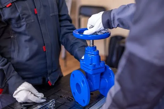
Five formats compete for the same cleaning slot. The table lines them up against the four selection gates so a buyer can see the trade in one glance.
Floorstand grinder. Best for 10–80 kg valve body castings. Typical 3–5.5 kW, 400–600 mm wheel, full LEV. Limitation: fixed work height, not ideal for tall pump casings.
Swing-frame grinder. Best for 50–200 kg pump housings on a floor pit. Long-reach arm (1.5–2.0 m) and 5–7.5 kW drive. Limitation: heavy, needs a fixed pit or turntable.
Bench/pedestal grinder. Best for trim, deburr, and small valve trim (under 30 kg). 1.5–3 kW, 200–350 mm wheel. Limitation: low stock removal, not a casting cleaner.
Inline belt/sander grinder. Best for flat sealing faces and stem flats. 2.5–4 kW, 100–200 mm belt width. Limitation: not suited to deep cavities on valve bonnets.
Portable angle grinder. Best for in-situ dressing on welded pump frames and large valve assemblies. 1.0–2.6 kW, 180–230 mm disc. Limitation: not a precision tool, depends on operator skill.
Standards, Sourcing, and What the Supplier Should Provide
A fettling grinder for pump and valve work falls under machine-tool safety (the EN ISO 16089 family for stationary grinding machines, with the applicable part for floor and bench units), and abrasive product standards cover the wheels. Dust extraction performance is normally specified to a class on the unit, and a vendor datasheet should show airflow in m^3/h and capture velocity at the guard, not just a "dust port" diameter. [S3]
Documented checks during sourcing: wheel speed certificate (peripheral m/s versus nameplate), guard impact test record, brake time for two-handed control (typically under 1 s for a 400 mm wheel), noise emission (dB(A) under load), and vibration total value at the handle per EN ISO 5349. Without these, a quote is incomplete. For pump and valve buyers also weighing related tooling, a sand blasting machine cost reference pairs naturally because shot-blast often sits immediately upstream of the fettling step on the same casting line.
Limitations and Failure Modes to Plan Around
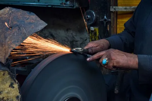
Wheel breakage from overspeed is the headline risk; the wheel nameplate, the spindle, and the ambient rating must agree. A 400 mm wheel rated 80 m/s on a machine that actually delivers 90 m/s at the rim will fail. The 403 error on the [S2] page in this research is a useful reminder that maintenance-process guidance, like wheel dressing and lubrication intervals, is easy to find in print but worth verifying against the current OEM manual before any grinding-line change.
Grinder vibration loosens set screws, slides, and adjustable stops over time, which is why regular dial-in checks and lubrication are mandatory, not optional, on a valve grinding station used for production [S2]. On the casting side, undersized dust extraction pushes the shop over its exposure limit within a shift; oversize dust extraction steals CFM from the welding bay next door. Sizing to the actual wheel diameter, hood geometry, and duct length is the fix. Pump and valve plants that ignore these three failure modes see wheel change intervals collapse from months to weeks.
Verdict: Match the Format to the Casting, Not the Brochure
For a pump housing or valve body foundry, start with a swing-frame or floorstand fettling grinder sized to the heaviest part, add LEV rated to the dust class, and confirm wheel speed, brake time, and vibration data on the datasheet. For trim and seat work, a bench grinder or inline belt sander is the correct machine, not a heavier foundry unit. For in-situ dressing on welded pump skids, a portable angle grinder is the right tool. Stepped or shouldered valve stems and shafts belong on in-feed centerless grinding, not through-feed [S4]. Cross-check any format choice against the broader construction machinery and equipment spec map when the fettling station sits inside a larger fabrication cell.
Trackable signals: vendor datasheets listing peripheral wheel speed, brake time under 1 s, and EN ISO 5349 vibration values at the handle; supplier audit reports on dust capture velocity at the guard; wheel-change interval trend by format over a 90-day window.