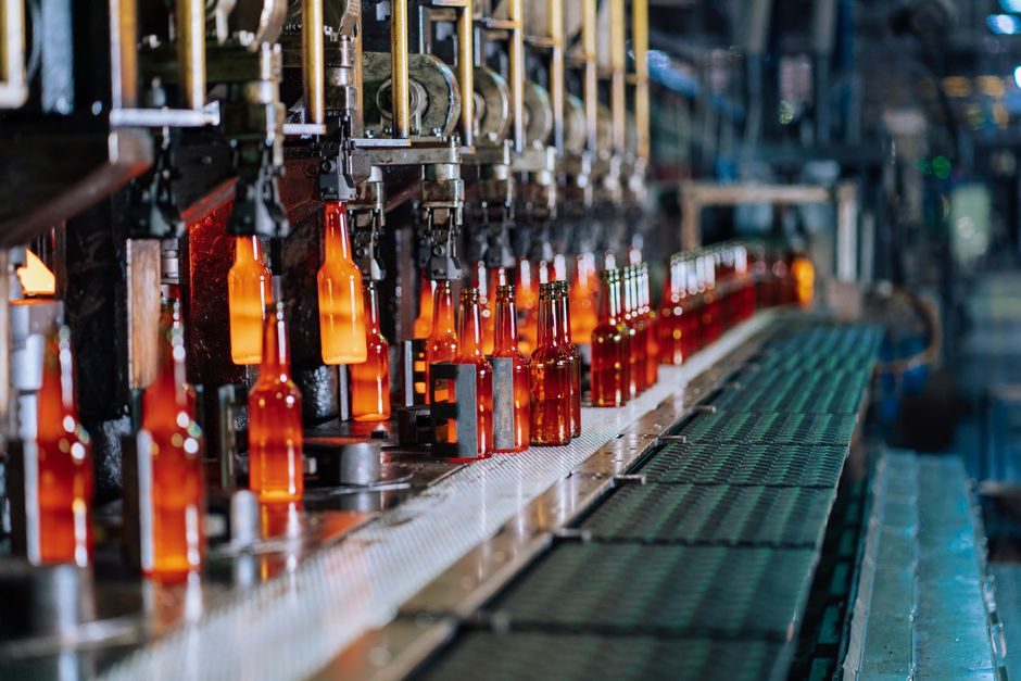
Industrial refrigeration covers refrigeration systems from 10 kW to 10 MW of cooling capacity, with evaporation temperatures from -50°C to +20°C, sized for plants where a cooling failure would jeopardize operations [S2]. The equipment chain always combines a compressor, a heat exchanger network, an expansion device (throttle or expander), and the refrigerant circuit; below -100°C the cycle is classified as cryogenic and effectively becomes a gas-liquefaction process [S1].
Process refrigeration is most common in natural-gas processing, petroleum refining, petrochemicals, and chemical manufacturing, where the goal is condensing or cooling vapors, gases, or liquids at well-defined temperature levels [S2]. Manufacturer reference works such as the Industrial Refrigeration Handbook organise the technology around the vapour-compression cycle and its component selection, with screw-compressor design (built volume ratio Vi, capacity control) covered in detail for ammonia chillers [S3].
Refrigeration Cycle and Process Block Diagram
A vapour-compression industrial refrigeration loop is built from four functional blocks: compression, condensation, expansion, and evaporation, with the working fluid circulating through brazed-plate, shell-and-tube, or evaporative heat exchangers depending on duty [S3]. Mechanical cooling down to about -210°C is achieved by throttling or adiabatic expansion; temperatures below 1 K require adiabatic demagnetisation, which sits outside normal industrial process refrigeration [S1].
Capacity is normally rated in kilowatts of refrigerating effect, and industrial systems scale from roughly 10 kW up to 10 MW per train, with multiple trains paralleled for larger plants such as LNG pre-cooling and ethylene plants [S2]. Process integration typically pulls heat from a process stream at a defined temperature and rejects it via a water-cooled or evaporative condenser, with the suction superheat set by the evaporator outlet to protect the compressor.
A useful baseline comparison of the three building blocks in a typical plant:
Compressor: piston (1-1500 m³/h suction), screw (100-10,000 m³/h), or scroll (1-50 m³/h) [S2]; Condenser: water-cooled shell-and-tube or adiabatic/evaporative; Expansion: thermostatic or electronic expansion valve, or expander for high-pressure-ratio duties [S1]. Sizing logic, in turn, follows the same pattern engineers use when mapping compressed-air system blocks and machine types for utilities, with flow, pressure ratio, and load profile as the three input variables.
Compressor Family and Capacity Map
Reciprocating (piston), screw, and scroll compressors dominate the industrial refrigeration market, with suction swept volumes from 1 m³/h up to 10,000 m³/h and direct drive from 2-pole (2950 rpm at 50 Hz), 4-pole (1450 rpm), or 6-pole (975 rpm) motors [S2]. Semi-hermetic construction is standard for small to medium units, while larger ammonia and hydrocarbon plants use open compressors with separate drive trains and VFD speed control.
Reciprocating compressors cover small to medium duties with good part-load turndown; screw compressors, both oil-flooded and oil-free, handle the 200 kW to 10 MW range and dominate ammonia liquid-chiller applications thanks to Vi (built volume ratio) matching and stepless capacity slide-valve control [S3]. Scroll compressors are largely confined to small commercial chillers and HC/HFC packaged units, with a growing role for oil-flooded scroll designs in medium duties [S2].
Recent development is moving away from incremental refinement toward new architectures: rotary spool machines, eccentric-casing rotary vane units, and torsional free-piston designs have all been prototyped in the last decade, and permanent-magnet motors are now being applied to swing and screw compressors for higher part-load efficiency [S2]. This is functionally similar to the way smart hydraulic cylinder manufacturing adds sensors and PM routines to legacy motion hardware; the refrigeration block diagram is being upgraded with VFDs, permanent-magnet drives, and oil-management instrumentation rather than re-invented from scratch.
Refrigerant Selection: Ammonia, CO2, HFCs, and Hydrocarbons
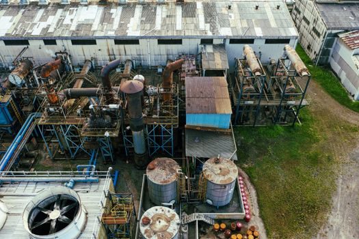
Refrigerant choice is dictated by capacity band, safety class, and process temperature: ammonia (R-717) is preferred in medium and large systems, CO2 (R-744) in small to medium systems, hydrocarbons (R-290 propane, R-1270 propylene) in small systems, and HFCs in legacy and medium duties where flammability rules restrict ammonia [S2]. The phase-down of chlorinated hydrocarbons (CFC/HCFC) has driven most of the last twenty years of compressor R&D and remains the primary regulatory pressure on plant designers [S2].
Decision matrix that designers actually apply:
Capacity under 50 kW: hydrocarbons or HFCs in packaged units [S2]; 50 kW to 2 MW: CO2 in cascade or transcritical, ammonia where local codes allow; 2 MW to 10 MW: ammonia dominates, with screw or large reciprocating compressors; Below -50°C evaporation: cascade with CO2 low stage, or mixed-refrigerant LNG designs, shifting into cryogenic equipment [S1][S2]. Process safety files, leak detection, and machinery-room ventilation scale with the refrigerant's flammability and toxicity class, so ammonia plants often drive higher mechanical-integrity spend than equivalent HFC plants of the same capacity.
Standards anchoring the duty: ASHRAE 15 (Safety Standard for Refrigeration Systems) classifies refrigerant safety groups and sets machinery-room requirements; EN 378 covers the same scope in Europe; pressure-vessel compliance falls under ASME BPVC Section VIII or PED 2014/68/EU depending on jurisdiction. Material and design selections are paired to refrigerant: ammonia service typically uses carbon steel with copper-free bearing alloys, while CO2 service above 30 bar demands stainless or heavy-wall carbon steel to stay inside the corrosion and toughness envelope.
Heat Exchanger Network and Process Integration
Evaporators and condensers in industrial refrigeration are selected against the refrigerant's pressure-temperature curve and the process-side fluid's fouling factor, with brazed-plate heat exchangers common for HFC/CO2 duties and shell-and-tube units for ammonia and high-load gas cooling [S3]. For process cooling, kettle-type evaporators and direct-expansion shell-and-coil vessels remain common where the refrigerant must be isolated from a fouling or hazardous process stream; for chilling secondary glycol or brine, plate heat exchangers dominate new builds because of their higher U-values per unit volume.
Process integration is the part that determines real plant efficiency: a single -35°C ammonia loop can serve food freezing, cold-room storage, and a process chiller simultaneously, with floating condensing-pressure control chasing ambient conditions to lift COP. In petrochemical service, refrigeration often ties to gas processing - de-methaniser overheads, ethylene cracker fractionation, and LPG recovery - where the evaporator acts as a partial condenser for the process column, as covered in standard chemical-engineering refrigeration chapters [S2].
Where plants need controlled cool-down of cryogenic piping and vessels, liquid nitrogen or expander-based cryogenic systems step in below the -100°C line, and the equipment chain reverts to liquefaction hardware (expander, cold box, mole-sieve pre-purification) rather than standard vapour-compression chillers [S1]. This is also where the manufacturing supply chain overlaps with induction furnace pros and cons on the metallurgical side, because austenitic stainless components for cold boxes and the steel envelope of screw compressors share a common material spec family.
Capacity Sizing, Efficiency, and Load Matching

Industrial refrigeration is sized by the sum of process loads plus a safety margin, with typical specific values of 0.25-0.50 kW per kW of attached process duty for chillers and 0.10-0.20 kW per kW for cold-storage applications [S3]. Coefficient of performance for single-stage ammonia plants typically runs 2.0-3.5 at -35°C/-10°C (evap/cond), and a two-stage screw plant with economiser can reach 3.0-4.5; CO2 cascade low stages operate below COP 2.0 because of the temperature lift but recover cascade heat at the high-stage condenser [S2].
Variable-speed drives on screw and permanent-magnet motors on scroll/swing compressors have become the default efficiency play, replacing cylinder unloading and slide-valve throttling for part-load control, and they can lift integrated part-load efficiency (IPLV) by 15-25% versus fixed-speed baseline [S2]. For food, dairy, and pharma plants with strong seasonal swings, this VFD layer often determines the payback of a refrigeration retrofit, particularly where the plant is tied to a time-of-use electricity tariff.
Plant-level selection logic, in summary, is: size the largest single load, pick the compressor family that matches the capacity band and refrigerant rules, pick the heat exchanger topology that matches fouling and pressure drop, and layer VFDs and economisers to chase the part-load efficiency target. Engineers approaching a new build will use the same fit-map logic as for utility equipment selection in smart pneumatic actuator valve automation - data-driven sizing against an explicit process duty, not a nameplate comparison.
Manufacturing Process, Standards, and 2026 Watch List
Industrial refrigeration units are manufactured as factory-packaged skids for small HFC/HC systems and as field-erected assemblies for ammonia and large screw plants; the build process follows the same quality gates as pressure equipment - material certificates to EN 10204 3.1, weld procedures to ASME IX or EN ISO 15614, and pressure testing per ASME BPVC Section VIII or PED 2014/68/EU. Compressor OEMs (Vilter, Frick, Mycom, Bitzer, Howden) publish full dimensional and performance data sheets, and the Industrial Refrigeration Handbook remains the most cited desk reference for screw-compressor Vi selection and capacity-control logic [S3].
Process engineers specifying new equipment in 2026 should pin refrigerant class, capacity band, and efficiency target before selecting a compressor family - the rest of the train, from heat exchangers to controls, follows from those three numbers [S2].
For the relevant spec sheets and selection criteria, see additive manufacturing material, multifunction process calibrator, and v process line.
