
Inverter-based stud welding power units cut weight by 50-70% versus transformer-rectifier designs and offer real-time arc parameter adjustment, while transformer-rectifier units retain a 50+ year service life advantage in heavy industrial settings [S1][S2].
The two architectures share the same job, stepping mains voltage down to the 17-45 V, 200-600 A arc-welding band, but they reach that band through different magnetic and switching topologies, which drives every downstream spec difference [S2].
Topology: Why a Transformer Lives Inside Both
Every stud welding power unit, inverter or transformer-rectifier, contains a step-down transformer; the difference is what sits around it [S2]. A transformer-rectifier unit uses a 50/60 Hz mains-frequency core with a diode bridge on the secondary, giving an AC or rectified DC output, typically 200-600 A at 17-45 V [S2].
An inverter unit first rectifies the mains to DC, then chops it at high frequency (commonly 20-100 kHz) before feeding a much smaller ferrite transformer, which then rectifies again to DC for the weld [S1][S2]. Higher frequency means smaller magnetic core, which is the entire reason an inverter stud welder head can be lifted by one operator instead of requiring a hoist [S1].
Weight, Footprint, and Site Handling
Transformer-rectifier stud welding power units are defined by heavy copper windings on a laminated silicon-steel core; practical units of 800-2000 A capacity weigh 150-400 kg and usually need mechanical handling for positioning [S1][S2].
High-frequency inverter units with comparable output rating drop the transformer mass by roughly two-thirds; Taylor Studwelding's i12 and i16 drawn-arc models and CDi capacitor-discharge range are specified as one- or two-person liftable for site work [S1]. In a fabrication yard or on a steel-frame construction site, that weight delta alone changes how often the unit is repositioned during a shift.
Electrical Efficiency and Input Power Quality
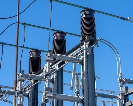
Inverter stud welders draw measurably less input current for the same weld energy because the high-frequency transformer core has lower iron and copper losses than a 50/60 Hz core of equivalent rating [S1][S2]. Forum field reports on marginal power supplies confirm that an inverter arc stays more stable than a transformer arc when the feeder is weak, which is consistent with tighter closed-loop current control on the IGBT stage [S3].
Where an inverter is paired with a variable frequency drive input stage or generator with poor voltage regulation, the welding cutting tool inverter's fast feedback loop still tracks the weld setpoint, but on a true 50/60 Hz transformer-rectifier the same sag shows up as arc wander [S3]. Three-phase transformer-rectifier units, however, are noticeably smoother than single-phase because three-phase rectification removes the 50 Hz ripple that gives single-phase stick welders their characteristic "choppy" feel [S5].
Duty Cycle, Heat, and Continuous-Production Throughput
Duty cycle is where the inverter architecture scores its second decisive win: high-frequency switching wastes less energy as heat, so the same cooling package sustains a higher output for longer [S1][S2]. Taylor Studwelding's drawn-arc i-series spec sheets advertise a higher duty cycle at rated current than legacy transformer-rectifier units of comparable output [S1].
For a stud-welding cell running M12-M16 shear connectors on composite floor decks at 30-40 studs per hour, a higher duty cycle means fewer thermal cutouts and less waiting on the gun cooling. A 50-year-old transformer-rectifier will still weld, but it spends more of its shift derated, or simply idled while the contactor cools [S2][S3].
Weld Quality: Arc Stability, Spatter, and Parameter Control
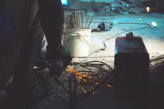
Inverter units offer closed-loop control of weld current, weld time, and lift on a cycle-by-cycle basis, typically at 1-2 ms resolution, which reduces spatter and under-fill on drawn-arc studs and gives cleaner fillet formation on CD welds [S1]. Transformer-rectifier units rely on tap-switch or saturable-reactor current control with coarser steps, and their arc is more sensitive to stud-to-base surface condition.
For shear-connector welding to AWS D1.1 or equivalent structural codes, the parameter repeatability of an inverter translates directly into fewer destructive-test failures, the kind of metric a process engineer will see in a QA log. Independent practitioner reports consistently rank inverter arc stability ahead of transformer-rectifier, with the qualifier that the difference narrows when both units are fed from a stiff three-phase supply [S3][S5].
Reliability, Service Life, and Field Repair
Transformer-rectifier stud welders routinely reach 30-50+ year service lives with nothing more than contactor and diode replacement; that longevity is well documented in heavy-industry shop experience [S2][S3]. Inverter units are more compact but pack IGBT modules, gate drivers, and DSP control boards whose repair cost is higher and whose field serviceability is lower; a control-board swap can cost 30-50% of a new entry-level unit [S2][S3].
For a steel-fabrication shop running two shifts, the lifetime math comes down to hours per week. A shop that logs 20+ hours of arc time weekly will amortize an inverter's higher purchase price and lower operating cost inside 2-3 years; a site that fires the stud welder a few times a month will keep a transformer-rectifier on the floor for a generation [S2][S3].
Decision Matrix: Which Architecture to Specify
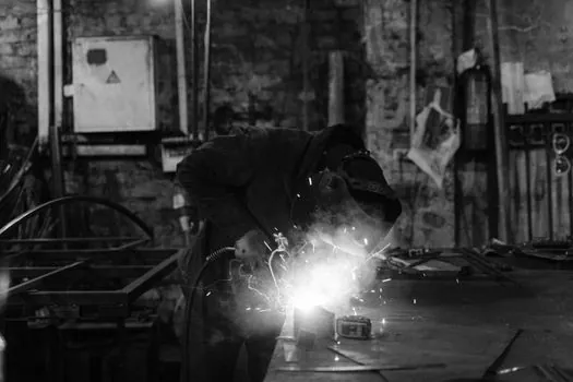
Use an inverter stud welder when the application is mobile site work, single-phase or generator supply, high duty cycle, or close-tolerance structural welding where parameter repeatability matters; expect 20-30% higher capital cost offset by 20-30% lower electricity use and 50-70% lower handling cost [S1][S2].
Use a transformer-rectifier unit when the unit lives in a fixed welding bay, three-phase power is available, hours-per-week are low, the operator skill level does not need arc-forgiving control firmware, and the buyer expects 30+ year service with a screwdriver and a multimeter [S2][S3]. For hybrid shops that weld both heavy structural studs and light CD fasteners, the CDi and drawn-arc inverter ranges from established OEMs have effectively closed the historical "transformer-only" gap on small-diameter work [S1].
Standards, Sourcing, and Selection Caveats
Stud welding power unit selection is governed by the AWS C5.4 / AWS D1.1 stud-welding provisions for structural applications, with CE/UKCA marking required for European sites; OEM datasheets for inverter models are the authoritative source for actual measured duty cycle at 40 deg C ambient, not marketing-cycle numbers [S1].
When evaluating an inverter unit, request the IGBT switching frequency, the I²t let-through of the input fuse (related to the inrush behaviour covered in sizing input fuses for high inrush I²t on power supplies), and the IP rating of the control enclosure; an IP23S rating is the practical minimum for indoor fabrication, IP54 for outdoor structural sites. Transformer-rectifier units in dusty shop environments benefit from a hydraulic power unit-style sealed cabinet if the OEM offers it. Two trackable signals to watch: IGBT-module prices continuing to fall, which keeps pushing inverter capital cost down, and a steady flow of 30-50 year-old transformer-rectifier units on the used market, a reminder that the older topology has not retired yet [S1][S2][S3].