
A 16 AWG 2-core stranded blue-jacket IS control cable (FLEX-IS-OZ type, PVC outer sheath, oil-resistant flexible construction) is the typical baseline product spec carried by North American and European stockists for hazardous-area loops [S3].
The light blue (RAL 5015) sheath is the field identifier for circuits wired to ATEX/IECEx "i" protection, and the same colour is reused as a permitted identifier in NEC Section 504.80(C) for Class I, II, III Division 1 installations, giving specifiers a single visual language across both regulatory regimes [S1][S2][S4].
Why the Jacket Is Blue, and Which Standard Says So
Under EN/IEC 60079-14, intrinsically safe and associated apparatus wiring must be clearly identified, and when colour is used for that identification, the colour must be light blue; this rule covers terminal-block housings, cable junction enclosures, and the cable jacket itself, and it applies across the same standard that governs the 50 mm (2 in) terminal separation distance from non-IS circuits [S5].
The RAL 5015 shade is the de-facto European reference, while the equivalent U.S. rule is NEC Section 504.80(C): in the NEC framework, light blue is a permitted means of identification, not a hard requirement, and Sections 504.80(A) and (B) still require that the IS components be identified by some other means if blue is not chosen [S4]. A May 2026 industry post states the IEC requirement as a "MUST" [S7]; in practice the IEC wording is a "shall" tied to "where colour is used", not a blanket ban on alternative identifiers, which is why some plants use permanent blue labelling on a non-blue cable for retrofit work [S4][S5].
Shielding Function, Not Decoration
Shielding in an IS cable serves two distinct jobs: rejecting external EMI on low-level instrument signals, and keeping the IS loop's capacitance, inductance, and L/R ratio inside the entity-concept budgets declared on the barrier and field-device datasheets [S2][S5].
Because the shield is a conductive path that can accidentally couple energy into the IS circuit if grounded at more than one point, IEC 60079-14 requires the shield to be covered by an additional insulating layer so that the only intentional ground is the single point specified on the control drawing; a drain wire with overall foil plus a tinned copper braid is the most common construction for an shielded cable carrying 4-20 mA + HART or PROFIBUS PA traffic in a Zone 1 or Class I Div 1 run [S5]. The capacitance per unit length figure on the cable datasheet (typically tens to low hundreds of pF/m) feeds directly into the entity calculation alongside barrier Ci, barrier Li, device Ci, and device Li, and any field substitution must keep the total C and L inside the barrier's allowed Ca and La at the declared Vmax and Imax [S2].
Comparison: Blue IS Cable vs Generic Instrument Cable vs Armoured IS Cable
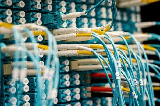
Three construction types dominate IS-circuit procurement, and the decision is driven by mechanical risk, zoning, and EMC, not by the IS concept itself, which only governs energy limitation [S2][S5].
Generic PVC control cable (e.g. a control cable with numbered black cores, no blue jacket): lowest cost, widely available, but no visual IS identification and no documented C/L for the entity calculation, so it is only acceptable when the designer relies on the "simple apparatus" clause and proves the loop with a separate assessment [S2]. Blue-jacket PVC IS cable, shielded, multi-conductor (typical 2 to 12 cores, 0.5 mm² to 2.5 mm², RAL 5015 sheath): the workhorse for Zone 1/Div 1 panel-to-transmitter runs, C and L printed on the datasheet, oil-resistant PVC or PUR jacket, and a foil+braid shield with an insulating inner layer [S1][S3][S9]. Armoured IS cable (SWA or STA, blue jacket retained under the armour): specified for direct-burial, outdoor, or high-mechanical-risk routes where a cable gland terminates the armour and the gland itself must be selected for the same Ex rating as the enclosure, often requiring a barrier-type or "Ex d" certified gland on Zone 1 boundaries [S5][S9].
For a standard 4-20 mA + HART transmitter loop inside a control room-adjacent Zone 1, the blue-jacket shielded PVC IS cable hits the lowest total installed cost; armoured blue-jacket IS cable becomes mandatory once the route leaves the building, runs on a cable tray shared with non-IS power, or climbs a hazardous-area structure subject to mechanical damage, with the armour gland rated for the same zone classification as the field device it lands on [S5][S9].
Selection Criteria That Drive the Part Number
Five spec values must be locked before ordering: (1) conductor size and count, (2) voltage rating, (3) operating temperature range, (4) datasheet C, L, and L/R per km, and (5) jacket material rated for the chemical and oil exposure of the route [S2][S3][S9].
Conductor sizes of 0.5 mm² (20 AWG) to 2.5 mm² (14 AWG) cover the bulk of 4-20 mA, HART, Foundation Fieldbus, and PROFIBUS PA loops, with 16 AWG 2-core stranded (30/30 stranding) constructions such as the FLEX-IS-OZ-OZ type listed as a stock SKU by multiple European-aligned distributors [S3]. Voltage rating for instrument IS cable is typically 300/500 V, well above any entity-loop Vmax; what actually limits the run is C/km and L/km, not voltage breakdown [S3][S9]. Jacket choice follows environment: PVC for general indoor and panel runs, PUR where repeated flex or aggressive oil is present, and LSZH (low-smoke zero-halogen) for occupied or marine spaces, with the blue RAL 5015 colour retained across all three jacket chemistries [S2][S9].
Installation Constraints That Decide Conduit, Tray, and Gland

IS wiring must be physically segregated from non-IS wiring: 50 mm (2 in) terminal-to-terminal separation inside panels, and either a grounded metal partition or a separate cable tray for the field run, with blue-jacket cable used as the visual cue that a tray segment is IS-only [S5].
Shield grounding is single-point only at the barrier or marshalling rack end unless the control drawing explicitly allows a multi-point scheme, which is unusual for entity-concept loops; mis-terminating the drain wire at both ends is a common commissioning fault that injects 50/60 Hz noise into low-level signals and can also create a ground loop that violates the entity calculation's assumption of a single reference [S2][S5]. Cable glands on field enclosures must be selected for the same zone as the enclosure, typically Ex e or Ex d, and on armoured IS cable the gland must bond the armour to the enclosure body while leaving the inner blue-jacket sheath and its insulating layer over the shield intact up to the gland face [S5][S9].
Real Use Cases and Where the Blue Jacket Is Not Enough
Oil and gas upstream wellhead panels, chemical plant DCS drops, pharmaceutical reactor bays, and grain-elevator weighing instrumentation are the four most common application families, and all four pair the blue-jacket IS cable with a Zener or galvanic barrier on the safe side of the loop [S2][S9].
The blue-jacket rule does not waive any of the other IS requirements: the loop still needs the entity calculation signed off, the barrier still needs to match the device's Ci+ Ccable ≤ Ca and Li+ Lcable ≤ La envelope, and the field device still needs its own Ex certificate for the zone in which it is installed, with cables treated as "simple apparatus" only when the entity parameters are documented end-to-end [S2][S5][S9]. In the U.S. a blue-jacket cable alone does not satisfy NEC 504.80(A) and (B) component-identification rules, so labels at every junction box and the matching barrier terminal are still mandatory on top of the jacket colour [S4].
Standards, Certifications, and Source-to-Data Map
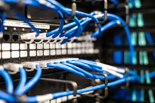
EN/IEC 60079-14 governs the installation rules referenced throughout (segregation distances, light-blue identification, shield isolation), ATEX 2014/34/EU and ATEX 1999/92/EC cover the EU equipment and worker-safety directives, IECEx is the international equivalent certification scheme, and UL 60079-11 / UL 913 plus CSA cover the North American IS system certifications, all cited in the 2026 ATEX selection guide for IS cables [S2][S5].
On the cable side, datasheet C (pF/m), L (µH/m), and L/R (µH/Ω) are the three numbers that determine whether a candidate part number fits the entity calculation, and these are typically printed on the manufacturer data sheet, e.g. for a HELUKABEL-branded blue-jacket shielded cable stocked as an IS control/connection cable line [S9] or a Lapp-style FLEX-IS-OZ PVC construction [S3].
The decision node a specifier can track next: confirm whether the loop runs in IEC 60079-14 territory (blue jacket is the "where colour is used" rule) or in NEC 504 territory (blue is permitted, identification is mandatory), and whether the cable gland selected for the field enclosure matches the same Ex protection type as the enclosure itself; getting either item wrong invalidates the entity concept on paper even when the blue-jacket control cable on the reel is the correct part number [S2][S4][S5][S9].
Related analysis: When to Specify AISI 9310 Instead of 8620 for Carburized Gears.