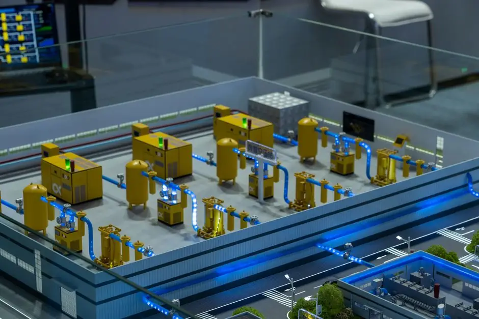
A machine vision system pairs industrial cameras, optics, structured lighting, and embedded or PC-based image processing to inspect hundreds to thousands of parts per minute, with throughput driven by sensor resolution, frame rate, and exposure control [S2].
Machine vision is the industrial subset of computer vision, optimised for factory duty cycles: deterministic latency, ruggedised enclosures, and integration with PLCs, robots, and MES layers [S3][S5]. Buyers evaluating a machine vision system in 2026 should anchor the spec on defect class, line speed, and communication protocol before comparing vendors.
Definition, Scope, and the Five Functional Blocks
Every machine vision system, regardless of form factor, is built from five functional blocks: image acquisition, image processing and recognition, result output, system control, and a display/HMI layer [S4]. The acquisition block combines camera, lens, and vision light source; the processing block executes algorithms on a smart-camera SoC, an industrial PC, or an FPGA; the result block delivers pass/fail, measurement values, or coordinates to a PLC over discrete I/O, Ethernet/IP, PROFINET, or OPC UA [S1][S4].
OPC UA for Machine Vision (companion specification OPC 40100-1) standardises the information model across these blocks with object types for VisionSystem, ConfigurationManagement, RecipeManagement, and ResultManagement, so a vision cell can publish structured results and accept recipe changes from a MES without custom drivers [S1]. For buyers, that standardisation is the single most important question to ask a vendor: which companion specifications and profiles does the system implement, and how are recipes and results exposed to higher-level systems.
1D, 2D, 3D, and Spectral: Picking the Sensor Class
Machine vision systems are categorised into four technology classes: 1D, 2D, 3D, and spectral or colour imaging, with the choice driven by what must be detected rather than by camera brand [S3]. A 1D system reads barcodes, lot codes, and continuous web defects at the highest line speeds; a 2D system handles pattern matching, OCR, and surface inspection; a 3D system delivers height maps via laser triangulation, structured light, or time-of-flight; a spectral system separates materials by reflectance or fluorescence [S2][S3].
Two specifications dominate image-sensor performance: resolution (pixel count) and sensitivity (minimum detectable illumination), and the trade-off between them is the central engineering decision in any build [S2]. High-resolution 2D area sensors (typically 5-20 MP) are standard for electronics and pharmaceutical packaging, where sub-millimetre features must be resolved; line-scan sensors with 2K-16K pixels per line are used for continuous webs (paper, film, metal strip) at line speeds above 10 m/s [S2]. For buyers, the rule of thumb is to size resolution to the smallest defect (at least 2-3 pixels across the feature) and frame rate to the line speed, then check that the sensor's global shutter prevents motion artefacts on moving parts [S2].
Smart Camera vs Multi-Sensor PC-Based System: When Each Wins
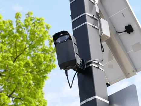
Vision systems split into two architectural classes: smart cameras (sensor, processor, lens, and I/O integrated in one housing) and PC-based or multi-sensor systems (separate cameras feeding an industrial PC or vision controller) [S6]. The decision is governed by cycle time, number of inspection points, and environmental sealing, not by software brand.
Comparison of the two options on four engineering criteria, drawn from the research materials:
Criterion 1: Cycle time. Smart cameras typically handle 10-100 inspections per second on simple pass/fail tasks; PC-based systems with multi-core CPUs or GPUs scale to multiple high-resolution cameras and complex AI inference at hundreds of inspections per second [S6][S7]. Criterion 2: Camera count. Smart cameras are deployed as standalone units (1 inspection point each); PC-based systems routinely run 4-8 cameras per controller using a GigE Vision, USB3 Vision, or CoaXPress frame grabber [S6]. Criterion 3: Environmental sealing. Smart cameras are IP67-rated as a unit and suit washdown or dusty cells; PC-based systems need a sealed enclosure for the controller and separate IP ratings for each camera head [S6]. Criterion 4: Software stack. Smart cameras run embedded firmware with a fixed toolset; PC-based systems run full vision software (Halcon, VisionPro, LabVIEW, OpenCV-based) with deeper scripting and AI model integration [S6][S7].
For a single inspection point on a conveyor, a smart camera from a vendor such as Keyence or Cognex is the lower-risk choice; for a multi-camera robotic cell or a high-speed web line, a PC-based architecture is the only viable path [S6][S7]. A practical shorthand: if the cell has fewer than 2 cameras and the cycle time exceeds 50 ms, stay with smart cameras; if either bound is broken, move to a PC-based vision controller [S6].
Lighting, Optics, and the Inspection Envelope
Lighting is the single most common cause of failed vision deployments, and the rule is to engineer the light first and the camera second [S2]. Common lighting geometries include backlight (for silhouette and dimensional measurement), ring light (for general 2D inspection), coaxial/dome light (for reflective or curved parts), and structured laser line (for 3D triangulation) [S2]. Buyers should request a lighting audit from the vendor: a documented photometric setup with measured lux at the part, exposure time, and lens aperture.
Optics selection is governed by sensor size, working distance, and field of view, using the standard equation: focal length equals sensor size times working distance divided by field of view [S2]. For 2/3" sensors (the most common in factory vision), focal lengths of 8-50 mm cover most cells; telecentric lenses are specified when measurement accuracy is independent of part position, which is the norm for metrology, but they cost 3-10x a standard lens and require very even illumination [S2]. Resolution of the optical system (in line pairs per millimetre) must exceed the sensor's pixel pitch, or the camera is wasting resolution on a soft image.
Selection Criteria: How Buyers Should Score a Vendor in 2026

A spec-first shortlist in 2026 should score each candidate system on six criteria, each grounded in a verifiable technical attribute. Selection criteria for machine vision systems include: sensor class and resolution matching the smallest defect to be detected; frame rate versus line speed with a documented margin; supported communication protocols such as OPC UA per OPC 40100-1; a lighting and optics ecosystem including off-the-shelf mounts and IP-rated housings; a software toolchain with AI/deep-learning add-ons and versioned recipe management per OPC 40100-1; and service and calibration support including on-site recalibration interval and traceability documentation.
The machine vision market in 2026 spans compact smart cameras (Cognex In-Sight 9000, Keyence CV-X/XG-X series, Sick InspectorP) for single-point inspection, and PC-based platforms (Cognex VisionPro, MVTec Halcon, National Instruments Vision Builder) for multi-camera cells [S7]. For buyers comparing hardware tiers and price bands, the industrial camera price and cost guide maps sensor class, frame rate, and protocol support to 2026 vendor tiers. For plants standardising on OPC UA across vision, motion, and process cells, the top industrial Ethernet companies 2026 vendor map covers the protocol-mix and market-sizing backdrop that a vision purchase sits inside.
Who Should NOT Buy the Mainstream 2D Smart Camera
The mainstream 2D smart camera is the wrong tool in three specific duty profiles, and the failure mode is consistent: missed defects, false rejects, or unstable measurements [S2][S6]. Duty 1: specular or curved surfaces under variable ambient light, where a 2D image cannot separate a scratch from a reflection; the right tool is a 3D line-scan profiler or a dome light with polarised filtering. Duty 2: high-speed continuous web (metal strip, paper, film) above 10 m/s, where area-scan smart cameras cannot keep up; the right tool is a line-scan camera on an encoder, mounted on a precision linear guide or crossed-roller guide for stable scanning. Duty 3: sub-pixel metrology to better than 5 micrometres, where a smart-camera lens and sensor stack cannot resolve the feature; the right tool is a telecentric-lens PC-based system with a calibrated vision measuring machine workflow [S2].
Buyers who default to a 2D smart camera on these duty profiles typically discover the limitation at the factory acceptance test, when the defect library produces unacceptably high false-reject rates, so the engineering review should explicitly score the system against the worst-case defect, not the typical defect [S2].
Standards, Sourcing, and Next Steps
The governing standards to verify during a 2026 procurement are: OPC UA companion specification OPC 40100-1 for vision information modelling, recipe management, and result publishing [S1]; GigE Vision, USB3 Vision, and CoaXPress for camera-to-controller transport; and ISO 9001 / IATF 16949 quality system coverage at the vendor, since vision systems used in regulated automotive, pharmaceutical, or medical-device lines must sit inside a controlled calibration chain [S1][S2]. Buyers should also ask for the EMVA 1288 sensor characterisation report, which gives quantum efficiency, dark noise, and saturation capacity independent of vendor marketing claims.
Two trackable signals for the next 6-12 months: the release of revised OPC UA for Machine Vision companion specification updates (recipe and result extensions, currently under working group review) [S1], and the integration of on-device AI accelerators (e.g. NVIDIA Jetson Orin, Hailo-8) into mid-tier smart cameras, which is shifting the cost-per-inspection-point down for embedded deep-learning classification. Buyers who have a 2026 capex window should request a side-by-side demo of a smart camera versus a PC-based system on their actual part, with defect libraries representative of their true production mix, before signing a multi-cell framework agreement.