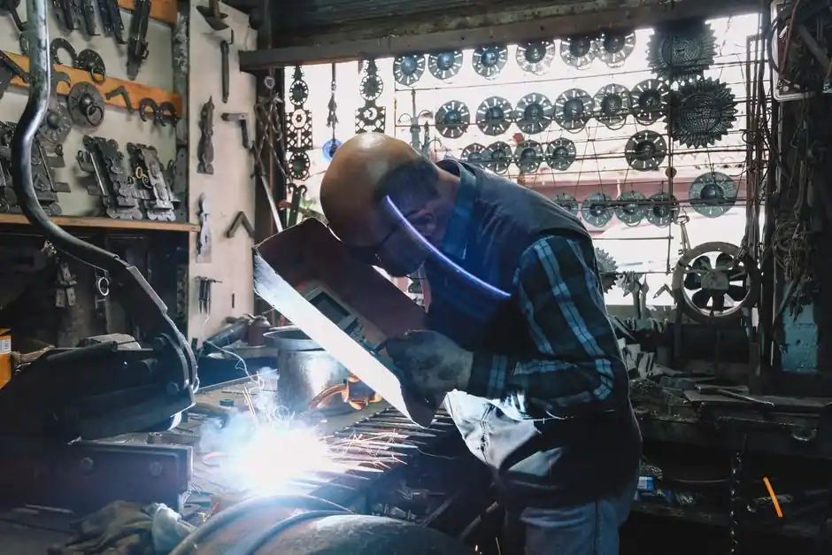
An arc welding power source is a current- or voltage-regulated electrical generator, and every commercial design (transformer, rectifier, transformer-rectifier, engine-driven generator, or inverter) reduces to the same four functional blocks: a mains/engine input and isolation stage, a transformation or high-frequency inversion stage, a rectification and smoothing stage, and an output regulation stage with current/voltage feedback.
Selecting between them is fundamentally a duty-cycle and process question: stick and TIG work from a constant-current (CC) source, while MIG, flux-cored, and submerged-arc work from a constant-voltage (CV) source, and the internal components change to match that control law [S1][S4].
Input, isolation, and EMC filtering stage
Every grid-powered welder starts with an input contactor or soft-charge circuit, a line filter for conducted EMC, and an isolation transformer or, in inverter designs, a high-frequency transformer that provides the galvanic separation between mains and the secondary welding circuit [S1][S2]. On transformer-rectifier and AC transformer sets, the mains frequency (50 Hz or 60 Hz) flows through a heavy laminated silicon-steel core; on inverter sets the mains is first rectified to DC and then chopped at 20 kHz to 100 kHz before the isolating transformer, which is why inverter cores can be 5 to 10 times smaller and lighter than transformer sets at the same output rating [S1][S2].
Engine-driven welders replace the mains input with a diesel or gasoline prime mover turning an AC generator, but the downstream rectification and regulation blocks are essentially the same as a grid-powered rectifier set [S4]. For sites subject to the EU EMC Directive or FCC Part 15, the input filter and proper PE bonding are non-negotiable; for shipboard and offshore builds the additional rules in IEEE 45 and the marine classification societies apply on top of the base insulation [S1].
Transformation or high-frequency inversion stage
Conventional transformer welders step the input down to a low-voltage, high-current secondary (typically 60 V to 80 V open-circuit) on a laminated iron core; AC transformer sets deliver this AC directly to the electrode, while AC/DC transformer-rectifier sets add a secondary rectifier stack [S1]. DC generator sets use a separately excited or compound-wound rotating machine whose field current sets the output.
Inverter welders replace the 50/60 Hz transformer with a DC-link plus an IGBT or MOSFET H-bridge switching at high frequency, a small ferrite transformer, and a secondary rectifier; the result is roughly 85 to 92 percent electrical efficiency versus 60 to 70 percent for a conventional transformer-rectifier at the same rated current [S2][S1]. For process engineers comparing the two, the arc welder power source design reference summarises how each topology trades weight, efficiency, and dynamic response, and why inverter designs have largely displaced transformer-rectifier sets in new CC/CV multi-process equipment below about 600 A [S1][S2].
Rectification, smoothing, and output stage
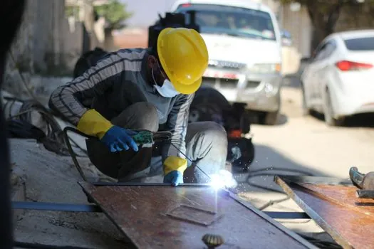
The output stage converts whatever the transformation stage produces into a usable welding waveform and smooths it. On AC sets, the output is the transformer secondary itself; on DC and AC/DC sets, a diode or thyristor bridge rectifies the secondary and an inductor-capacitor DC link filters it, holding open-circuit voltage in the 50 V to 80 V range typical of SMAW and the 14 V to 40 V working range of GMAW [S1][S3].
Engine-driven sets also pass the generator output through a mobile rectifier module, and modern inverter designs add IGBT output stages that can shape pulsed, AC square-wave (for aluminium GTAW), or waveform-controlled MIG output at frequencies up to about 500 Hz, which a 50/60 Hz transformer simply cannot produce [S1][S2]. The work lead and electrode lead terminate this stage at the stud or Dinse connector on the front panel; cable cross-section is sized to the rated current (for example, 50 mm² copper for a 350 A duty cycle at 60 percent) because voltage drop in the cables directly disturbs the regulation loop [S3][S5].
Regulation, feedback, and control board
The defining component of any modern power source is the feedback loop that holds either current (CC) or voltage (CV) constant against arc-length disturbances. In CC mode the current feedback is taken from a shunt or Hall-effect sensor and the setpoint is compared against the actual arc current to drive the output; in CV mode the same electronics compare arc voltage to setpoint and modulate output to compensate [S4].
Because arc length directly sets arc voltage and current sets heat input, a CC source tolerates the hand wobble of manual stick and TIG welding, while a CV source is mandatory for mechanised GMAW, FCAW, and SAW where the wire feed speed and the constant-voltage loop together hold arc length steady [S4]. Under normal stick arc length a CC source runs at roughly 20 V open-circuit, and the loop adjusts current to maintain penetration as the operator changes arc length [S4]. The setpoint, hot-start, arc-force, and inductance or slope controls are implemented on the same control board, with digital MIG front panels adding synergic tables that cross-reference wire type, diameter, and gas to a single one-knob current setting [S1][S5]. The same power source family is described in the welding cutting tool reference, which links the output regulation block to the downstream torch, wire feed, and gas circuit.
Selection criteria, comparison, and process fit

Process fit and duty cycle drive topology choice. Manual stick (SMAW) and GTAW want a CC source with good open-circuit voltage (around 60 V to 80 V) and adjustable arc force; GMAW, FCAW, and SAW want a CV source with a flat volt-amp curve, low output inductance, and the ability to parallel wire feeders; pulsed and AC TIG welding wants an inverter with a fast IGBT output stage [S1][S4][S5].
Compared on the four criteria that matter to a process engineer (efficiency, weight, dynamic response, and capability for advanced waveforms), conventional transformer-rectifier sets sit at 60 to 70 percent efficiency, the heaviest weight, the slowest response, and no advanced waveform; inverter sets sit at 85 to 92 percent efficiency, 30 to 50 percent of the weight, sub-millisecond response, and full support for pulsed MIG, AC TIG, and synergic one-knob control [S1][S2][S5]. A useful inline summary: a transformer-rectifier is still a defensible choice for a high-amperage SAW bay (600 A to 1500 A) where efficiency losses are dwarfed by arc-on time, but for a multi-process fab cell below about 600 A an inverter is the default in 2026 builds [S1][S5]. For power distribution planning, remember that an inverter at 90 percent efficiency still draws 30 to 40 percent less feeder current than a transformer set of the same nameplate, which directly shrinks the upstream breaker and cable sizing.
Limitations, failure modes, and sourcing standards
The two failure modes that hit every topology are overheating of the isolation transformer or IGBT heat sink, and contamination of the output rectifier or IGBT module by dust and coolant. Transformer-rectifier sets are tolerant of input undervoltage but heavy; inverter sets are intolerant of input undervoltage and poor cooling, and their IGBT modules fail catastrophically if the DC-link capacitor bank is not regularly inspected for capacitance loss [S1][S2].
Sourcing and standards: open-circuit voltage limits and operator safety are governed by IEC 60974-1 (arc welding equipment, Part 1: power sources), which caps CC open-circuit voltage at about 113 V DC or 113 V peak AC for operator-safety classes; reduced-voltage devices are required for environments with increased electric shock hazard such as wet or confined spaces [S1]. Process qualification on the welding side (not the power source itself) typically follows ISO 9606 for operator qualification and ISO 15614 or ASME Section IX for procedure qualification, while the power cable reference covers the secondary lead sizing rules that the regulation loop depends on [S1]. For shop-floor energy monitoring on inverter sets, pairing the welding cell with a power meter at the feeder gives the kWh-per-kg-of-deposit figure used in fabrication-cost models.
Next trackable signal: keep an eye on the IEC 60974-1 amendment cycle for tighter no-load power limits on light-commercial inverter sets, since EU ecodesign rules on welding equipment have been tightening idle losses every revision, and on the IGBT/SiC module supply side, where silicon-carbide replacements for the output rectifier are already shipping in premium multi-process inverters.
For related coverage, see SSI Clock Frequency vs Absolute Encoder Cable Length: Practical Limits.