A correctly installed peristaltic pump runs dry, self-primes on startup, and tolerates solids up to 40% of tube inner diameter, so the installation must keep the suction flooded, the discharge unrestricted, and the hose-replacement path clear [S2][S3].
Scope here is the on-site mechanical and piping install for industrial and lab peristaltic pumps (10 R/min CEMS condensate drains up to 0–50 GPM hose pumps), not the OEM bench test or the fluid-path chemistry selection [S1][S9].
Mounting, Stability, and Hose-Service Clearance
The pump base must be anchored to a rigid, level surface so roller vibration does not walk the unit off-line, with vibration isolators selected against the data-plate RPM and the rotating assembly mass [S3].
Leave 80–100 cm of flexible or rigid spool between the discharge flange and the next pipe anchor, so the operator can swing the roller cover open and pull the compressed hose out without disturbing downstream piping [S3]. For compact CEMS-style units the install footprint is fixed, e.g. 106 mm H × 87 mm W on 67 mm slotted-hole centres, and a clockwise left-in/right-out flow orientation is hard-wired [S1]. Where condensate drain capacity is 0.6 L/h at 10 R/min, the housing dissipates roughly 6.5 W and needs no forced cooling, but ambient must stay below 40 °C [S1][S8].
Suction Piping Geometry and Cavitation Allowances
Suction line diameter is specified 1–3 sizes larger than the pump inlet, or equal to it, so linear velocity at the inlet stays low enough to hold NPSH margin; a smaller suction line is one of the most common root causes of hose cavitation burn-through [S2].
Install a full-bore shutoff valve as close to the pump suction flange as practical, with a T-strainer immediately downstream of that valve, sized to the line ID so the screen open-area is several times the pipe cross-section [S2]. A peristaltic pump does not need a flooded suction line at first prime, so static suction lift is set by the cavitation allowance of the hose at the operating speed, not by the textbook 1 m self-prime limit of a centrifugal pump; over-lifting the pump above that allowance collapses flow on the suction stroke and shortens hose life [S2][S3].
Discharge Piping, Pressure Relief, and Instrument Tree
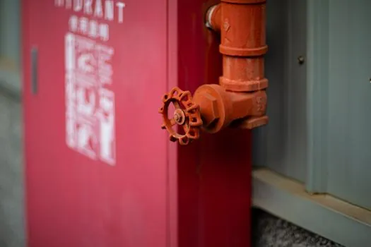
Discharge piping must include a full-bore shutoff valve matched to the line ID, a pressure-relief valve between the pump outlet and the first block valve, a pressure gauge on a straight run between pump and that first valve, and a drain valve between the pump and the first valve for service [S2].
Set the relief valve cracking pressure at or below the pump data-plate maximum, e.g. 150 psi (≈10 bar) class for typical hose pumps, so a dead-headed discharge does not burst the hose; Chem-Tech Series XP data plates list maximum pressure in both psi and bar and maximum ambient at 104 °F (40 °C), and those values are the binding acceptance limits at commissioning [S8]. A short flexible connector at the discharge flange absorbs the peristaltic pulse and isolates the gauge from hose-induced vibration; do not rely on the hose itself to damp the line [S2][S3].
Electrical, Drive, and Control Wiring
Power supply and control are data-plate driven: 220 V AC 50 Hz single-phase for the 6.5 W CEMS condensate unit, 24 V DC stepper drive for KPAS100-type OEM dosing pumps, 12 V DC for G528-type mini lab pumps, and the OEM data plate is the only authoritative source for V, Hz, current, and IP rating [S1][S4][S6].
Wire the drive to a dedicated breaker with a disconnect within sight of the pump, route signal cables (4–20 mA, RS-485 Modbus, or 0–10 V setpoint) in a separate conduit from the power conductors, and ground the motor frame to the plant ground bus, not to the suction or discharge piping [S4][S5]. The Chem-Tech Series XP installation manual requires splash-guard fitting before energising, and the tubing set, injector valve, and strainer must be on hand at start-up because dry running without fluid is permitted but continuous dead-headed operation is not [S5][S8].
Pre-Start Checks, Acceptance Criteria, and When to Stop
Pre-start: confirm rotation direction matches the cast arrow (clockwise left-in/right-out on the 10 R/min CEMS unit), open the suction valve, crack the discharge valve, verify the strainer is clean, and that the pressure gauge reads zero with the pump de-energised [S1][S5].
Acceptance: at rated RPM, the pump must deliver its nameplate GPD or L/h, and the discharge pressure must stabilise below the data-plate bar/psi maximum [S8]. For KPAS100 stepper-driven dosing, the calibration curve should be re-verified at three speeds across the working range because peristaltic output is approximately linear in RPM but the hose reset volume shifts with back-pressure [S4].
Stop and replace, do not repair, if the hose shows blistering, longitudinal scoring, or has logged more than the OEM cycle-hour limit; on XP-series units, the tubing set, injector valve, and strainer are wear parts and are specified in the manual for periodic replacement rather than on-condition servicing [S5][S8].
Material Compatibility and Common Failure Modes
Peristaltic pumps transport solid, liquid, or gas-liquid mixtures with solids up to 40% of tube ID and tolerate abrasive, corrosive, and oxygen-sensitive media because the fluid only ever touches the hose, but they are strictly prohibited from handling media with hard particles or substances that crystallise in the hose [S2].
For acid CEMS service the wetted path is specified in PVDF, including OD 6 mm connectors and OD 7.5 mm / ID 4.3 mm × 120 mm pump pipe, because PVDF resists acid and alkali attack and is stable in moisture-rich streams [S1]. Most premature hose failures trace back to three installation errors: undersized suction piping, missing strainer allowing debris into the hose, and missing pressure relief allowing dead-head overpressure, all of which are flagged in the supplier pipeline guide and which the peristaltic pump operating envelope is not designed to absorb [S2].
Application Match-Up: Where Peristaltic Wins and Where It Loses
Peristaltic pumps are the right call for dirty, shear-sensitive, or sterile-isolated dosing: CEMS condensate drains, fermentation feed, inkjet ink, chemical-metering skids, and food or pharmaceutical transfer where the fluid must never touch a mechanical seal [S1][S4][S7]. They are wrong for clean, high-head, continuous water service where a centrifugal pump or a gear pump is more efficient, and for the high-pressure, high-flow chemical-transfer duty handled by a diaphragm pump they lose on flow-per-kilowatt even though they win on solids handling [S9].
SRS Direct publishes industrial hose-pump frames in 0–10, 0–20, and 0–50 GPM classes with 1/2", 1", 2", 3", and 4" threaded (FNPT), flanged (RF150), or Tri-clamp ends, and the install engineer should size to the 1–3-size-over-inlet suction rule and the data-plate bar limit before selecting the connection standard [S2][S9]. For lab-only dosing, the Hanchen BT100-2J drive with a YZ1515x head is typical, and its enclosure ratings rather than the chemical hose dictate IP choice [S10].
Standards, Documentation, and Sourcing Trail
There is no single ISO or ASME standard that governs a peristaltic pump's piping installation; instead, the binding documents are the OEM installation, operation, and maintenance manual, the data-plate maximums (psi/bar and 40 °C ambient), and the plant piping class, with the supplier pipeline guide supplying the geometry rules [S2][S8].
Verify at hand-over that the IOM, the tubing-set part number, the strainer mesh, the relief-valve cracking pressure, and the data-plate bar/psi are all listed on a single commissioning sheet, because hose-life warranty claims are routinely denied where these references are missing [S5][S8]. For broader pump-spec context in adjacent process skids, see this TIG welding spec map and this submersible pump TCO piece, which both apply when the peristaltic is being plumbed into a larger welded or pumped skid.
Trackable signals over the next quarter: revision cycles of the Series XP and BT100-2J manuals on the OEM document portals, any update to the JIHPUMP pipeline guide that changes the 1–3 size suction rule, and fresh CEMS drain-pump variants that push the 10 R/min / 0.6 L/h baseline above 1 L/h, which would force a re-check of the PVDF connector OD 6 mm line sizing [S1][S5][S10].