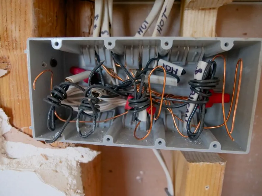
Industrial power distribution box sizing is governed by a single physical constant: one DIN-rail module equals 18 mm, so a 1P miniature circuit breaker consumes 18 mm of rail width and a 2P breaker or residual current device (RCD) consumes 36 mm [S1][S3].
That 18 mm module is the only universal anchor in a market where there is no single mandatory enclosure size standard; final cabinet dimensions are derived from circuit count, breaker type, conductor cross-section, and the IP/IK rating demanded by the installation environment [S3][S6].
The 18 mm Module Logic and Why It Drives Every Width
Every width calculation on a power distribution box starts from the same arithmetic: total internal width in mm ≈ (number of 1P ways × 18) + (number of 2P or RCD ways × 36) + side clearance for DIN-rail end caps and incoming cable bending radius [S1][S3]. The PZ30 residential series uses exactly this 1 unit = 18 mm logic, with 4-6 unit boxes at roughly 200×300×90 mm, 8-10 unit boxes at 250-300×300×90 mm, and 18-20 unit duplex boards at 450-500×500-600×100 mm [S3]. For a 36-circuit concealed residential board, a 600×400×120 mm enclosure is the typical selection, and any board that must also house an RCD or electricity meter should be specified at 150 mm depth or deeper to keep wiring inside the bending radius limits [S1].
The 20% growth rule is the cheapest insurance on a project: for a 16-way requirement (ten 120 V circuits at one slot each plus three 240 V circuits at two slots each), the working calculation is (10 × 1) + (3 × 2) = 16 spaces, and the issued-for-construction number is 16 + 2 spares + 20% growth ≈ 22 ways minimum [S5]. Boxes that fail this rule are the ones ripped out six months later when the tenant adds a POS system, specialty lighting, or an EV charger circuit [S5].
Enclosure Dimensions by Application Class
Residential concealed boxes sit in the 90-120 mm depth band because they are sunk into a wall cavity, and the wall groove must be reserved at ≥120 mm to clear the back of the enclosure [S1][S3]. Surface-mounted metal residential boxes are shallower on the wall but wider per circuit, with 300×200×120 mm covering 8-12 ways, 400×300×120 mm covering 12-18 ways, and 500×400×120 mm covering 20-30 ways for larger apartments [S1]. Industrial surface-mounted metal boxes step up to 300×400×150 mm at the small end and 600×800×200 mm or 800×1000×250 mm for medium power and mixed power distributions [S1].
Floor-standing power distribution cabinets follow a different convention: width is selected from 600 mm, 800 mm, or 1000 mm; depth is selected from 600 mm, 800 mm, or 1000 mm; and the standard overall height is 1800 mm or 2000 mm including the 100-200 mm plinth, which is the form factor used in main distribution rooms, data halls, and large industrial feeds [S1]. The GGD-type fixed switch cabinet common on Chinese industrial sites measures 800 mm wide × 800 mm deep × 2200 mm high, and the family also extends to 400×600 mm, 600×800 mm, and 600×1000 mm footprints for sub-distribution [S3]. Across all industrial enclosures, the cabinet itself is built from cold-rolled steel plate 1.2-2.0 mm thick or a flame-retardant insulating material, and wood is explicitly prohibited as a structural element [S3].
Material, Finish, and IP Rating Selection by Environment
Material choice is driven by corrosion risk, mechanical impact risk, and the cleaning regime of the room. Cold-rolled steel with a multi-stage phosphating pre-treatment and a baked polyester powder coat (typically RAL 7035 light grey) is the default for indoor factories, commercial offices, shopping malls, and dry warehouses, where mechanical strength and rigidity dominate the requirement [S4]. Stainless steel 304 is the next step up for moderately corrosive indoor areas, and 316L is specified where chloride exposure, frequent wash-down, or food/pharma hygiene regimes apply [S4]. Polycarbonate and fiberglass enclosures are reserved for lightweight residential boards, outdoor telecom nodes, and corrosive chemical atmospheres where metal is incompatible [S2].
IP rating is the second environment gate. IP54 is the typical minimum for indoor commercial spaces, IP65 is the working minimum for outdoor enclosures exposed to rain and dust, and IP66 or IP67 is specified where the box sees hose-down, temporary submersion, or heavy splashing, with IP67 typically paired with 316 stainless or fiberglass construction [S2]. For a duty where the enclosure also feeds outdoor LED lighting, see the lamps and light fittings spec map for the matching IP and IK requirements on the load side. For hazardous-area Zone 1 and Zone 2 oil and gas installations, the enclosure decision is dominated by ATEX/IECEx certification rather than by IP alone, and a separate selection exercise is required, detailed in the ATEX spec map for oil and gas distribution boxes.
Side-by-Side Comparison: Material, IP, and Duty Match
Four enclosure classes cover almost every industrial specification a process engineer will see, and they are best compared against corrosion resistance, mechanical impact, weight, and cost: [S4]
Polycarbonate (PC) at IP65, 100-200 A, 200-1000 V, suits residential and light commercial; cost is low, weight is low, corrosion resistance is good, but mechanical impact rating is the lowest of the four [S2]. Fiberglass (GRP) at IP67, up to 400 A, suits outdoor telecom, chemical plants, and coastal sites; cost is medium, weight is medium, corrosion resistance is high, and impact is moderate [S2]. Cold-rolled steel with powder coat at IP54-IP65, the standard indoor industrial box, suits factories, plant rooms, and commercial builds; cost is low to medium, weight is high, corrosion resistance is moderate, and mechanical impact is the highest of the four [S2][S4]. Stainless steel 304/316L at IP66-IP67 suits food, pharma, marine, and chemical wash-down; cost is high, weight is high, corrosion resistance is the highest, and impact is high [S4].
For an oil and gas duty, the material decision is overridden by the certification requirement: an ATEX-certified box typically uses stainless or marine-grade aluminium with Ex e or Ex d terminal enclosures, and the comparison matrix above no longer applies, see the ATEX spec map for oil and gas distribution boxes for the matching rules. For the upstream feeding architecture behind a power distribution room, the sizing exercise begins at the upstream breaker, not at the DIN rail, so the cabinet height and busbar rating need to be reconciled with the main LV switchgear first.
Installation Tolerances and Site Rules That Bite the Layout
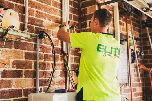
Two installation tolerances decide whether a sized box actually fits. First, the centerline mounting height of a fixed distribution box should be set between 1.4 m and 1.6 m above finished floor level to keep the operating handle inside the comfortable-reach band for the maintainer [S3]. Second, the verticality of the cabinet installation must not exceed 1.5‰ deviation, which is roughly 3 mm over 2 m of cabinet height; exceeding this distorts the door swing, loads the hinges unevenly, and on floor-standing cabinets can twist the busbar chamber [S3]. A clear working clearance of 600-800 mm must be reserved in front of the cabinet, and the door swing must clear any cable tray, fire main, or process pipe in the same zone.
For concealed residential boards, the wall groove depth is the forgotten constraint: a 90-100 mm enclosure requires ≥120 mm of wall groove, and a 100 mm enclosure needs a 130-150 mm groove to clear the incoming cable gland and the RCD wiring space [S3]. A board specified at 100 mm depth that is mounted in a 110 mm groove will fail inspection on cable bending radius even if it physically fits.
Who Should NOT Pick the Default Steel Box
The default 1.2-2.0 mm cold-rolled steel enclosure with RAL 7035 powder coat is wrong for four common duty profiles. First, chloride-rich coastal or de-iced road environments will cut through the powder coat in 2-5 years; 316L stainless or GRP is the correct substitute [S4]. Second, food and beverage wash-down zones require IP66 or IP67 with 316L stainless and a smooth, sloped-top canopy to shed water, not the standard indoor IP54 steel box [S4]. Third, ATEX/IECEx Zone 1 and Zone 2 hazardous areas require certified Ex e or Ex d enclosures from a named manufacturer with the certificate number on the nameplate, and a standard industrial enclosure is not acceptable regardless of IP rating. Fourth, temporary or mobile site power on a construction or concrete-batching project should use an IP65 GRP or polycarbonate box, since steel adds unnecessary weight and is more easily damaged in transit; for that duty profile, see the concrete batching plant spec map and the scaffolding and shoring props spec map for the matching site-power rules.
Shortlist Logic: From Load to a Single Part Number

Walk the calculation in this order. Step 1, list every outgoing circuit and tag each as 120 V or 240 V to fix the 1P/2P breaker assignment. Step 2, apply (1P count × 1) + (2P count × 2) to get the base way count, then add 2 spares and 20% growth to land the issued way count. Step 3, convert ways to internal width using 18 mm per way, and add 40-60 mm of side clearance for cable entry and end caps. Step 4, pick enclosure depth: 90-100 mm for concealed residential, 120-150 mm for surface-mounted residential, 150-200 mm for industrial surface mount, and 200-250 mm for floor-standing power distribution cabinets. Step 5, select material and IP rating from the environment matrix above. Step 6, verify the 1.4-1.6 m centerline mounting height and the 1.5‰ verticality tolerance before issuing the layout drawing. [S1]
The two trackable signals for the next spec cycle are the IEC 61439 low-voltage switchgear and assembly standard updates that govern internal busbar and short-circuit withstand on the larger floor-standing cabinets, and the emerging requirement for DC-rated distribution boxes on solar-plus-storage sites, which breaks the traditional AC-only way-count arithmetic. For an upstream linear-motion or roller-guide decision feeding the same plant, see the linear guide spec map and the crossed roller guide spec map, which share the same load-margin and 20% growth logic as the electrical cabinet on the wall.