Linear motion stages need a brake that holds position when power is removed, releases cleanly under servo command, and survives the duty cycle of the linear motion axis it sits on. A practical 2026 RFQ for a spring-applied, power-released unit on a stage with a 5–50 kg moving mass resolves to roughly 1.5–6 Nm of static holding torque at 24 VDC, with a release time under 30 ms and an IP54 enclosure minimum [S2][S4].
Three Chinese mechanical-industry standards, JB/T 11629-2020 for YZPE-series variable-frequency brake motors [S4], JB/T 6456-2022 for YEJ-series IP55 brake motors up to frame 280 [S5], and JB 7841-1995 for YZZ-series elevator brake motors [S7], all define the same building blocks: an electromagnetic actuator that produces braking torque through friction between a fixed stator face and a rotor face, sized so the rated torque exceeds the load's worst-case holding requirement. Treat these as the reference set when the linear stage uses a Chinese-supplied servo brake motor, and align your RFQ fields with them so the quote does not come back with a generic catalog entry.
Scope and Definitions Buyers Must Lock First
Spring-applied, electromagnetically released brakes are the default fail-safe choice on linear stages because loss of power engages the brake, a behaviour JB/T 11629-2020 codifies as "used to generate braking torque for fast stop or load holding, divided into DC and AC types" [S4]. The Chinese term 电磁制动器 (electromagnetic brake) covers both classes, and the standard breaks it into the brake frame, friction element (制动件), and actuating mechanism, with the friction material split into metallic (cast iron, steel, bronze, powder metallurgy) and non-metallic (leather, rubber, wood, asbestos) families [S8].
For a linear motion stage, the RFQ must define the working envelope: travel length, peak velocity (commonly 0.5–2 m/s for ball-screw stages, higher for linear-motor stages), positioning repeatability (typically ±1–5 µm), and the maximum deceleration the load and screw can absorb without backlash damage [S6]. These four numbers set the minimum dynamic torque, and the static holding torque should be sized to at least 1.5x the worst-case gravitational plus acceleration load, a common engineer rule that prevents drift on vertical or inclined axes.
RFQ Line Items: What to Write, What to Skip
A 2026-ready RFQ line for the brake subassembly on a linear stage should carry, at minimum, these ten fields, each with a value or a deliberate "N/A" so the vendor cannot wedge a low quote in by omission: [S2]
1. Actuation type: spring-applied, power-released (fail-safe). Alternatives are power-applied, spring-released, which fail open and are wrong for vertical axes.
2. Supply voltage: 24 VDC is the default for stage electronics, with 90 VDC or 205 VDC options on larger brake motors per JB/T 11629-2020 [S4].
3. Static holding torque (Nm): size to 1.5x the moving-mass load, with the safety factor stated explicitly so a vendor cannot substitute a smaller catalog unit.
4. Release response time (ms): typically 10–30 ms for spring-applied units; engage time 5–20 ms, both critical for E-stop loop budgeting [S2].
5. Friction-lining class: per JB/T 11629-2020 / JB/T 6456-2022 the lining material must be declared, and metallic versus non-metallic drives different thermal limits [S4][S5][S8].
6. Enclosure rating: IP54 minimum for general industrial stages, IP65 for washdown or cleanroom-adjacent lines; YEJ-series IP55 is the established Chinese reference [S5].
7. Thermal class: insulation class B, F, or H, and the maximum allowable lining temperature rise, which JB/T 6456-2022 caps in its test method section [S5].
8. Hub bore and mounting: keyed or clamp-style, with the brake frame matched to the servo motor frame (e.g. 60, 80, 130 mm) so the motion controller feedback device and brake release lead exit on the same side.
9. Brake control wiring: separate connector, shielded twisted pair, with a release command sourced from the drive's brake output (typically a 24 VDC solid-state relay rated for the inrush current, often 3–5x the holding current for 50–200 ms).
10. Standards compliance: state the standards the build must satisfy. For Chinese-supplied brake motors, JB/T 11629-2020 [S4] or JB/T 6456-2022 [S5]; for elevator-style applications JB 7841-1995 [S7]; for OEM assemblies, the relevant IEC brake test sequence the vendor will run.
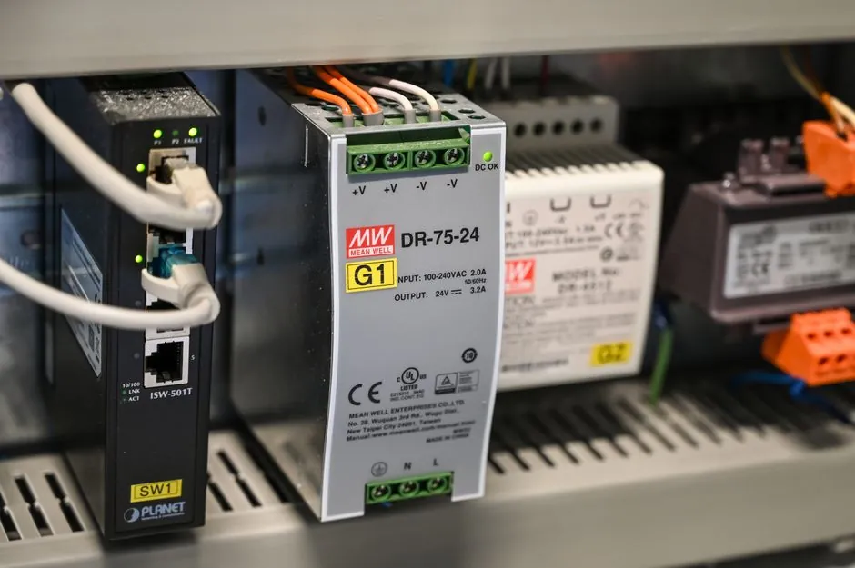
Two fields that reliably cause requote cycles when left blank are the release-command current draw and the maximum ambient. The first determines whether the existing 24 V rail can hold two brakes simultaneously without sagging; the second is the difference between a stock catalogue brake and a high-temperature lining that still holds at 80 °C cabinet interior.
Selection Criteria: Power-On vs Power-Off, Friction Class, and Control
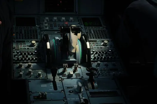
Across the four electromagnetic brake families that appear on stage RFQs in 2026, power release / spring applied, power apply / spring released, permanent magnet, and tooth (face-tooth) technology [S2], the linear-stage decision narrows fast. Permanent-magnet units hold with zero power draw and release under a reverse coil pulse, which suits battery-powered AGV axes but is overkill for a mains-powered stage. Tooth-technology brakes give very high torque density in a small envelope and are common on machine-tool rotary axes, but the backlash profile of a tooth coupling is wrong for a precision ball-screw stage that needs sub-5 µm repeatability [S2][S6].
The criteria-based comparison below lines the main options against the four numbers a stage designer actually cares about:
1. Fail-safe default: spring-applied, power-released, locks on power loss [S4]. Power-applied, spring-released, releases on power loss, and is unsafe on vertical or suspended loads. Permanent-magnet brakes are fail-safe by magnet default, but require a controlled reverse pulse to release, which complicates the motion controller interlock [S2].
2. Typical static torque density: spring-applied units from 1.5–6 Nm at 24 VDC for stage-size brakes; permanent-magnet units overlap that band; tooth units push 10–100 Nm but in a larger frame [S2].
3. Release response: spring-applied 10–30 ms, permanent-magnet 30–80 ms, tooth 5–15 ms, the last being the reason tooth units sit on high-cycle machine-tool spindles rather than on linear stages where the wiring harness, not the brake, dominates the E-stop budget [S2].
4. Maintenance: all four classes have a wear limit on the friction face, defined as a permissible air-gap increase before re-adjustment. JB/T 6456-2022 sets the inspection rule and the air-gap envelope for YEJ-series units, and the same envelope should be written into the stage RFQ so a worn brake is caught during scheduled PM rather than during a positioning drift fault [S5].
For a horizontal ball-screw stage with a 5–50 kg moving mass, a 24 VDC spring-applied unit in the 1.5–6 Nm range, IP54, metallic friction lining, insulation class F, and a hand-release lever option, is the configuration that will quote cleanly across Warner Electric, Keyence SV-D5AG-class brake motors, and the Chinese JB/T 11629-2020 / JB/T 6456-2022 supply base [S2][S3][S4][S5].
Use Cases: Where Each Configuration Earns Its Place
Horizontal pick-and-place stages, conveyor-indexing stages, and lab automation axes share the same default: a 24 VDC spring-applied brake sized to roughly 1.5x the moving mass torque, with the electromagnetic brake engaged as the default state and only released when the servo is enabled. The Keyence SV-D5AG flexing-resistant brake cable, 5 m, is a representative example of the dedicated, oil-resistant, flexing-rated wiring that stage builders specify to connect the brake to the drive, because a generic cable fails first at the strain-relief grommet after a few million cycles of axis travel [S3].
Vertical or inclined stages invert the math: the brake must hold full gravitational load at zero power, and the RFQ must add a "static hold at zero current" test, not just a rated torque number. Warner Electric's power-release / spring-applied family is the explicit catalogue match for this duty, and the standard reference is the same JB/T 11629-2020 clause that requires the brake to maintain holding torque with the coil de-energised [S2][S4].
High-cycle indexing stages (more than 60 cycles per minute) push the friction-lining class upward. Non-metallic linings (rubber, asbestos-class substitutes, resin-bonded) give a higher and more stable coefficient at low temperatures but wear faster; metallic linings (powder-metallurgy, bronze) tolerate higher energy per cycle and are the right pick for an indexing stage or a stage driving an electromagnetic clutch downstream [S8].
Limitations, Failure Modes, and What the Standard Doesn't Catch
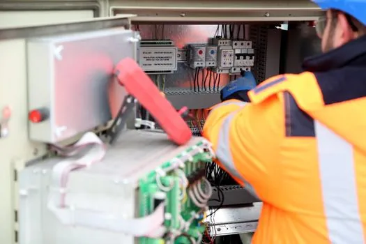
Three failure modes show up repeatedly on linear-stage brakes in the field, and only one of them is fully covered by the standards listed in the RFQ. First, air-gap drift as the lining wears, addressed in JB/T 6456-2022 by the inspection rule and the manual re-adjustment procedure, but only if the maintenance interval is written into the RFQ acceptance criteria [S5]. Second, release-voltage sag, where the 24 V rail droops under simultaneous multi-axis braking and the brake fails to release, a wiring-and-power-design failure rather than a brake failure, and the standard does not test for it. Third, thermal fade in the friction face is governed by operating temperature and the rate of temperature rise, which are the dominant factors affecting the performance of friction materials used in electromagnetic braking [S8].
Warner Electric's product taxonomy also surfaces a class distinction worth quoting on the RFQ: spring-applied units are split into fixed-torque and variable-torque sub-types, and tooth-technology brakes exist in both fixed and variable torque variants as well, so the RFQ must specify which one is required, or the vendor will quote the cheapest [S2]. Variable-torque spring-applied units allow torque adjustment through the air gap or coil current, useful on a stage that handles a range of payloads, but they introduce a calibration step that fixed-torque units do not.
Finally, the standards cited above govern the brake motor as an assembly; they do not cover the integration of a brake into a third-party linear stage. The RFQ should therefore add a clause requiring the vendor to demonstrate engagement and release under the actual servo drive and motion controller combination that will be used, not just under a bench supply, because the inrush profile of a real 24 VDC solid-state brake output differs enough from a bench supply to flip a marginal release-time spec into a fail.
RFQ Checklist and Quote-Acceptance Criteria
To prevent a 2-week requote cycle, the RFQ acceptance criteria should mirror the JB/T 11629-2020 and JB/T 6456-2022 test-method structure as closely as possible [S4][S5]. State, in writing, that the vendor must report: rated static holding torque measured at the actual supply voltage; release and engage time measured with the production wiring harness; air-gap inspection interval in cycles; lining temperature rise after the rated duty cycle; insulation class and dielectric test result; and the IP rating verified by the test lab, not declared on the datasheet.
Two further items separate a clean quote from a requote: ask for the friction material grade by name (e.g. "non-asbestos organic, class B friction coefficient" or "powder-metallurgy, class C"), and ask for the brake-release coil current at 20 °C and at the maximum ambient. A magnetic flow or clutch-brake assembly elsewhere on the line may share the same 24 VDC rail, and the inrush stacking of two or three brake releases is the most common cause of intermittent release faults on multi-axis stages. The electromagnetic brake selection is rarely the failure root cause; the power architecture around it is.
Final node: align the chosen brake with a brake resistor sizing review on any axis that regenerates under hard deceleration, because a regenerative event can pull the 24 V rail above 28 V and either chatter the brake release or pop the brake driver FET. A clean 2026 RFQ for a linear motion stage treats the brake, the motion controller, and the brake resistor as one power-and-safety budget, not three separate line items.
Related analysis: Cold Milling Machine Selection for Urban Road Works.