Modern robotics production cells are built from four functional layers: the manipulator (serial-link arm or gantry), the drive stack (servo motors, gearboxes, controllers), the perception stack (2D/3D vision, force/torque sensing), and the supervisory controller (PLC or industrial PC) — and each layer carries its own spec sheet, vendor shortlist, and integration risk [S1].
On 2026-06-29, the dominant architectures remain six-axis articulated arms for discrete assembly, SCARA for high-speed pick-and-place, and Cartesian gantries for large-format dispensing; payload classes split cleanly at 6 kg, 20 kg, 60 kg, and 220 kg brackets, and repeatability is specified at ±0.02 mm for the precision tier versus ±0.05 mm to ±0.1 mm for general handling. The safety frame is set by ISO 10218-1/-2 (industrial robot safety) and ISO/TS 15066 (collaborative robot limiting values), with power-and-force-limiting (PFL) collaborative cells capped at the contact-energy thresholds the TS documents for quasi-static and transient contact.
Manipulator Kinematics and Reach Envelope
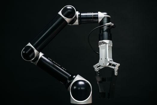
Six-axis articulated arms dominate the 3 kg to 1,500 kg payload band and are the default for automotive body-in-white, arc welding, and machine tending; reach envelopes cluster at 700 mm, 900 mm, 1,400 mm, 1,850 mm, and 2,500 mm working radii, with repeatability published per ISO 9283 (manipulating industrial robots — performance criteria) [S1].
SCARA arms are specified when the cycle is vertical-assembly dominated and floor footprint is tight — typical 400 mm to 800 mm reach, 1 kg to 20 kg payload, and cycle times quoted at 0.3 s to 0.6 s for a 25 mm × 25 mm × 25 mm "pick-and-place" benchmark. For long, narrow work envelopes such as PCB assembly or syringe filling, Cartesian XYZ gantries are the lower-cost pick because linear axes are sourced as standard catalog stages and the PLC controller drives them directly over EtherCAT or PROFINET without a proprietary robot controller in the loop.
Collaborative robots ("cobots") are a kinematic family of their own — 6 kg, 10 kg, 12 kg, 16 kg, 20 kg, and 30 kg payload tiers are common — and the critical spec is not reach but the contact-force / contact-pressure limits in ISO/TS 15066, which are evaluated at quasi-static and transient contact regions of the operator body (e.g. hand, forearm, chest). For mixed human-robot zones the cell must declare either PFL, speed-and-separation monitoring (SSM), hand-guiding, or power-and-force-limited safety-rated monitored stop as the operating mode.
Drive Stack: Servo Motors, Gearboxes and Encoders
Every production-grade arm runs on permanent-magnet AC servo motors at the joints, sized by continuous torque (Nm) and speed (rpm) curves, then derated through a backlash-rated RV reducer or harmonic-drive gear — backlash below 1 arc-min is the typical premium spec, with 5 to 10 arc-min the general-purpose figure [S1].
Selection logic on a 2026 build: start from the worst-case joint torque during the heaviest point on the trajectory, multiply by a 1.5× to 2× service factor, then verify the servo can deliver the RMS torque continuously without thermal trip. The choice between a servo motor and a stepper matters for any axis that closes a position loop under varying load — steppers lose steps when overloaded and are now used mainly on Z-axis lifts, indexing tables, and low-cost Cartesian stages; closed-loop servos with absolute multi-turn encoders (17-bit, 23-bit) are the default for the main path axes. A useful baseline number: a 400 W, 3,000 rpm servo with a 50:1 RV reducer delivers roughly 20 Nm at the joint and positions a 5 kg payload to ±0.02 mm in the published repeatability test.
Wiring and fieldbus shape the panel layout. EtherCAT, PROFINET, and EtherNet/IP are the three industrial Ethernet options; on the safety side, CIP Safety, PROFIsafe, and FSoE (Fail Safe over EtherCAT) carry STO/SS1/SS2/SLS functions over the same cable. Robot vendors publish their own bus map and that map constrains the PLC scan budget — 1 ms to 4 ms cycle time is the typical high-performance band for 6-axis to 12-axis cells.
Perception Stack: 2D and 3D Vision, Force Sensing
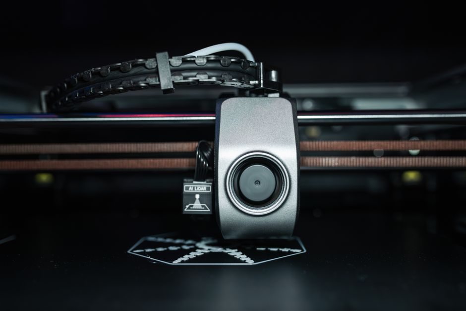
Vision guidance is no longer a "nice to have" — most 2026 cells ship with at least one camera, and a 2D part-location camera on a fixed mount plus a 3D structured-light or laser-line profiler on a robot-mounted head covers roughly 80% of the bin-picking, glue-bead, and seam-tracking use cases [S1].
Spec the perception layer like any other metrology tool. 2D area-scan cameras are quoted by resolution (0.3 MP to 20 MP), pixel pitch (3.45 µm to 9 µm), interface (GigE Vision, USB3 Vision, CoaXPress 2.0), and frame rate (30 fps to 500 fps); the lens is sized for the field of view and working distance, and the illumination (wavelength, structured pattern, polarizer) is the variable that decides whether the system holds up on a glossy black automotive part or a transparent food pack. 3D sensors — laser-line profilers, time-of-flight cameras, and structured-light projectors — publish point-cloud density and Z-resolution, typically 5 µm to 50 µm at the working distance. Calibration routines use a 9-point or 12-point grid to fix the hand-eye transform between robot base and camera frame; a calibrated RMS error below 0.1 mm is the normal acceptance line for a precision pick-and-place cell.
Force/torque sensors at the wrist or joint torque sensing built into the gearbox output close the compliance loop. 6-axis F/T sensors are quoted by measuring range (e.g. Fx/Fy 200 N, Fz 400 N, Tx/Ty/Tz 8 Nm) and resolution, and the published sample rate (1 kHz typical) is what lets the robot do insertion tasks on compliant or slightly misaligned parts. Industry consensus for any contact-rich task (deburring, polishing, assembly of snap-fit plastics) is to keep TCP speed at or below 250 mm/s until force feedback confirms stable contact.
End Effectors and Tool Changing
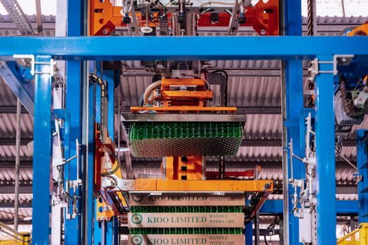
Payload on a spec sheet is the wrist can carry, but the real cell-level throughput is decided by the end effector — gripper, vacuum, or magnetic — and whether the cell swaps it automatically. Pneumatic parallel grippers are still the workhorse for discrete parts, with jaw stroke 5 mm to 30 mm and grip force 50 N to 1,500 N; servo-electric grippers add position feedback and are mandatory where part position has to be verified before release. [S1]
Vacuum grippers are specified by the cup count and diameter — one 40 mm cup lifts roughly 0.5 kg on a smooth surface, derated to 0.2 kg on porous cardboard — and the pump is sized at 60 L/min to 200 L/min depending on the cycle and the leak budget. Automatic tool changers (ATCs) carry 8 to 12 tool positions with locking via pneumatic or ball-detent and signal pass-through rated for 1 Gbit Ethernet, pneumatic (6 bar, 8 bar), and fieldbus; cycle time per tool change is 2 s to 5 s and that figure needs to be in the cycle-time budget, not buried in the cell integration spec.
Cell Control: PLC, Safety, and the SCADA Handoff
The cell controller is a PLC for I/O, interlocks, and sequencing, with the robot controller running its own motion kernel and exposing a recipe interface (OPC UA, MQTT, or vendor-native). Modern robot controllers support OPC UA over TSN as the canonical interface, which lets a plant SCADA swap part numbers and programs without a laptop at the cell [S1].
Safety architecture on a 2026 build is structured around ISO 13849-1 performance level (PL) and IEC 62061 safety integrity level (SIL): a cobot cell routinely lands at PL d / SIL 2, while a fencing-and-interlocked industrial cell targets PL e / SIL 3 on the E-stop and gate-switch chain. Safety functions to budget: STO (safe torque off, category 0 or 1), SS1/SS2 (safe stop 1 / 2), SLS (safely-limited speed), SOS (safe operation stop), and SLP (safely-limited position) — each is a separate function block in the safety PLC, validated on a documented V-model test. The same architecture is reused in Brown University's "Humanity Centered Robotics Initiative" research framing, which treats the human-robot boundary as a hardware + software control problem rather than a procedural rule [S5].
Vendor Map and Selection Cut
On 2026-06-29, the global industrial-robot supplier base is concentrated in Japan (Fanuc, Yaskawa, Kawasaki, Epson), Germany (KUKA, Dürr, Stäubli), Switzerland (ABB), and the United States (Rockwell Automation / Allen-Bradley for the controls layer); China is the largest humanoid-robot design and pilot-production hub, with Datta Robotics in financial distress through 2025 after salary-payment halts and layoffs in the prior 12 months, a signal that the humanoid segment is still capital-constrained [S6].
A spec-driven shortlist looks like this. For 6 kg payloads at 1 m reach with a 1 ms cycle and vision, the shortlist is the Fanuc LR-Mate 200iD, ABB IRB 1200, and KUKA KR 6 R1840 — all three support EtherCAT or PROFINET, ship with a Cat-3 PFL safety option, and are documented at ISO 9283 repeatability. For 12 kg to 20 kg collaborative work, the shortlist is the Universal Robots UR20/UR30, FANUC CRX-20iA/L, and Yaskawa HC30; all three are ISO/TS 15066 rated to the published PFL limits. For 60 kg to 220 kg heavy-payload cells (machine tending, palletizing), the shortlist is the KUKA KR 180 R3200 PA, ABB IRB 6700, and Fanuc R-2000iC — fencing-and-interlocked only, PFL not applicable at that payload. For the controls layer, Siemens SIMATIC S7-1500, Allen-Bradley ControlLogix, and Beckhoff TwinCAT cover roughly 70% of new greenfield cell installs; the right pick is whichever platform the plant standardizes on, not a robot-driven choice.
Common Pitfalls and Acceptance Test Plan

The same failures hit every build that has not been planned against them: cycle time measured at vendor demo is 10% to 30% faster than cycle time at the plant because demo parts are pristine, lighting is controlled, and there is no upstream starvation; payload specified as the rated maximum is paid for in vibration and repeatability, and a 1.5× to 2× derate against the heaviest part is a better operating point than the rated peak. [S2]
Run the acceptance test on three articles and three positions, not one: each part presentation (rotated, offset, flipped) tests the vision calibration and the gripper compliance under real conditions. Force-test the safety chain — STO, SS1, SLS, gate switch — at the published response time, and verify the safety PLC decouples within the maximum response time declared on the PL/SIL calculation. The acceptance test plan is a document: a signed FAT/SAT file with cycle time, repeatability, force, and safety figures, kept in the cell's permanent record. The build is not done until the plant's maintenance team has run the cell on real production for 40 hours with the integration engineer on call, and the open-punch list is at zero before the warranty clock starts.
The robotics research community at Caltech and Brown continues to publish advances in manipulation and human-robot interaction that will feed back into the next product generations on the 24-to-36-month horizon, so the safe engineering assumption on 2026-06-29 is that any cobot cell specified today will need a safety re-evaluation when its next firmware major version lands, not at the end of its depreciation life [S2][S5]. For motion-control sizing that pairs with this build, the servo vs stepper selection cut for 2026 walks through the same derate logic on a single-axis frame, and the EV production technology reference is the closest peer cell where articulated welding and handling are already deployed at automotive cycle times.
For component-level specifications, see pressure transmitter.