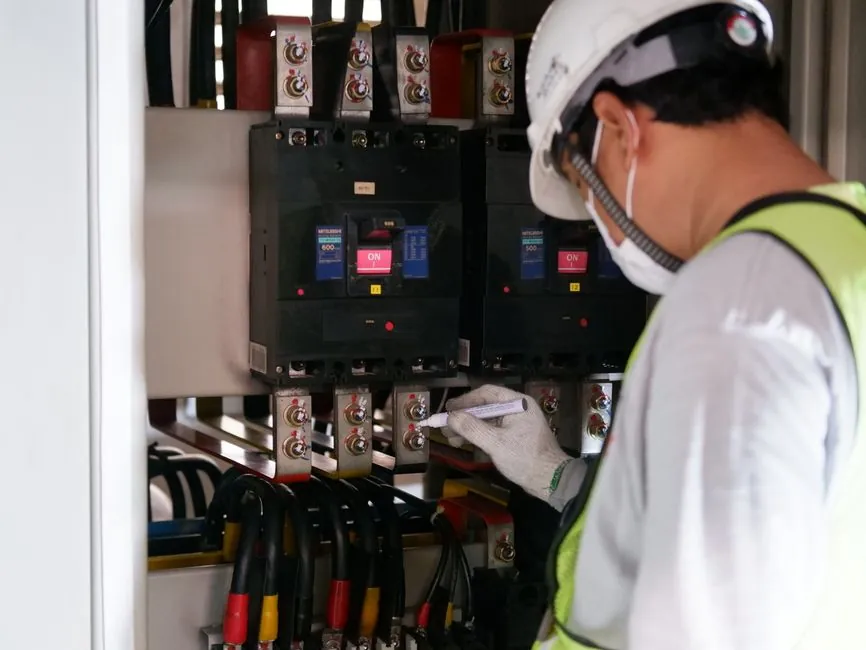
An industrial ultrasonic sensor specified for an OEM control cabinet RFQ is fundamentally a Time-of-Flight device: the unit emits a 40 kHz acoustic pulse, listens for the echo off a target, and converts the round-trip interval into distance, with HC-SR04-class modules quoting 2–400 cm range, 5 V supply, ~15 mA operating current, ~15° beam angle, and ±3 mm accuracy at 40 kHz [S2][S4]. For cabinet builders the engineering task is to translate that hobbyist envelope into an IEC 60947-5-2-conformant industrial device with an M18 or M30 threaded housing, a defined blind zone, and a digital or analog output that lands cleanly on the control cable plan.
Industrial M18/M30 cylindrical ultrasonic sensors in the Telemecanique XX family are explicitly certified to IEC 60947-5-2 with UL and cCSAus product markings, with Sn of 0.50 m, 1 m, or 2 m adjustable and a documented blind zone that no object may enter during operation [S3]. Liquid-level variants such as the Metrolog ULS series extend the range to 0.4–9 m with ±0.2 % FS accuracy, RS-232 / RS-485 / CANopen serial options, and 4–20 mA, 0–20 mA, or 0–10 V analog outputs [S6]. These three families set the realistic RFQ envelope that an OEM cabinet builder should anchor against; HC-SR04 hobby modules sit outside that envelope and should not be quoted in cabinet work.
Line-by-Line RFQ Fields That Prevent Requote Cycles
Five parameters on the RFQ line determine whether an ultrasonic sensor fits a control-cabinet build: nominal sensing distance Sn, blind zone, output interface, housing thread, and certification. Sn on the Telemecanique XX range is adjustable and is offered as 0.50 m, 1 m, or 2 m depending on the M18 or M30 body [S3]; specifying only "ultrasonic sensor" without Sn forces the vendor to default-quote the closest part and the cycle restarts. Blind zone is a contractual exclusion region: the XX datasheet states the blind zone is the volume in front of the face where no object must pass while the sensor is operating, with the consequence that any target entering this zone causes unstable readings [S3].
Output interface is the second-most common omission: a PNP or NPN digital output, a 0–10 V or 4–20 mA analog output, or a serial bus must be declared on the line so the sensor matches the distribution cabinet I/O card. The Metrolog ULS datasheet lists RS-232, RS-485, and CANopen for serial plus 4–20 mA, 0–20 mA, and 0–10 V analog plus 2 PNP open-collector outputs on a single device, which is a useful reference for what a complete industrial ultrasonic part can carry [S6]. Housing thread and length, mechanical mounting, and cable outlet must also be on the line, with M18 x 1 and M30 x 1.5 being the two dominant industrial threads for cylindrical plastic-case ultrasonic sensors [S3].
Industrial vs. HC-SR04: Where Each Architecture Fits
The HC-SR04 module is a 45 mm x 20 mm x 15 mm open PCB with a 4-pin 2.54 mm header, 3.3–5 V supply, <2 mA quiescent current, 15 mA operating current, 112 dB sound pressure, and -65 dB minimum sensitivity [S2]. It is appropriate for Arduino obstacle-avoidance robots, basic parking-assist prototypes, and low-cost proximity alarms [S1][S4]. It is not appropriate for OEM control-cabinet builds because it has no industrial certification, no defined blind-zone guarantee, no threaded housing, and no documented EMC or temperature rating for a cabinet environment.
A direct comparison of the three reference families, on four cabinet-relevant criteria, lines up as follows. Operating range: HC-SR04 2–400 cm theoretical, 2–80 cm practical [S7]; XX 0.50–2 m adjustable [S3]; Metrolog ULS 0.4–9 m [S6]. Output: HC-SR04 TTL trigger/echo only [S2]; XX solid-state digital output [S3]; ULS 4–20 mA / 0–20 mA / 0–10 V plus RS-232 / RS-485 / CANopen [S6]. Certification: HC-SR04 none cited; XX IEC 60947-5-2, UL, cCSAus [S3]; ULS datasheet does not cite IEC 60947-5-2 in the supplied excerpt. Housing: HC-SR04 bare PCB; XX M18 x 1 / M30 x 1.5 cylindrical plastic; ULS industrial sealed body with 5-digit LCD and 4-key menu configuration [S6].
Selection Criteria: Range, Target Surface, and Environment
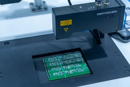
Range must be specified as the maximum operating distance to the target under worst-case conditions, not as the theoretical maximum. The XX family lists nominal sensing distance of 0.50 m, 1 m, or 2 m adjustable on each variant, and the blind zone is a separate, smaller value printed in the datasheet that must be subtracted from any mechanical layout drawing [S3]. For a long-range level application the ULS series extends to 9 m with ±0.2 % FS accuracy and a calibration menu for trimming zero and span, which is the relevant reference when the cabinet I/O is a 4–20 mA analog input scaled to a tank level in litres or cubic metres [S6].
Target surface matters because ultrasonic sensors measure by acoustic reflection: liquid surfaces, flat metal plates, and granular solids each behave differently, and the beam angle of ~15° on HC-SR04 or the equivalent on industrial units defines the cone that must stay clear of obstructions [S2]. The XX datasheet explicitly warns that no object must pass through the blind zone during operation, so a beam tube of that length must be drawn into the cabinet or skid mechanical layout and added to the RFQ as a clearance note [S3].
Environment is the third axis: temperature, dust, IP rating, and EMC class. Industrial M18/M30 cylindrical sensors are designed for factory-floor washdown and dust, while the HC-SR04 is an open PCB that fails in any condensing or dusty environment. Where a sensor is mounted on a cabinet door or on a skid that feeds the MCC cabinet, the IP67 minimum is the realistic floor; vendors should be asked to confirm IP rating on the line alongside the housing thread.
Interface Choices: Digital, Analog, and Bus
Digital discrete outputs (PNP or NPN) are the cheapest and most common interface for cabinet binary I/O, with the XX family offering a solid-state digital output as standard [S3]. For continuous level or distance feedback into a PLC analog input, a 4–20 mA loop is the dominant industrial choice because it shares the same wiring discipline used elsewhere in the cabinet and is intrinsically noise-tolerant over long cable runs; the ULS series offers 4–20 mA, 0–20 mA, and 0–10 V as three ordered variants, which the RFQ should declare explicitly [S6].
Serial buses (RS-485, CANopen, and on some vendors IO-Link) are the third option and matter where multiple sensors are multidropped onto one cable run to the control cable bundle. RS-485 is the most common multipoint industrial bus, CANopen is the dominant choice on mobile equipment and on European machinery, and IO-Link is increasingly specified on new cabinet builds for point-to-point sensor diagnostics. The HC-SR04 has no industrial bus option, only a TTL trigger and TTL echo pin pair, which is another reason it does not belong on an OEM cabinet RFQ [S2][S7].
Two warnings grounded in the research material. First, the practical range of an HC-SR04 is 2–80 cm, while the theoretical range is 2–450 cm, and the gap between those numbers is the usual cause of field failure when the part is misapplied [S7]. Second, the operating frequency of 40 kHz on HC-SR04 is audible to some industrial acoustic alarms and can interfere with other 40 kHz devices mounted on the same cabinet; the RFQ should ask vendors to state operating frequency so co-site interference is caught at quote stage, not at commissioning.
Certification and Standards Anchoring
For OEM control-cabinet builds the standard that anchors ultrasonic sensor specification is IEC 60947-5-2, which covers proximity sensors with defined operating distances, switching frequency, and EMC behaviour; the XX family datasheet explicitly declares conformity to IEC 60947-5-2 and carries UL and cCSAus product certifications on the M30 variants [S3]. Where the cabinet itself is built to a regional scheme (CE in Europe, UL 508A in North America), the sensor certifications should match the cabinet certification to avoid a mixed-certificate build that the inspector must sign off as an exception.
Where the sensor is part of a safety function (SIL-rated guard, level interlock on a hazardous-fluid skid), the RFQ must add a separate line for safety integrity level and proof-test interval; the standard IEC 60947-5-2 alone does not confer SIL capability, and a sensor datasheet that does not state a SIL rating should be treated as non-safety on a safety line. Vendors should be asked to quote safety-certified variants explicitly, with the certificate number and the applicable standard (commonly IEC 61508 for the sensor element) printed on the quote.
RFQ Mistakes That Force a Requote Cycle
Four omissions account for most ultrasonic-sensor requote cycles. First, leaving Sn off the line: the XX family offers 0.50 m, 1 m, and 2 m as three distinct part numbers, and the vendor cannot pick one without knowing the target distance [S3]. Second, leaving blind zone off the line: the blind zone is a hard mechanical exclusion, and a sensor with a 25 cm blind zone cannot be flush-mounted into a 20 cm clearance, no matter what the range is [S3]. Third, leaving output type off the line: a PNP part will not wire into an NPN-only PLC card, and a 0–10 V part will not drop onto a 4–20 mA input without a shunt resistor; both situations force a requote.
Fourth, leaving housing thread and cable outlet off the line: M18 x 1 and M30 x 1.5 use different mounting brackets and different hole punches, and a PVC cable vs a M12 connector vs a fixed pigtail changes the cabinet gland plate layout [S3]. A useful internal checklist for the OEM buyer is: (a) Sn and units, (b) blind zone, (c) output type and range, (d) housing thread and length, (e) cable outlet or connector, (f) IP rating, (g) certification list with IEC 60947-5-2 and any regional marks, (h) operating temperature, (i) operating frequency, and (j) any SIL requirement. Each of those ten items maps to a real failure mode in the research material.
Real Use Cases Inside the OEM Cabinet Scope
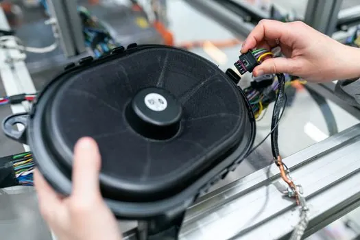
Three use cases dominate ultrasonic-sensor demand inside an OEM control-cabinet scope. Level measurement on a water or chemical skid is the first, with the ULS series covering 0.4–9 m at ±0.2 % FS and a 4–20 mA loop landing directly on a PLC analog input scaled to litres or cubic metres [S6]. Object detection on a conveyor or bin is the second, where M18 or M30 cylindrical digital-output units replace mechanical limit switches and feed the cabinet's 24 V discrete input card via the control cable bundle.
A useful comparative reference for adjacent sensing decisions is the published capacitive sensor compatibility map, which covers the same commissioning-time failure modes for a different sensor technology and is worth reading alongside this article when the target is non-metallic. Adjacent industrial buying decisions such as pump selection for chemical processing and dust detector selection for confined-space entry follow the same RFQ discipline: declare the standard, declare the range, declare the output, and do not leave the vendor to choose.
Trackable signals worth following: confirm whether the cabinet standard (IEC 61439-1 for low-voltage assemblies) is updated and requires a specific sensor-certification line; watch the migration from 4–20 mA to IO-Link on new cabinet builds; and confirm that the chosen M18/M30 part carries a published EMC test report, not just a CE mark, before it is wired into a cabinet that will be CE-marked as a whole. These three items decide whether the ultrasonic sensor adds value or just adds weight to the distribution cabinet.