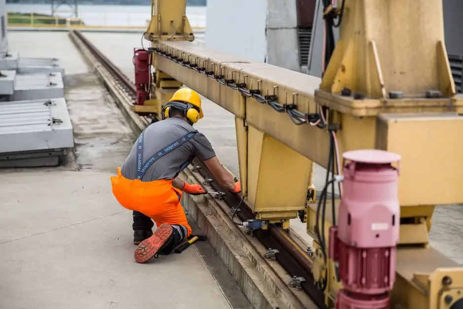
Underhung single girder cranes fitted with mechanical interlock devices can transfer a hoist or carrier from a bridge runway directly into a spur track, eliminating the need to set the load down and re-handle it downstream [S1][S3].
The interlock locks the adjacent ends of two cranes, or a crane and a spur rail, into precise alignment so the trolley can roll across; when combined with a track switch, the same carrier can be routed to multiple branch paths in a ceiling-mounted network [S3][S5]. The published equipment records and vendor catalogs describing this architecture span 2014 through early 2026, with the 2026-02 update from Acculift restating the under-running trolley arrangement that the interlock assumes [S8].
How the Interlock Mechanism Works
An interlock is a mechanical device that rigidly locks the adjacent ends of two cranes (or a crane and a spur rail) so a carrier can traverse from one running surface to the next without re-handing the load [S3]. In patented-track underhung systems the bridge girder is itself a section of running track, which is what makes the transfer geometrically feasible without a separate transfer car [S1].
US patent US3132598A, granted 1965-03-09 to Hill, describes the canonical arrangement: a transfer crane is locked in alignment with the spur tracks via a pin-and-receiver interlock, after which a carrier on the transfer crane rolls laterally into the spur [S9]. TC/American ships this as a standard option on its 200, 325, 400 and 450 Series underhung cranes, with motorised interlocks at both ends of the bridge when both ends feed spurs [S1]. For hazardous-area sites, TC/American offers an Air Motor Driven (AMD) drive variant so that the bridge mechanism stays compatible with classified atmospheres where electric sparking interlocks would be unacceptable [S1].
Underhung vs Top-Running: Why the Interlock Is Cheaper Here
Underhung (under-running) cranes run on the lower flange of the runway beam, so the runway can be suspended directly from the building roof structure without floor-mounted support columns [S3][S5][S8]. Top-running systems sit on rails mounted to the top of the runway and need separate support columns or gantry legs to host a second adjacent runway [S3].
That structural difference is the reason the interlock is practical: an underhung system can install multiple parallel runways side-by-side in a wide bay, and the bridges can pass each other or interlock at the runway ends, while a top-running system would need auxiliary columns or a gantry leg to create the same transfer geometry [S3]. Interlock-based transfer is therefore a low-cost way to stitch separate underhung systems into one fluid material-handling network, rather than buying a single oversized crane to span the whole facility [S3][S5]. For a process engineer specifying a single girder crane into a plant with branch flows, the interlock route typically wins on both headroom and installed cost.
Drive and Brake Options on Interlock-Equipped Bridges
TC/American publishes five drive options that can be specified on an interlock-equipped underhung bridge: Hand Pushed (HP), Hand Chain (HC), Center Motor (MD), Dual Motor (DM), and Air Motor Driven (AMD) [S1]. The MD arrangement uses a centrally mounted motor reducer with drive shafts to each end truck, driving a rubber or poly tire against the underside of the runway flange, which is the preferred choice when critical positioning is required at the interlock landing [S1].
DM is the general-purpose choice, with a motorised steel-wheel trolley on each end truck, while AMD is reserved for hazardous-area operation [S1]. Harrington's underhung single girder line uses helical and spur gearing on the drives and ships adjustable DC brakes plus thermal motor protection as standard, which matters at the interlock because the bridge must stop reproducibly with the trolley aligned to the spur axis [S4]. A safety interlock switch is typically wired in series with the bridge travel limit so the bridge cannot enter the interlock zone until the receiving rail is confirmed locked and aligned.
Track Switches and Spur Routing
A track switch is a moving section of track that diverts a carrier from an incoming fixed track to one of two or more outgoing fixed tracks; interlocks and track switches are complementary, not redundant [S3]. The interlock handles the lateral bridge-to-spur handoff at the runway end, while the switch handles branch selection further down the monorail path [S3][S5].
Hoosier Crane's product literature explicitly markets an "Interlock into a monorail or spur rail with an under running crane system" capability, confirming the standard industry vocabulary for the handoff [S6]. Because the spur track and the bridge girder are both patented-track sections of the same profile, the carrier's wheels do not have to change gauge or profile during the transfer, which is the main reason the interlock can be a passive mechanical latch rather than an active transfer table [S1][S6]. When a crane scale is fitted to the hoist, the weight reading remains valid through the interlock transition provided the carrier does not lift off the rail during the cross-over.
Limitations and Failure Modes
Interlock transfer fails when the receiving rail is not at the same elevation as the bridge girder, when the rails are not collinear within the latch tolerance, or when the safety interlock switch wiring is bypassed so the bridge can drive into an un-locked spur [S1][S3]. Underhung cranes in general are constrained to lighter loads and are most often built as single-girder units for low to medium capacity, so the spur-track architecture is rarely used for the heaviest process lifts [S5].
Mechanical wear on the latch pin, contamination of the spur rail join, and thermal growth that misaligns the runway end are the three most common field failure modes cited in the vendor literature; routine inspection of the interlock landing zone is therefore the maintenance line item that carries the most risk if skipped [S1][S4]. On AMD-driven bridges in hazardous areas, the pneumatic supply itself becomes a single point of failure that an electric bridge does not have, so users should plan redundant air treatment or a fallback drive mode [S1].
Selection Criteria: When the Interlock-Spur Route Fits
The interlock-to-spur architecture fits a facility that already has, or is willing to install, multiple parallel underhung runways, has limited headroom that rules out a top-running crane, and has a process flow that splits into 2-4 branch paths downstream of a main lift station [S3][S5]. It does not fit a heavy-process plant (steelmaking, large casting) where the lift duty points toward a top-running double-girder crane; in that case, transferring a load to a spur would normally be done with a transfer car on rails, not a mechanical interlock [S3].
For a process engineer comparing options, the decision matrix is: load weight and duty cycle (favours top-running above the underhung single-girder range), available headroom and floor clearance (favours underhung), number of branch destinations (favours interlocks plus track switches over a single long bridge), and hazardous-area classification (favours AMD on the interlock bridge) [S1][S3][S5]. A standard published in this space, ASME B30.17, governs overhead and gantry cranes with a top-running bridge, and underhung interlock bridges typically fall under the same inspection and load-test regime by virtue of their bridge-crane classification [S1]. Where the spur joins a gantry crane feed, the interlock geometry has to be checked against the gantry's rail profile separately; this is one of the most common sources of mis-specification in retrofit projects.
The interlock transfer architecture has not changed in principle since the 1965 Hill patent, and the 2014-2026 vendor and integrator catalog pages describe the same mechanism with the same vocabulary [S1][S3][S9]. Two signals to watch over the next planning cycle: any new OSHA or ASME B30 update that revises the inspection interval for interlock latch pins, and any vendor release extending AMD-driven interlock bridges into higher CMAA duty classes than the current light-to-medium range [S1][S4].
Related analysis: Alarm Delay and Signal Averaging: How to Cut Nuisance Trips Without Masking Real Alarms.