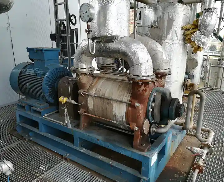
A centrifugal fan, in industrial language a radial fan or process fan, moves air or gas by throwing it outward from an impeller spinning inside a scroll housing: gas enters axially at the eye of the wheel, gains velocity through the blade passages, and leaves tangentially at higher pressure than it arrived, with the scroll converting part of that velocity into static pressure. The impeller family, backward curved, airfoil, backward inclined, radial, open radial, and forward curved, sets the pressure capability, the efficiency, and the tolerance to dust and temperature, and the machine around the wheel, bearings, shaft, housing, drive, and arrangement per AMCA rating practice, sets how the fan survives its duty. Duties run from a few hundred to over a million cubic meters per hour, at static pressures from a few hundred pascals on ventilation to 15 kilopascals and more on forced draft and gas recirculation service.
Procurement engineers meet these fans on boilers and fired heaters as induced draft, forced draft, and primary air fans, on air pollution control trains pushing or pulling through scrubbers, bag filters, and oxidizers, on process exhaust and material conveying, on cooling and dryer service, and on the general ventilation of plants. The decision this page settles is which wheel and which arrangement fit the gas, the dust, and the temperature: a backward curved wheel for clean high efficiency duty, an airfoil for the best efficiency where dust is absent, a radial or open radial wheel for heavy dust and conveying, and the AMCA arrangement, drive, and class decisions that make the machine maintainable. The answer lands as an RFQ line set, flow and density and static pressure, wheel type, arrangement, materials, and options, and every chapter below feeds that line set so the fan is bought against its system curve rather than against a catalog peak.
This page treats the industrial centrifugal fan as a purchasing object: how wheel geometry sets efficiency and dust tolerance, what AMCA arrangements and classes actually specify, how fan laws and system resistance price the operating point, which duties demand spark resistant and high temperature construction, and how the whole decision folds into a defensible RFQ. It is written for engineers who issue fan purchase specifications, not for readers who want a brochure summary.
Chapter 1 / 06
What a Centrifugal Fan Is and What Is Being Decided
The defining act of the machine is dynamic pressure generation by a rotating impeller, and the centrifugal architecture is chosen over axial flow when pressure per stage, resistance to flow disturbance, and noise character matter more than compactness. The scroll housing that wraps the wheel is not decoration: its volute shape decelerates the gas leaving the wheel tip and converts velocity pressure into static pressure, and the cutoff, the tongue where the scroll begins, is close tolerance hardware whose condition directly affects performance and noise. Unlike a roots blower or a screw machine, the centrifugal fan is a continuous flow machine with no positive displacement, so its output rises and falls along a curve against the resistance the connected system presents, which is why a fan is always bought as a pairing of machine and system curve, never as a machine alone.
What is being decided in this purchase is four commitments at once. First a wheel type, because blade geometry fixes the efficiency band, the pressure characteristic, and the dust and temperature tolerance, and it is the single choice most often gotten wrong by copying a neighboring installation instead of reading the duty. Second an arrangement and drive per AMCA practice, since bearing position, fan rotation and discharge designation, and direct or belt drive set the maintenance story and the vibration behavior. Third a rating basis: flow at a stated density, static or total pressure, power, sound, and the AMCA certification class the motor and structure must be sized for, with an allowance for the dirty system resistance growth described in chapter 2. Fourth the duty options: spark resistant and high temperature construction, abrasive wear protection, corrosion materials, and inlet box and damper scope. A buyer who lets the vendor fill any of those in later has bought a wheel and a hope.
Against its neighbors the centrifugal fan occupies precise ground in the air moving spectrum. A regenerative blower, the side channel machine, delivers small flows at moderate pressures with simple hardware and accepts its lower efficiency. A roots blower, the positive displacement lobe machine, delivers low flows at high pressures with a fixed displacement character the centrifugal fan does not have. A turbo blower stands at the high flow end with integral high speed impellers serving aeration duties. A centrifugal compressor, the multi stage machine on a process string, belongs to the pressure and machinery class above all of these. General ventilation duty, covered by the ventilation equipment umbrella page, is the low pressure corner of the same physics, and this page is the industrial authority for it. Stating which neighbor the project is not buying belongs in the RFQ, because every fan vendor sells several of these machines and quotes what was asked.
Standards organize the datasheet, and AMCA practice leads: the AMCA Certified Ratings Program verifies that published performance for certified fan types, centrifugal fans among them, was tested to the association standards, and the AMCA arrangement and class nomenclature, arrangements 1 through 10 for bearing and drive placement, classes I through IV for the pressure and speed capability of the housing and wheel, and spark resistant construction types A, B, and C, gives buyer and seller a common specification language. Sound rating follows AMCA test practice, and vibration limits follow the applicable ISO balance and vibration standards for the class. On boiler and fired heater duties, the induced draft and forced draft fan scope inherits the combustion equipment context of the host plant. A datasheet that quotes flow and pressure with no AMCA basis and no class is a price tag, not a specification.
The station around the fan deserves naming in the RFQ too. Ducting and dampers set the system resistance the fan must overcome, inlet boxes and outlet diffusers recover pressure, and a vfd with an ac motor is the modern turndown handle that replaced damper throttling on most industrial fans. Downstream of draft fans on combustion service sit the burners and the air preheater economy described on their own pages; on pollution control trains the fan is sized against the combined resistance of a bag filter or scrubber and its fouling allowance. Instrumentation reads the machine: a pressure transmitter or gauge each side of the fan for the developed pressure, a vibration sensor on each bearing for condition monitoring, and motor current as the cheap power indication. A soft starter or vfd tames the starting current of the larger wheels. Buying the fan without its system is how startup arguments begin.
Chapter 2 / 06
How the Wheel and the System Curve Set the Operating Point
The fan curve and the system curve intersect, and that intersection is the only flow the plant will ever get. The fan curve, pressure against volume at a fixed speed and density, falls from shutoff toward free delivery; the system curve rises with the square of flow, because ducts, filters, banks of heat exchanger surfaces, and stacks all resist roughly with velocity squared. Add fouling, a bag filter loading with dust or a scrubber packing scaling, and the system curve steepens and the operating point walks up the fan curve to lower flow and higher pressure, which is why the RFQ should state both a clean and a dirty resistance and the fan should be selected between them with the motor sized for the higher power point. The most common industrial fan error is buying the clean point only, then living with an undersupplied system and a motor at its service factor.
The fan laws price every change. Flow varies directly with speed, pressure with the square of speed, and power with the cube, which is the arithmetic behind vfd economics: an 80 percent speed reduction from design costs roughly half the power, and a damper achieving the same flow reduction wastes the difference as throttling loss. The laws also carry density, and density is the industrial trap: gas at 250 deg C weighs roughly half of ambient air, so a fan moving hot flue gas delivers half the mass at the same volume and develops half the pressure. Ratings are therefore stated at a density, and the buyer must translate every quoted number to the actual gas condition, temperature, altitude, moisture, and molecular weight, before comparing vendors. A quotation in volume only, without the density basis, is not comparable to anything.
Wheel geometry sets the shape of the pressure curve and the efficiency at the operating point. Backward curved and airfoil blades slope away from the direction of rotation, give non overloading power characteristics, the power curve flattens instead of climbing runaway toward free flow, and reach peak efficiencies of 80 to 90 percent in good industrial designs. Forward curved blades, the multivane squirrel cage geometry, move large volumes at low pressure with small wheels and quiet operation, at lower efficiency and an overloading power character. Radial blades, plates straight from the hub, tolerate dusty and fibrous gas that would pack a backward curved passage, run at lower efficiency, and self clean by centrifugal action; open radial wheels and various paddle shapes extend that tolerance to heavy solids conveying. The selection is a trade of efficiency against the gas the machine must survive, and chapter 3 maps it.
The operating point should sit where the fan wants it. Peak efficiency lives in a band, typically 60 to 85 percent of free delivery flow depending on wheel type, and a selection at the far left of the curve, high pressure at low flow, pays for its point with instability: the stall region, where flow separates on the blades, surges and pulses, and the fan harmonics ring through the ductwork. Turndown must therefore be argued as a curve question, not just a speed question: a vfd moves the whole curve down and left along the system curve and keeps the operating point in stable country, while damper throttling pushes the point left along a fixed curve toward the stall region. On applications needing wide turndown, inlet vane control, which pre swirls the flow and reshapes the curve, sits between those extremes, and the selection chapter prices the options.
Sound and vibration complete the physics the buyer pays for. Fan sound rises with tip speed and duty, and the specification should demand octave band sound power data per AMCA practice, not a single decibel number, because the plant silencer and the neighbor complaint are frequency specific. Balance quality of the wheel and the drive train sets the vibration baseline, and the resonance survey, wheel and structure natural frequencies against operating speed ranges, belongs in the vendor scope on larger machines, because a resonance found at startup is a structural project, not a tuning issue. Spark resistant construction types and its AMCA definitions, and high temperature construction with cooled or standoff bearings, are the option packages that answer hazard and heat, and they change the bearing and clearance design, not just the nameplate.
Chapter 3 / 06
Wheel Types, Arrangements, and Duty Boundaries
The industrial catalog reads in wheel families. Backward inclined flat blades give a robust non overloading curve at good efficiency for clean and lightly dusty gas, the default process fan. Backward curved, with the blade edge curved against rotation, improves the efficiency further and holds the curve shape tightly. Airfoil blades, hollow or formed wing sections, reach the best efficiencies, commonly into the mid 80s percent and above on large machines, and demand clean dry gas because dust erodes and unbalances an airfoil section faster than a flat plate. Radial blades and radial tipped designs trade 10 to 20 efficiency points for dust tolerance, running in baghouse and precipitator service, mill exhaust, and material conveying where a backward curved passage would pack solid. Forward curved multivane wheels serve low pressure ventilation, heating coils, and light industrial duty where quiet compact airflow is the product.
AMCA arrangement numbers fix the mechanical layout and should be named in the RFQ. Arrangement 1, wheel overhung on a bearing pedestal with belt drive, is the economical general purpose layout, easy to maintain and common on small and medium fans. Arrangement 3, bearings on both sides of the wheel with belt drive, and arrangement 8, the direct coupled overhung layout with the motor on an extension shaft, serve medium duties with better balance. Arrangements 4 and 7 put the wheel on a through shaft supported by fan bearings with the drive outside, arrangement 7 direct coupled, which is the heavy industrial standard for induced draft and forced draft service where maintenance access and bearing life carry the warranty. Arrangement 10, belt drive with the motor inside the fan base, packages smaller units. Each arrangement has a maintenance and vibration character, and the buyer who names it keeps vendors comparable.
Duty classes and construction options write the rest of the specification. AMCA class, I through IV, states the pressure and speed capability envelope of the housing and wheel construction, and undersizing the class to save capital shows up as housing flex and wheel stress on high temperature or high resistance duty. Spark resistant types A, B, and C move the construction toward nonferrous or non sparking contact combinations for explosive laden gas, and the buyer should remember the AMCA definition is a construction practice, not a guarantee against ignition of every mixture, so the process hazard analysis still owns the decision. High temperature construction, with features from standoff bearings and cooled shaft pass to expanded clearances and higher class materials, serves induced draft fans on boiler service where the gas may arrive at 200 to 450 deg C. Wear protection, hardfacing, replaceable liners, and chromium carbide coatings, extends radial wheels in abrasive service. Corrosion materials, 304 and 316 stainless, and specialty alloys, answer acid and chloride laden gas off scrubbers and dryers.
Boundaries are worth stating bluntly. A centrifugal fan is not a positive displacement machine: duties needing 30 kilopascals and above at small flow belong to a roots blower, and duties needing 100 kilopascals and above belong to the compressor pages, the centrifugal compressor at high flow and others at low. It is not the general HVAC ceiling fan or cabinet fan of building services, which the ventilation equipment page covers at low pressure, and it is not a regenerative blower, whose side channel principle serves a small flow niche with charming simplicity. On combustion service the fan is part of a system with burners, ducts, dampers, and controls, and a fan quoted without its system resistance basis is a component quote pretending to be a machine. The type map below compresses the boundaries into one table.
Wheel type
Peak efficiency band
Best duty
Avoid when
Airfoil
Mid 80s percent and above
Clean air, large continuous duty, energy cost dominant
Any dust loading that erodes or unbalances the blade section
Backward curved
High 70s to mid 80s
Clean to lightly dusty process and draft duty
Heavy dust that packs blade passages
Backward inclined flat
70s percent
General industrial process exhaust
Peak efficiency is the purchase driver
Radial and radial tipped
60s percent
Dusty gas, baghouse and precipitator service, conveying
Clean gas where the efficiency loss buys nothing
Open radial paddle
Under 60 percent
Heavy solids and fiber conveying, severe service
Anything cleaner that a radial blade survives
Forward curved multivane
60s percent, low speed
Low pressure ventilation and light industrial air
Industrial dust or pressure above a few kilopascals
Chapter 4 / 06
Key Specification Parameters
The table below decodes the datasheet lines that decide whether a quoted fan matches the system and the gas. Each row is a purchase defining parameter; the paragraphs after the table explain what to demand and what a weak answer looks like.
Attribute
Typical range or options
What it decides
Volume flow
500 to 1,000,000 m3/h by size
Wheel diameter and speed class for the duty point
Static or total pressure
0.3 to 15 kPa typical industrial band
Wheel type, stages, and the AMCA class required
Gas density basis
Temperature, altitude, moisture, molecular weight
Translation of every rating number to real conditions
Gas condition
Clean, dusty with loading, temperature, corrosive
Wheel family, wear options, materials, and construction type
Wheel type
Airfoil, backward curved, radial, forward curved
Efficiency, dust tolerance, and power character
AMCA arrangement and class
Arrangements 1, 3, 4, 7, 8, 10; classes I to IV
Bearing layout, maintainability, and structural capability
Drive and speed control
Direct, belt, vfd or damper or inlet vane
Turndown method, power at turndown, starting behavior
Power and motor
kW at design and at dirty system point
Motor frame, service factor use, and starting current scope
Sound
Octave band sound power per AMCA
Silencer scope and neighbor and operator exposure
Options
Spark resistant A B C, high temperature, wear, materials
Hazard, heat, and corrosion survival of the whole machine
The density and system rows carry the warranty. Every rating must arrive with its density basis, and the buyer must restate flow and pressure at the actual gas temperature and composition before comparing quotations, because a fan selected on ambient air numbers and then asked for 300 deg C gas will deliver half the pressure the system needs. The dirty resistance row matters just as much: state clean and expected dirty system pressure drop, select the fan between them, and size the motor at the higher power point with the fan law check, because power climbs as the operating point walks. A quotation that states one flow and one pressure with no density and no system context is not a fan selection, it is a coordinate.
The arrangement and control rows set the maintenance and energy story. Name the AMCA arrangement so bearing layout and drive access are comparable, and name the turndown method with its energy arithmetic: vfd speed control follows the cube law and keeps the point stable, damper throttling wastes power and walks toward stall, and inlet vanes sit between. On combustion duties the response speed of the draft control belongs in the control scope, not just the fan. The second table compresses the duty options the way a specification meeting argues them.
Duty condition
Construction to specify
Check before order
Boiler induced draft, 200 to 400 deg C gas
Arrangement 7, high temperature construction, radial tipped or backward curved
Bearing cooling, expansion, and dirty resistance allowance
Forced draft combustion air, clean
Airfoil or backward curved, vfd control
Motor sizing at damper failure and design points
Baghouse or precipitator exhaust, dusty
Radial tipped wheel, wear options, arrangement 3 or 7
Bridging of dust loading on wheel balance; access
Corrosive gas off scrubber or dryer
316L or alloy wheel and housing, sealed bearings
Dew point margin and wash provisions
Explosive laden gas
AMCA spark resistant type by hazard analysis
Process still owns ignition decision; instrumentation scope
Material conveying, heavy solids
Open radial paddle, replaceable liners
Erosion life basis and liner change interval
Chapter 5 / 06
Selection Decision Factors and RFQ Language
The decision sequence is short enough to run as a specification meeting checklist, and each step eliminates a class of quotations before price comparisons begin.
State the gas honestly: composition, temperature, moisture, dust loading and particle character, corrosive content, and explosive potential, because wheel family and construction follow from the gas, not from the flow number.
Compute the system resistance at design and dirty conditions, including every element the fan must overcome, filters, banks, dampers, and stack, and state the two points in the RFQ.
Restate flow and pressure at actual density, then select wheel type against the gas and the efficiency target, using the chapter 3 map.
Name the AMCA arrangement and class, the rotation and discharge designation, and the drive scope, direct or belt, with the vfd or damper turndown method and its energy arithmetic.
Size the motor at the worst credible point with the fan laws, not at the brochure point, and state starting method, soft starter or vfd, for the larger wheels.
Specify the options the duty demands: spark resistant type, high temperature construction, wear protection, corrosion materials, inlet box and damper scope.
Demand the data: certified performance per AMCA at the stated density, octave band sound, balance quality, and the resonance and vibration basis for larger machines.
Fix the verification evidence: witnessed performance test where the duty justifies, vibration and sound acceptance numbers, and the warranty basis at the actual gas condition.
Against neighboring equipment the comparison a specifier needs runs as follows, and it belongs here in the selection chapter rather than in the page title. A regenerative blower serves small flows at moderate pressure with simple hardware and forgiving behavior. A roots blower delivers low flows at high pressure with positive displacement certainty. A turbo blower owns the high flow aeration niche with integrated high speed drives. A centrifugal compressor belongs to the process machinery class above, multi stage on a string with seals and vibration monitoring. The ventilation equipment page covers the low pressure building corner. The centrifugal fan takes the industrial middle: high flows, pressures to roughly 15 kilopascals per stage, dust and temperature tolerance built by wheel and construction choice, and efficiency that pays for good selection every operating hour. Name the neighbors in the RFQ and every vendor quotes the same machine against the same duty.
The RFQ block should be written once and reused. A complete block reads: gas composition with temperature, moisture, density basis, dust loading and particle description, and corrosive or explosive content; volume flow at the stated density, with minimum and maximum; static or total pressure at clean and dirty system resistance; wheel type named with the reason; AMCA arrangement and class with rotation and discharge; materials of wheel, housing, and shaft; drive scope with motor power at the worst point, vfd or starter, and control interface; construction options, spark resistant type, high temperature features, wear and corrosion provisions; inlet and outlet scope, boxes, dampers, silencers, and flexible connections; sound data per octave band; vibration and balance basis with the resonance survey scope on large machines; instrumentation, pressure reading each side, vibration sensor per bearing, motor current; and the test and certification deliverables. A quotation returned without the density basis or the dirty point is incomplete at any price.
Chapter 6 / 06
Installation, Standards, Failure Modes, and Maintenance
Installation quality decides whether the rated performance appears in the duct. Inlet conditions dominate: a fan curve is rated with uniform flow into the eye, and an elbow or a damper bolted hard against the inlet can cost several percent of performance and start vibration problems, so the RFQ and the layout should respect the straight duct the vendor rated, or the vendor should rate the real inlet with boxes and screens. Foundations carry the dynamic load, flexible connections isolate the duct growth from the casing without fighting it, and alignment of direct drives follows the same discipline as any rotating machine. Belt drives go on with correct tension and sheave alignment, because belt vibration masquerades as wheel imbalance and eats bearings until someone checks it.
Commissioning proves the point and the machine. Read developed pressure across the fan with the pressure transmitter or gauges at design damper or speed settings and compare to the curve at actual density, and record motor power against the selection point, because the two together catch most selection and installation errors in an afternoon. Run the vibration survey across the speed range on vfd service and confirm no structural resonance inside the operating band, then set the vibration alarm baselines from the measured values rather than from the manual. Prove the protections: high vibration trip where fitted, motor overload, and the draft or pressure control loop response on combustion duty. On high temperature service, plan the heat run and watch bearing temperatures against the vendor curve before the first full load day.
Failure modes in service follow a short and predictable list. Bearing failure leads the statistics: double suction overhung and arrangement 1 pedestals die of belt tension and imbalance together, arrangement 7 through shaft machines of coupling misalignment and lubrication neglect, and all of them of dust that gets past seals on dirty duty, which is why bearing isolators on baghouse and conveying fans are cheap life. Wheel imbalance grows with dust build and erosion, announces itself in rising vibration at running frequency, and is cured by cleaning or balancing weights, with the balance record kept against the next campaign. Erosion on radial and conveying wheels thins blades at the tips, answered by hardfacing and replaceable liners bought at specification. Structural and acoustic resonance appears after speed or duct changes and is a survey problem, not a damping anecdote. High temperature machines suffer clearance loss and bearing heat when the standoff and cooling features are compromised, and spark resistant constructions demand the maintenance discipline their rivets and clearances were designed for, because a repair that restores an iron rubbing contact cancels the construction type silently.
Maintenance intervals scale with duty severity and gas cleanliness more than with hours. Clean continuous draft fans run bearing lubrication and vibration routes on the plant calendar, with coupling and alignment checks at outages, and their vibration trend is the condition monitoring that schedules anything else. Dusty service moves to periodic wheel cleaning with the balance checked after every clean, wear surveys on lined wheels, and bearing isolator inspection. High temperature and corrosive duties add thermal growth checks and material condition surveys to the outage list. The vfd and motor follow the electrical calendar, and the instrumentation, the pressure and vibration readings that feed the trend, belongs on the same route. Every campaign produces numbers, clean versus dirty resistance, vibration spectra, and wear rates, and those numbers are the calibration for the next RFQ, which is how a purchasing file gets smarter instead of just older.
FAQ
Which impeller type should I specify for dusty gas?
Radial or radial tipped blades, accepting an efficiency penalty of 10 to 20 points against backward curved designs, because straight radial passages shed dust instead of packing it and tolerate the imbalance and erosion that dust brings. If the gas is clean, spend the efficiency on backward curved or airfoil wheels, but never specify an airfoil on dust: erosion and buildup unbalance the blade section quickly and the fan becomes a maintenance project.
Why does my fan deliver less flow than the datasheet says?
Three usual causes. First, density: a fan rated on ambient air and applied on 250 deg C gas develops about half the pressure, so translate every number to actual conditions. Second, system resistance: the real duct, with its elbows, fouled filters, and unmodeled elements, is almost always higher than the design point, and the operating point walks down the curve. Third, inlet conditions: an elbow hard on the inlet disturbs the wheel entry and costs several percent of performance. Measure developed pressure across the fan and compare to the curve before blaming the machine.
What do AMCA arrangement numbers mean in practice?
They fix bearing and drive layout: arrangement 1 overhung wheel on a pedestal with belt drive is the economical general purpose layout, arrangements 3 and 8 suit medium duty with better balance, and arrangement 7, wheel on a through shaft with fan bearings and drive outside, is the heavy industrial standard for induced and forced draft service where access and bearing life carry the warranty. Naming the arrangement in the RFQ keeps vendors mechanically comparable instead of each quoting the layout they prefer.
Should I use a vfd or dampers for turndown?
A vfd almost always wins the energy arithmetic on continuously throttled industrial fans: power follows the cube of speed, so 80 percent speed costs roughly half the power, while damper throttling achieves the flow by adding resistance and wasting the difference. Dampers remain the cheap answer for two position duty, and inlet vanes sit between the extremes on wide turndown at moderate cost. Decide with the load profile and electricity price in the RFQ, not by vendor default.
How do I handle 300 deg C induced draft gas?
Specify high temperature construction with the features that survive it: standoff or water cooled bearings or heat slinger shaft arrangements, expanded housing and wheel clearances, material classes for the temperature, and an AMCA class rated for the speed. Rate the fan at the actual hot density, size the motor for the resulting power, and verify bearing temperature behavior in a heat run at commissioning, because a standard construction fan on hot gas dies in its bearings first.
What does spark resistant construction actually guarantee?
AMCA types A, B, and C define construction practices, nonferrous or non sparking contact combinations and clearance rules, that reduce the risk of sparks from rubbing and contact inside the fan. They do not guarantee that no ignition is possible for every gas mixture, so the process hazard analysis still owns the decision, including grounding, gas detection, and inlet or outlet flame arrester scope where the mixture warrants. Treat the construction type as one layer, not the whole safety case.
How do I verify a fan performance quotation?
Demand certified ratings per AMCA at the stated density, with the operating point marked on the actual fan curve, power at the dirty system point, and octave band sound data. On significant duty, a witnessed performance test to the AMCA procedure settles it. Then translate every number to your actual gas density and system resistance, because a certified curve at the wrong density is certified evidence for the wrong fan.