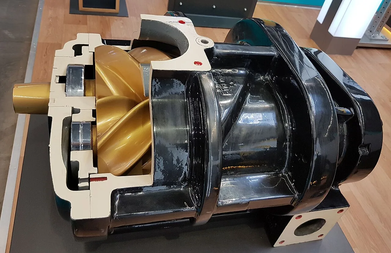
A centrifugal compressor is a dynamic machine, often called a turbo compressor or radial compressor, that raises gas pressure by accelerating flow through rotating impeller rows and then converting that velocity back to static pressure in diffusers and volutes. Where a positive displacement machine traps a fixed volume per revolution, the centrifugal stage makes head, and the discharge pressure it actually develops depends on the system resistance it pushes against. Pressure ratio per stage runs 1.2 to 3, with 1.5 to 2.2 typical in air service, so plant air at 8 to 10 bar is built from 3 or 4 intercooled stages, and flows span from small 30 m3/h chemical machines to process trains above 300,000 m3/h. The oil-free air class delivers ISO 8573-1 Class 0 air, which is why food, pharmaceutical, and electronics plants buy it despite the higher first cost.
Procurement engineers meet these machines as packaged oil-free air stations in plant utility houses, as air separation compressors, and as API 617 process frames on gas gathering, reinjection, CO2, and syngas duty. The decision this page settles is the one that drives every line of the purchase order: which frame class the duty earns, integrally geared or between-bearings barrel, how many stages and how much intercooling, what driver and speed control pair with it, and how much of the antisurge system the supplier owns. The answer lands as an RFQ line set: gas and its molecular weight, flow at stated reference conditions, discharge pressure, stage count, cooling, driver, guarantee basis, and the protection scope.
This page treats the centrifugal compressor as a purchasing object: the stage physics behind the pressure ratio, the frame families and where each earns its cost, the surge map and the antisurge loop that keep the machine alive, the specific power and air purity guarantees worth demanding, and how all of it is written into an RFQ. It is written for engineers who issue purchase specifications, not for readers who want a brochure summary.
Chapter 1 / 06
What a Centrifugal Compressor Is and What Is Being Decided
The defining distinction is dynamic against positive displacement, and it decides everything downstream of the purchase. A screw compressor, the positive displacement reference, traps a measured pocket of gas per rotor revolution and moves it from suction to discharge, so its flow is nearly independent of discharge pressure and its pressure capability is set by rotor strength and drive power. A centrifugal compressor, by contrast, throws gas outward continuously with impeller blades, and the diffuser decelerates that high velocity flow so the kinetic energy becomes static pressure. The radial compressor therefore delivers a head curve rather than a fixed flow: at a given speed it raises pressure by a certain multiple, and the actual operating point is where its curve crosses the system resistance curve. This is why one machine can be throttled, surged, and staged, and why its control philosophy is a purchase decision, not an accessory.
What is being decided in this purchase is five commitments at once. First, the frame class commitment: a packaged integrally geared oil-free air machine in the API 672 idiom for plant air, or an API 617 process frame, overhung, between-bearings beam, or radially split barrel, for hydrocarbon and chemical gas duty. Second, the aerodynamic commitment: stage count and per stage ratio, intercooler count and type, air cooled or water cooled, which set efficiency and the specific power guarantee. Third, the driver commitment: induction motor through a gearbox, motor on variable speed through a VFD, or steam and gas turbines on large trains, each changing the turndown and the map. Fourth, the protection commitment: the antisurge loop, its measurement, its recycle valve, and the API 670 machinery monitoring that trips the unit when the loop fails. Fifth, the mechanical commitment: bearing type, tilting pad or magnetic on premium frames, and seal type, labyrinth and carbon ring air seals or dry gas seals on process machines. A quotation that answers only the flow and pressure lines is a box price, not a machine.
Against its neighbors, the machine occupies deliberate ground, and the full comparison belongs in the selection chapter. The quick map is this: a screw compressor wins below roughly 200 m3/h and wherever deep turndown in a single stage is needed; a roots blower wins low pressure air at modest ratios; a regenerative blower wins small clean low pressure duties where simplicity matters. Below atmospheric pressure the vacuum pump family takes over, and the same buyer who specifies compressors usually owns those too. The centrifugal compressor takes the high flow territory above those classes, from a few hundred cubic meters per hour of plant air to process trains, because the dynamic stage scales in a way positive displacement hardware cannot match.
Four standards organize the datasheet. API 617 governs centrifugal and axial compressors for petroleum, chemical, and gas industry service, fixing rotor dynamics, testing, and documentation expectations on process frames. API 672 governs packaged, integrally geared, oil-free centrifugal air compressor packages for general refinery services, the standard the plant air class is bought against. API 670 governs the machinery protection system, vibration, temperature, and surge instrumentation, that watches the running machine. ISO 8573-1 defines the air purity classes, with Class 0 the oil-free claim, and ASME PTC-10 with ISO 1217 fix how performance is tested and how reference conditions are stated. A datasheet that quotes none of these four is a price tag, not a specification.
Compressed to one sentence, the decision is whether the duty is bought as an aerodynamic system, frame class and stage count matched to the gas, cooling matched to the efficiency guarantee, driver and speed control matched to the turndown, and protection matched to the surge risk, or as a nameplate connected to the nearest header. The chapters that follow supply the stage physics, the frame families, the datasheet rows, the selection logic, and the failure modes needed to write it the first way.
Chapter 2 / 06
How a Stage Builds Head, and Why Surge Exists
The stage works by velocity bookkeeping. Gas enters the impeller eye, is flung outward by the blades, and leaves the impeller periphery at a tip speed that modern stages carry to 300 to 500 m/s class in high speed pinions; in words of the Euler relation, the work input equals the change in angular momentum of the gas, so head rises with the square of tip speed. The diffuser, vaned or vaneless, then decelerates that velocity, and the Bernoulli exchange converts dynamic pressure into static pressure, finished by the volute or return channel. Because real gas temperature rises with each compression step, the practical per stage pressure ratio in air service sits at 1.5 to 2.2, with specialized process stages reaching 3 at low molecular weight, and the discharge temperature limit, typically 180 to 220 deg C class by frame, is the wall the aerodynamics actually pushes against.
Staging and cooling build the ratio. Plant air at 8 to 10 bar needs 3 to 4 stages, each contributing its multiplication, with an intercooler between stages removing heat so the next stage starts dense again; the closer the path to isothermal compression, the less work the same duty costs. Isothermal efficiency of 50 to 70 percent across the family translates to a specific power of roughly 5.5 to 7 kW per cubic meter per minute of free air for oil-free machines at 8 bar, about 9 to 12 kW per 100 m3/h, and that number, guaranteed at stated reference conditions, is the single most important line in an air machine purchase. The stacking logic is the same physics a multistage pump uses in liquid duty, where identical impellers in series add head per stage; the difference is that gas density changes through the train, so each centrifugal stage is aerodynamically matched to its incoming density, which is why restaging for a different discharge pressure is a redesign, not a parts swap, and why the centrifugal pump analogy ends at the density argument.
The performance map is the document that governs the machine's life. It plots head or pressure ratio against inlet flow at a family of speed lines, bounded on the low flow side by the surge line and on the high flow side by the choke or stone wall line. As flow falls at constant speed the operating point climbs its speed line toward the surge line; as flow rises the point falls toward choke, where high relative Mach numbers stall the diffuser in the opposite sense and head collapses. Turndown hardware widens the usable band: inlet guide vanes pre-rotate the flow entering the impeller, and variable diffuser vanes adjust the diffusion angle, so a well specified machine holds stable operation from about 30 to 100 percent of capacity, and a VFD on the driver moves the whole map instead of sliding along one line.
Surge is the failure mode that defines the control budget. At sufficiently low flow the diffuser can no longer sustain forward flow against the developed head, flow reverses momentarily, the discharge system dumps back through the machine, and the cycle repeats at the acoustic frequency of the piping, a violent oscillation that reverses axial thrust on the rotor, spikes temperatures, and hammers thrust bearings and seals with each cycle. The antisurge loop exists to keep the operating point clear of the line: flow is measured continuously, classically by a differential pressure transmitter across an inlet flow element or venturi and on small units by coriolis meters, the controller computes the margin to the surge line against measured suction conditions, and when margin shrinks it opens a fast recycle or antisurge control valve, stroking in the 1 to 2 second class, returning discharged gas through a cooler to the suction. A stuck recycle valve during a demand swing is the classic mechanism by which a healthy machine surges itself into a teardown.
Choke deserves a closing paragraph because it fails quietly where surge fails loudly. At maximum flow the stage runs into stone wall: head falls away, the machine moves volume without developing pressure, and driver current climbs while delivered pressure sags. Between the two boundaries lies the operating envelope, and the honest statement in a specification meeting is that every centrifugal compressor purchase is the purchase of an envelope, not a point; the duty point quoted on the datasheet must sit inside that envelope at the worst combination of ambient temperature, suction pressure, and molecular weight the site will see, with the recycle loop as insurance on one side and system resistance on the other.
Chapter 3 / 06
Frames, Construction, and Duty Boundaries
The packaged integrally geared oil-free air machine is the volume product of the family and the form most plants buy. A bull gear driven at motor speed carries multiple pinion stub shafts, each running one or two impellers at 12,000 to 60,000 rpm class depending on frame size, with intercoolers between the stages and the whole train, gear, coolers, piping, controls, packaged in an acoustic enclosure. The Atlas Copco ZH and ZH+ line is the reference execution, 3 or 4 stages for 8 to 10 bar class air, oil-free in the ISO 8573-1 Class 0 sense because the compression path never touches oil-lubricated surfaces, running on tilting pad bearings with magnetic bearings offered on premium frames. Compactness and efficiency at air duty are the argument: the gearbox is the machine, and each stage spins at its aerodynamic optimum rather than at a shared shaft speed.
The API 617 process frames are the heavy end. Overhung impeller (OH) designs hang one or two stages on a stiff shaft for modest ratios; between-bearings beam (BB) designs stack impellers in series inside a horizontally split casing for medium pressure; and the radially split barrel wraps the same aerodynamics in a forged cylinder for high pressure and hydrogen rich service, with the Siemens Energy STC-GC integrally geared process class showing the gear architecture crossing into refinery duty, a bull gear carrying several pinion shafts each with its own intercooling, efficient and compact, and multibody arrangements of such frames reaching 100 bar class and beyond on reinjection and syngas duty. A centrifugal gas compressor in this class runs on tilting pad bearings sealed by dry gas seals, where a clean barrier gas film separates process gas from the bearing cavities, and the seal gas supply is conditioned, filtered, and pressure regulated as part of the package.
Flows and drivers place the frame in its territory. Inlet flows run from about 30 m3/h on small chemical machines through 1,000 to 10,000 m3/h plant air packages to process trains above 300,000 m3/h; drivers run from induction motors of a few hundred kilowatts through geared motors in the megawatt class, VFD speed control where the map must move, to steam and gas turbines on the large process trains. Below atmospheric pressure, the same procurement file usually owns the vacuum side as well: the vacuum pump family splits by wetting and contamination tolerance, a liquid ring vacuum pump handles condensable and dirty loads with water as the sealing medium, and a dry screw vacuum pump covers oil-free roughing where process purity is at stake; neither is a pressure machine, and the boundary between the vacuum pump family and this page is atmospheric pressure, crossed in both directions by the same plant air and process gas systems.
The comparison table compresses the frames into the form a specification meeting argues from; values are the common spans of the established families and must be confirmed against the model datasheet before order.
Frame family
Construction
Flow and pressure class
Duty it wins
Packaged integrally geared air, API 672 idiom
Bull gear, 3 to 4 pinion stages, intercoolers, acoustic enclosure
1,000 to 10,000 m3/h class at 8 to 10 bar
Oil-free plant air for food, pharma, electronics
Overhung process frame, API 617 OH
One or two impellers on a stiff overhung shaft
Modest ratios, small flows
Chemical and utility gas boosting
Between-bearings beam, API 617 BB
Impeller stack in horizontally split casing
Medium pressure, multistage
Refinery and chemical process service
Radially split barrel, API 617
Forged cylinder casing, dry gas seals
High pressure, hydrogen rich, to 100 bar class and beyond
Reinjection, syngas, high hydrogen duty
Integrally geared process class, STC-GC style
Bull gear with multiple pinion stub shafts, own intercooling
Air and process duty, wide flow band
Compact high efficiency process trains
Duty boundaries keep the frames honest against each other. The packaged air machine wins nothing outside its envelope of clean inlet air and steady plant demand, and it earns its cost where Class 0 oil-free air is specified or where demand sits in the thousands of cubic meters per hour. The process frames win where gas composition, pressure, and code jurisdiction rule out catalogue packages. Below roughly 200 m3/h, or where a single stage must turndown deeply without recycle, the positive displacement answer is the honest one, and the selection chapter states that argument in full.
Chapter 4 / 06
Key Specification Parameters
The datasheet rows below decide whether a quoted machine matches the duty; values are stated as the common industrial spans of the established families and must be confirmed against the model datasheet and the ASME PTC-10 or ISO 1217 test basis before order.
Attribute
Typical range or options
What it decides
Inlet flow at reference
30 to 30,000 m3/h family, 300,000+ process trains
Frame sizing, staged against the ISO 1217 reference state, 20 deg C and 100 kPa absolute, dry
Discharge pressure
7 to 10 bar plant air; process frames to 100 bar class and beyond
Stage count, casing class, and cooling duty
Stage count and per stage ratio
3 to 4 stages air; ratio 1.5 to 2.2 per air stage, 1.2 to 3 family
Efficiency envelope and discharge temperature margin
Specific power, oil-free 8 bar class
About 5.5 to 7 kW per m3/min, 9 to 12 kW per 100 m3/h
The annual energy bill behind the quotation
Efficiency basis
Isothermal 50 to 70 percent air class; polytropic per API 617 on process
The guarantee wording and its test basis
Driver
Geared induction motor; motor with VFD; steam or gas turbine
Turndown method, map movement, and starting current
Pinion speed, integrally geared
About 12,000 to 60,000 rpm by frame
Impeller tip speed and per stage ratio available
Air purity
ISO 8573-1 Class 0 for oil, stated particulate and dryness classes
Whether the machine legitimately serves food, pharma, electronics
Bearings and seals
Tilting pad or magnetic; labyrinth and carbon ring air seals; dry gas seals on process
Rotor stability and the seal gas supply scope
Package noise
75 to 85 dB(A) packaged class with enclosure
Siting against workplace and boundary limits
The flow and specific power rows deserve a paragraph because they are where quotations become incomparable if left loose. Flow must be stated at declared reference conditions, the ISO 1217 reference state of 20 deg C and 100 kPa absolute for dry air being the common basis, with site ambient and humidity corrections shown, because a machine quoted at 40 deg C ambient delivers measurably less than the same nameplate at 15 deg C, and ambient pressure swings must be compensated from an absolute pressure transmitter at the inlet plenum, not assumed. Specific power must be guaranteed at the normal operating point, not the full load point, with the test basis named, ASME PTC-10 for the aerodynamic verification of process machines, and it must include the package loads, cooling fans, oil pumps, and control power, or the comparison is fiction. Two quotations a kilowatt apart on paper are three apart in practice when one counts accessories and the other does not.
The instrumentation and valve rows decide whether the machine survives its own transients, and the table below states the protection set that belongs in the scope, whoever supplies it.
The valve set closes the package scope. A ball valve at suction and discharge gives manual isolation for maintenance, a butterfly valve suits large inlet isolation where low pressure drop matters, the check valve at the header keeps parallel machines honest when one trips, and every intercooler drain needs its automatic trap, because a cooler that carries condensate into the next stage erodes impellers. On process machines the seal gas skid, with its pressure reducing valve, filters, and monitoring, is part of the compressor and should be purchased as part of it; a quotation that leaves the seal gas scope as an exercise is not a complete quotation.
Chapter 5 / 06
Selection Decision Factors and RFQ Language
The selection sequence runs as a checklist, and each line eliminates a class of quotations before price comparison begins.
Fix the gas and its molecular weight range, including the worst case composition the site will actually see, because the map is drawn for a gas and moves with it.
State flow at declared reference conditions and site ambient worst case, and mark the normal operating point separately from the peak.
Fix discharge pressure with the system resistance curve, not a single number, so the supplier sees where the point sits inside the envelope.
Choose frame class against the standard that governs the site: API 672 packaged air idiom or API 617 process frames, and say so by name.
Fix stage count, intercooling type, and the specific power or polytropic efficiency guarantee with its ASME PTC-10 test basis.
Fix the driver and turndown method, geared motor, VFD, inlet guide vanes, variable diffuser, and demand the usable turndown band, about 30 to 100 percent on well specified machines.
Fix the antisurge scope: measurement element, controller, recycle valve stroke class, cooler in the loop, and the API 670 protection set with its trip logic.
Fix the mechanical scope: bearing type, seal type and seal gas skid, materials against the gas, and the documentation package the code jurisdiction demands.
Against the neighboring machines the centrifugal compressor holds specific ground, and the comparison belongs here in the selection chapter rather than in a page title. A screw compressor wins below roughly 200 m3/h, wherever a single stage must turndown deeply without recycle hardware, and wherever discharge pressure demand is modest and steady; it is the honest purchase for small and mid plants with oil tolerant demand. A roots blower wins low pressure air at ratios where gearing an impeller stage buys nothing. A regenerative blower wins small clean duties, pond aeration and light pneumaticconveying among them, on simplicity alone. On the sub-atmospheric side the same file usually owns vacuum hardware: a liquid ring vacuum pump where condensables and dirt rule, a dry screw vacuum pump where oil-free roughing matters, and the vacuum pump choice never substitutes for the pressure machine or the reverse. The liquid analogy is worth one sentence in a specification meeting: a centrifugal pump is the same Euler machine in incompressible duty and a multistage pump stacks its heads the same way, but gas density change is what makes compressor staging an aerodynamic design rather than a parts count. The centrifugal compressor earns its cost above a few hundred cubic meters per hour at pressure, where its specific power, oil-free capability, and capacity to scale put the positive displacement classes out of reach.
The application map below compresses the practice into the form a project file carries.
Application
Construction to specify
Check before order
Oil-free plant air, food, pharma, electronics
Integrally geared package, 3 to 4 stages, ISO 8573-1 Class 0 stated
Specific power guarantee with package loads included
Air separation feed, nitrogen and oxygen plants
Integrally geared process frame with intercooling
Map margin at worst summer ambient
CO2 compression and capture duty
Beam or barrel process frame, staged with chillers as required
Materials and seal gas scope against wet CO2
Natural gas gathering and reinjection
Barrel frame, dry gas seals, multibody at high pressure
ASME PTC-10 test and API 617 documentation package
Refinery catalytic air and wet gas
API 617 beam frame with wash injection provision
Fouling margin and online solvent wash capability
Ammonia and methanol syngas trains
Barrel casings on turbine drive, case per pressure section
Antisurge scope per case and train coordination
The RFQ block should be written once and reused: gas composition and molecular weight range; inlet flow at the ISO 1217 reference state with site worst case ambient; discharge pressure against the system resistance; frame class and governing standard, API 617 or API 672; stage count, intercooling type, and the specific power or polytropic efficiency guarantee with its test basis, ASME PTC-10 for process verification; driver, VFD scope, and the usable turndown band with inlet guide vanes or variable diffuser; antisurge system scope from measurement element to recycle valve stroke class; bearings, seals, and the seal gas skid; materials of impellers and casings against the gas, aluminum, 17-4 PH and 15 chromium class steels, titanium where chlorides rule; noise guarantee at the stated distance; and the test and documentation requirements of the code jurisdiction. A quotation returned without the guarantee basis or the antisurge scope answered is incomplete at any price.
Chapter 6 / 06
Installation, Standards, Failure Modes, and Maintenance
Installation quality decides whether the package reaches its overhaul interval. The foundation must carry the gearbox loads without settling, because alignment drift in an integrally geared machine shows up as pinion bearing wear within months; shaft alignment is set, recorded, and rechecked after the first heat cycles. Intake air quality is the aerodynamic lifetime budget: inlet filtration to a stated micron class, with the filter bank sized for the dust environment and access for changeout, because ingested dust erodes impeller tips and unbalances rotors far short of design life. Room ventilation matters more than buyers expect, since an air cooled package dumps most of its input power into the room, and a hot room raises suction temperature, cuts delivered flow, and drags the operating point toward surge; the discharge piping runs to an aftercooler and receiver, with a butterfly valve or damper for inlet isolation on large intakes, a ball valve arrangement for section isolation, and a safety relief valve protecting the receiver and interstage piping. Every drain, intercooler, aftercooler, and low point, gets a working automatic trap, and the discharge check valve belongs at the header connection, not fifty meters away.
Commissioning earns the guarantees. Vibration baseline per API 670 is recorded across the speed and load band, stage discharge temperatures from each temperature transmitter are trended against the predicted values, and the performance verification, ISO 1217 based for air packages or ASME PTC-10 for process frames, is run at more than one point so the map, not just the nameplate, is evidenced, with the delivered air flow meter as the referee against the guaranteed specific power. The antisurge system is proven, not assumed: the recycle valve is stroked and timed, the surge margin display is checked against an independent reading, and on process machines a controlled approach to the surge line demonstrates the protection response before the plant trusts it. Every trip path, high vibration, high discharge temperature, low suction pressure, is forced once, and the trip settings are locked and documented. A commissioning record with those five lines turns the first turnaround inspection into a formality.
The standards frame is layered. API 617 governs the process machine, API 672 the packaged oil-free air package, and API 670 the machinery protection system that watches both; together they fix rotor dynamic analysis expectations, test requirements, and the data books the buyer receives. ISO 8573-1 defines air purity classes, and Class 0 should always be written with the actual oil concentration limit stated beside it, since the class only means below the method detection limit the manufacturer declares. ASME PTC-10 governs the performance test of process machines, ISO 1217 the acceptance basis and reference conditions for air duty, and local noise regulation fixes the boundary limit the enclosure must meet. A specification citing these by name transfers the burden of proof to the supplier, which is where it belongs.
Failure modes follow a short and predictable list. Surge events damage thrust bearings and seals first, and the mechanism is almost always control sided: a stuck or slow recycle valve, a plugged impulse line to the differential pressure transmitter, or a demand swing faster than the loop. Fouling is the quiet killer on process gas: polymerizing hydrocarbons deposit on impellers, vibration rises slowly as the rotor unbalances, and the remedies are an online solvent wash provision specified at purchase or a periodic shutdown wash. Bearing wear, tilting pad or magnetic, announces itself in the API 670 trend before it announces itself audibly. Intercooler fouling raises stage discharge temperatures and specific power months before anything trips. Balance line plugging shifts axial load onto the thrust bearing and is found by trending thrust position. Impeller erosion comes from wet gas and dirt, and chloride stress corrosion rules out the standard stainless families in wet chlorine bearing streams, which is where 17-4 PH and 15 chromium class steels, titanium, and coated aluminum earn their line in the materials table. On dry gas seal machines, seal gas conditioning failure contaminates the faces, and a misadjusted pressure reducing valve on the seal gas skid is the usual culprit.
Maintenance is deliberately boring and budgeted in filters and trends. Daily: drain checks and a read of stage discharge temperatures against baseline. Monthly: inlet filter differential, cooler condition, and the vibration trend review. Quarterly: cooler cleaning where the water side fouls, valve exercise on the isolation set, and calibration checks on the protection transmitters. Annual: oil system service on geared machines, alignment verification, and a full protection functional test. Major overhaul intervals of 48,000 to 60,000 hours class are the API idiom for well kept process frames, and packaged air machines routinely run to equivalent intervals; the accessories age faster than the aerodynamics, and a cooling circuit served by a multistage pump booster where site water head is short will be maintained as often as the gearbox. Spares held on site: inlet filter sets, one seal kit for process machines, cooler gaskets, and the instrument spares the protection philosophy names. The throughline of this page is that a centrifugal compressor is an aerodynamic plant that produces pressure: fed with clean inlet air or gas, protected by a fast antisurge loop, and trended by the instruments named in chapter 4, it holds its guarantee for decades, and starved of any of the three it fails in the expensive direction.
FAQ
What is surge and what does an antisurge system do?
Surge is a flow instability at low throughput: the stage can no longer sustain forward flow against the developed head, flow reverses momentarily, and the cycle repeats violently, reversing thrust and hammering bearings and seals. The antisurge loop measures inlet flow, computes the margin to the surge line, and opens a fast recycle valve, stroking in 1 to 2 seconds class, to keep flow through the machine when system demand collapses. Without that loop the machine is one demand swing away from a teardown.
How many stages does plant air at 8 to 10 bar need?
Three to four in the oil-free air class. Each centrifugal stage multiplies pressure by about 1.5 to 2.2 in air service, so three stages at a 2.0 ratio reach 8:1 and four stages reach 10:1 and above with intercooling between stages. The stage count, cooler count, and specific power move together, which is why quotations should be compared on guaranteed specific power at the normal operating point, not on stage count alone.
What specific power should an oil-free machine guarantee?
About 5.5 to 7 kW per cubic meter per minute of free air at 8 bar, which is roughly 9 to 12 kW per 100 m3/h, across the honest family range. Demand it guaranteed at the normal operating point with package loads included, cooling fans, oil pumps, controls, and at declared ISO 1217 reference conditions with your site ambient correction stated. Two machines with the same nameplate can differ by a tenth of a kilowatt per unit flow, which is real money every operating hour.
What does ISO 8573-1 Class 0 mean for oil-free air?
Class 0 means the total oil content is below the detection limit of the agreed measurement method, with the actual concentration limit stated by the manufacturer beside the class; it is a contract number, not an absolute. In these machines the compression path is mechanically separated from oil, so no lubricant contacts the air, and the class is verified by measurement under the ISO 8573 series methods. Always write the stated limit into the purchase specification rather than the bare class label.
How much turndown is usable before the surge line limits?
About 30 to 100 percent of capacity on well specified machines. Inlet guide vanes and variable diffuser vanes widen the stable band by reshaping the stage characteristic, and a VFD on the driver moves the whole map rather than sliding along one speed line. Below the stable band the antisurge recycle opens and energy is spent recycling gas, so the honest purchase number is the usable turndown without recycle, stated at your worst ambient.
What do API 617 and API 672 actually cover?
API 617 governs centrifugal and axial compressors for petroleum, chemical, and gas industry service, fixing rotor dynamics, testing, and documentation on process frames, including overhung, beam, and barrel constructions. API 672 governs packaged, integrally geared, oil-free centrifugal air compressor packages, the standard plant air machines are bought against. API 670 then governs the machinery protection system that watches either machine. Naming them in the RFQ sets the documentation and test expectations.
What routine service does the package need?
Daily drain checks and stage discharge temperature reads against baseline; monthly inlet filter differential and vibration trend review; quarterly cooler service, valve exercise, and protection transmitter calibration checks; annual oil system service and alignment verification on geared machines. Accessories age faster than the aerodynamics, and most unplanned stops trace to intercooler fouling, filter collapse, or control valve neglect rather than to the rotor. Major overhaul intervals of 48,000 to 60,000 hours class are normal for well kept frames.