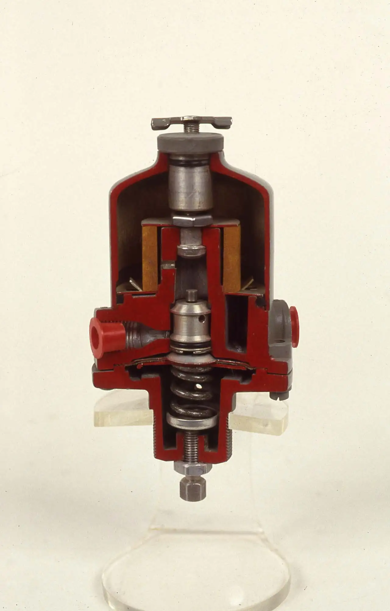
A boiler or fired heater air preheater recovers heat from the flue gas leaving the economizer or the furnace outlet and transfers it to the incoming combustion air, raising thermal efficiency by roughly one percent for every 20 to 25 deg C of air temperature rise and stabilizing flame temperature for clean combustion. The two working architectures are the rotary regenerative air preheater, a slowly turning basket matrix invented in the Ljungstrom tradition that alternately stores heat in ceramic or metal elements from the gas pass and releases it to the air pass, and the recuperative tubular or plate air heater, a stationary exchanger where heat passes through a wall continuously. Exit gas temperatures fall from the 300 to 400 deg C band toward 120 to 160 deg C, and the saved fuel pays for the hardware within a small number of years on any continuously fired unit.
Procurement engineers meet these units on utility and industrial boilers, API 560 fired heaters, recovery and waste heat applications, and retrofit programs on plants chasing efficiency mandates. The decision this page settles is which architecture fits the fuel and the plot: a rotary unit with its compact surface and leakage management, or a tubular unit with its zero leakage construction and larger footprint. The answer lands as an RFQ line set, gas and air flows, fuel sulfur and acid dew point, allowed leakage, pressure drop limits, and element or tube materials, and every chapter below feeds that line set so the preheater is bought against the boiler it serves rather than against a generic heat exchanger page. This page is the combustion air preheater authority: the feedwater economizer, which the same plants install for water side heat recovery and which explicitly does not do this duty, is covered by its own page, and the two together finish the flue gas heat recovery train.
This page treats the air preheater as a purchasing object: how rotary regenerative and recuperative tubular designs divide the duty, what leakage and X-ratio actually mean in operating numbers, how cold end corrosion is managed against the acid dew point of the fuel, and how the whole decision folds into a defensible RFQ with fan margin and cleaning strategy included. It is written for engineers who issue purchase specifications on fired equipment, not for readers who want a brochure summary.
Chapter 1 / 06
What an Air Preheater Is and What Is Being Decided
The defining act of the machine is flue gas to combustion air heat recovery on the fired side of a plant. Fuel burns with air, the flame and the heat transfer surfaces take what the process needs, and the flue gas still leaves hot enough to waste several percent of firing. An economizer picks up part of that loss into feedwater, and the air preheater picks up another part into the combustion air itself, which is the rare recovery that returns heat directly to the same fire that made it, so every kilojoule recovered is a kilojoule of fuel not purchased. Plants that install both usually put the air heater after the economizer in the gas path, taking the gas from the 250 to 350 deg C band down toward 130 to 160 deg C, with the exact floor set by the acid dew point logic described in chapter 4 rather than by hardware courage.
What is being decided in this purchase is four commitments at once. First an architecture: rotary regenerative or recuperative tubular, because that choice sets leakage behavior, plot shape, and maintenance content for decades. Second an efficiency and corrosion envelope: air temperature rise and exit gas temperature against the fuel sulfur content and the resulting acid dew point, which decides cold end materials and the need for air side preheating or bypass. Third a leakage and pressure drop allowance, because direct leakage in a rotary unit steals recovered heat back to the stack and both architectures consume fan power. Fourth a cleaning and maintainability basis, since firing fuels with ash or sulfur makes the preheater a scheduled cleaning item and the access for it belongs in the purchase. A buyer who lets any of the four be filled in later has bought a drawing.
Against its neighbors the air preheater occupies precise ground. The economizer is the water side partner and its own page already states plainly that it is not an air preheater: one recovers into feedwater, the other into combustion air, and a plant with both recovers in series. The industrial burner page covers the combustor that receives the heated air, and a burner retuned for 250 deg C air is a different combustion calculation than one on ambient air, which is why burner suppliers belong in the preheater conversation. An aftercooler on a compressor train is a different duty entirely, gas conditioning on air that will be compressed, not combustion air. HVAC energy recovery wheels share the regenerative concept with the rotary air preheater, and they appear in this page only as a selection chapter neighbor, because building ventilation duty and boiler flue gas duty live in different temperature, corrosion, and code worlds.
Standards and references frame the datasheet. Combustion air preheater practice draws on the boiler and fired heater codes the host equipment carries, with ASME Section I power boiler context and API 560 fired heater practice both touching air preheater scope, and manufacturer engineering literature from the Ljungstrom tradition onward documenting rotary leakage, X-ratio, and cold end corrosion management. Efficiency accounting follows the combustion test codes, ASME PTC 4 for steam generators, which treats air temperature rise and exit gas temperature as measured quantities in the efficiency calculation. A datasheet that quotes an efficiency gain without stating the exit gas temperature basis or the leakage allowance is a price tag, not a specification.
The station around the preheater deserves naming in the RFQ too. Heated air changes the draft balance: an induced draft fan moves the flue gas through the gas side pressure drop, a forced draft fan pushes the air side, and a plant that adds a preheater to an existing boiler usually buys fan margin or a vfd retrofit in the same project, with combustion controls retuned for the new air density. On the gas side, a flue gas analyzer and oxygen trim, in zirconia oxygen analyzer form on many plants, keeps excess air honest once the air is hot; on the air side, temperature transmitters across the preheater and a pressure transmitter reading the differential give the operating evidence. A flame detector and burner management logic on the host burner complete the safety picture, and an expansion joint isolates the duct growth. Buying the preheater without its fans and dampers scoped is how startup arguments begin.
Chapter 2 / 06
How Regenerative and Recuperative Air Heating Work
The rotary regenerative air preheater is a heat wheel. A rotor, typically 3 to 15 meters in diameter, carries baskets packed with formed heating element plates and turns slowly, about one to three revolutions per minute, between two sector shaped ducts: flue gas passes through one side of the rotor and gives up heat to the matrix, combustion air passes through the other side and takes it back a half revolution later. Surface compactness is the reward: packed element matrices pack thousands of square meters of surface into a rotor a few meters deep, which is why the architecture owns large utility boilers where a tubular battery of the same duty would not fit the plot. Gas and air are separated by sector plates and radial, axial, and circumferential seals, and because the two streams sit at different pressures, air to gas leakage through those seals is a design quantity the buyer manages rather than a defect the buyer eliminates.
Leakage is the number that decides whether a rotary preheater is worth its surface. Direct leakage flows through seal gaps from the air side, higher pressure, to the gas side, lower pressure, in proportion to the square root of the density difference and the gap area, and carryover leakage rides in the rotor matrix spaces as it passes between sectors. Design direct leakage of roughly 5 to 10 percent of air flow is normal for well maintained units, wearing upward as seals age toward 15 percent and beyond on badly maintained ones, and every percent of leakage is air that the fans moved but the fire never saw, sending heat and forced draft power straight up the stack. Seal architecture answers it: adjustable radial seals that close as the rotor warms into its mushroom shape, double or triple seal lines that interpose more restriction, and on the largest units, seal air fans pressurizing the gap. The RFQ should quote leakage at new and at guaranteed end of seal life, with the test method named.
The X-ratio is the rotary design lever most buyers have never heard of and should. It is the ratio of air side heat capacity rate to gas side heat capacity rate, and because flue gas carries more mass and moisture per unit of fuel than combustion air consumes, the gas cools through a smaller temperature span than the air heats. Moving X by recirculating hot air or trimming excess air shifts where the matrix surface spends its temperature life, and hence where the cold end corrosion risk concentrates. Recuperative tubular air heaters have no leakage by construction, air and gas separated by tube walls in a static casing, at the cost of a much larger surface volume: plain or finned tubes carry the gas inside while air flows across the bundle, or the reverse, and overall heat transfer coefficients are modest, so the battery is big, heavy, and cheaper in elements but hungrier in plot.
Heat transfer and pressure drop economics bind both architectures. Typical design leaves the air 60 to 150 deg C hotter than it entered, limited less by surface than by the stack corrosion floor and by the combustion system tolerance for hot air. Gas side pressure drop across a preheater runs commonly 10 to 25 millibar and air side 5 to 15, both charged to fan power for the life of the unit, and element profile selection in a rotary matrix, deep undulating passages for heat transfer against straighter passages for lower drop and cleanability, is exactly the trade the specification should force the vendor to state. Fouling raises both numbers over the campaign, with ash bearing fuels doubling gas side drop before cleaning in bad cases, so fan sizing belongs to the dirty end of the range with margin, not to the clean datasheet point.
Cold end corrosion is the failure mode that writes the materials page. When the fuel carries sulfur, flue gas carries sulfuric acid vapor, and any surface below the acid dew point, commonly 100 to 150 deg C depending on sulfur level and excess air, collects condensed acid that eats carbon steel and glues ash into blockage. The cold end of the preheater, the gas outlet corner of a rotary matrix or the gas outlet rows of a tubular bundle, runs closest to that floor because it meets incoming cold air. The management toolkit is standard: cold end element sections in corrosion resistant alloy, corten or duplex grades, air side preheating with a steam coil or recirculation duct that lifts the entering air temperature, bypass dampers that hold gas side wall temperatures above the dew point at low loads, and sootblowing or water washing that keeps the acid wet surface from holding ash. The buyer who does not know the fuel sulfur and the resulting dew point cannot buy a preheater, only rent an argument.
Chapter 3 / 06
Air Preheater Types, Construction, and Duty Boundaries
Within the rotary family the catalog divides by rotor support and seal architecture. The vertical shaft, top supported rotor with heating elements in circumferential compartments is the classic utility form, sector plates below and above, radial seals riding the rotor face, and a drive motor through a pinion ring. The horizontal shaft form appears on smaller industrial units and some retrofits. Bi-sector air and gas only is the standard boiler arrangement; tri-sector units add a primary air sector for pulverized coal plants, splitting the rotor between primary and secondary air, which couples the preheater to the pulverizer and dryer duty. Seal options run from single adjustable radial lines to double seals and active seal air systems, and element profiles run from high heat transfer undulating DU style plates to straighter, easier cleaning passages chosen for high ash fuels.
Tubular air preheaters divide by flow arrangement and tube material. The classic vertical spindle form passes gas down inside vertical tubes with air crossing the outside in multiple passes baffled across the bundle, and horizontal tube forms put gas outside the tubes in ducts where drainage and wash access matter more. Plain carbon steel tubes serve clean gased units; corten and small chromium additions serve the cold end on sulfur fuels; glass tubes or enameled and coated surfaces appear on the most acid aggressive low load service, and 2205 duplex appears where chloride rich fuels push past corten. Plate type recuperative air heaters, corrugated plates welded into modules, sit between tubular and rotary on compactness and share the zero leakage property. Cast iron air heaters with extended surfaces survive the oldest plants in the harshest service and remain a niche buy.
Boundaries are worth stating bluntly. This unit is combustion air heating on fired equipment, not building ventilation heat recovery, where energy recovery wheels and air side economizers under HVAC rules do smaller temperature duty with different corrosion economics, and the selection chapter only nods to that neighbor. It is not the feedwater economizer, whose page already claims the water side of the same flue gas train. It is not a process air cooler or an aftercooler on a compressor, which condition air or gas for machinery rather than for a burner, and it is not a fired heater, which makes the flue gas this machine harvests. Retrofit scope deserves the same bluntness: adding a preheater to an existing boiler changes fan duty, duct growth, burner aerodynamics, and control tuning, and a quotation that assumes none of that changes is quoting half a project. The type map below compresses the boundaries into one table.
Architecture
Typical leakage
Best duty
Avoid when
Vertical rotor regenerative, bi-sector
5 to 10 percent new, 10 to 15 worn
Large utility and industrial boilers, tight plots, high surface duty
Fuel and permit make any direct leakage unacceptable
Vertical rotor regenerative, tri-sector
As bi-sector plus PA side
Pulverized coal plants feeding pulverizer and burner air
Simple gas or oil plants with no primary air duty
Horizontal rotor regenerative
Similar class
Smaller industrial boilers and retrofit plots
Very large duties where vertical support is standard
Vertical spindle tubular
Zero by construction
Sulfur sensitive and permit sensitive plants accepting the footprint
Plot cannot fit the bundle length and access
Plate or modular recuperative
Zero by construction
Medium duties wanting compact zero leakage surface
Heavy ash fuels that prefer tube washing access
Glass or coated cold end tubular
Zero by construction
Low load, high sulfur, acid aggressive service
Mechanical risk environments for glass
Chapter 4 / 06
Key Specification Parameters
The table below decodes the datasheet lines that decide whether a quoted air preheater matches the boiler and the fuel. Each row is a purchase defining parameter; the paragraphs after the table explain what to demand and what a weak answer looks like.
Attribute
Typical range or options
What it decides
Gas flow and inlet temperature
From economizer outlet, 250 to 400 deg C typical
Surface duty, rotor or bundle size, and exit gas floor feasibility
Air flow and temperature rise
60 to 150 deg C rise typical
Efficiency gain, burner retune scope, and fan duty
Fuel sulfur and acid dew point
Dew point 100 to 150 deg C by sulfur
Cold end materials, air preheat or bypass need, washing scope
Direct leakage guarantee
5 to 10 percent new; end of seal life stated
Recovered heat kept, stack loss, and fan power on the air side
Gas side pressure drop
10 to 25 mbar clean, dirty end higher
Induced draft fan sizing and margin, plus cleaning trigger
Air side pressure drop
5 to 15 mbar
Forced draft fan duty and burner windbox pressure
Element or tube materials
CS hot end, corten or duplex cold end, glass options
Corrosion life between replacements and ash adhesion behavior
X-ratio and air preheat scheme
Steam coil, recirculation, or bypass dampers
Cold end metal temperature floor at low load
Cleaning provisions
Sootblowers, water wash nozzles and drains, access doors
Campaign length on ash bearing fuels and outage scope
Drive and rotor support
Motor and pinion drive, vertical or horizontal shaft
Maintainability, spare drive philosophy, and ceiling height
The leakage and dew point rows carry the warranty. Demand leakage quoted with its test basis, oxygen balance across the preheater measured at guarantee conditions, at new condition and at guaranteed end of seal life, because the difference between those two numbers is the efficiency the plant actually lives with between outages. On the corrosion side, demand the cold end average metal temperature calculation: the designer should show the coldest surface temperature at minimum load against the fuel sulfur dew point, and the answer, air preheat coil, recirculation, bypass, or alloy, should be priced in the quotation rather than discovered in the first winter. A quotation silent on either row is selling surface, not a preheater.
The pressure drop rows set twenty year operating cost. Fans are sized for dirty end drop with margin, and the RFQ should require clean and expected-dirty pressure drops per side at design flow, plus the cleaning interval that restores the clean number on the declared fuel. Element profile choice in rotary units is the honest trade between heat transfer and drop: undulating high performance profiles buy compactness and pay in drop and ash retention, straighter profiles wash easier. The second table below compresses the cold end management toolkit against fuel class, the way a specification meeting actually argues it.
Fuel and load profile
Cold end strategy to specify
Check before order
Natural gas, steady load
Carbon steel cold end, no preheat scheme
Confirm condensation only of water, not acid, at min load
Low sulfur oil, mixed load
Corten cold end, modest air preheat trim
Cold end metal temperature at minimum load against dew point
High sulfur oil, cycling load
Duplex or coated cold end, steam coil air preheat, bypass
Bypass control logic and washing provisions in scope
Coal, high ash
Straight profile elements, sootblowers, water wash
Dirty end pressure drop and fan margin; wash drain design
Biomass or waste derived fuel
Alloy cold end, aggressive washing, access doors
Fouling rate basis and outage cleaning scope
Chapter 5 / 06
Selection Decision Factors and RFQ Language
The decision sequence is short enough to run as a checklist in a specification meeting, and each step eliminates a class of quotations before price comparisons begin.
Fix the fuel analysis honestly, sulfur and moisture and ash, and compute the acid dew point, because that single number writes the cold end of the specification.
Set the heat recovery target from the efficiency case: design air temperature rise and exit gas temperature against the stack floor the dew point allows, priced in fuel saved per year.
Choose architecture: rotary for surface density on large or tight plot duties accepting managed leakage, tubular or plate for zero leakage on sulfur sensitive or permit sensitive plants accepting footprint.
State leakage and pressure drop guarantees with test methods and end of seal life conditions, and size the fans, induced draft fan and forced draft fan with their vfd or damper scope, on the dirty end numbers.
Specify the cold end package: materials, air preheat or recirculation scheme, bypass philosophy, and the calculation showing minimum load metal temperature against dew point.
Define cleaning and maintainability: sootblowing or washing provisions, access doors, element or tube replacement intervals on the declared fuel, and outage lift clearances.
Fix the interfaces: burner supplier review of hot air, duct and expansion joint growth, controls retune scope, and structural loads of the casing and rotor on the existing steel.
Fix the verification evidence: leakage test method, exit gas temperature and air rise measurement basis, efficiency accounting per the host test code, and performance tolerance.
Against neighboring equipment the comparison a specifier needs runs as follows, and it belongs here in the selection chapter rather than in the page title. The economizer takes the water side of the same flue gas and its own page states it is not an air preheater; a plant installing both sequences economizer first in the gas path, air preheater second. The industrial burner receives the hot air and must be retuned for its density and flame speed. An aftercooler conditions compressor air, a machinery duty, not a combustion duty. HVAC energy recovery wheels are the regenerative concept at ventilation temperatures and appear here only as a conceptual neighbor. The deaerator, the boiler feed pump, and the condensate train around the steam cycle belong to the water side story, not this one. Name the boundaries in the RFQ and the vendor quotes the right machine against the right duty.
The RFQ block should be written once and reused. A complete block reads: fuel analysis with sulfur, moisture, and ash; excess air basis; design, normal, and minimum gas flow and inlet temperature; combustion air flow with design temperature and humidity; required air temperature rise and exit gas temperature floor; acid dew point basis or the data to compute it; architecture named with rotor or bundle arrangement; leakage guarantee at new and end of seal life with test method; gas and air side pressure drop, clean and dirty, at design flow; element or tube specification including cold end materials and profiles; air preheat scheme and bypass philosophy with control basis; cleaning provisions with sootblower or wash scope and drains; fan interface duty points including vfd or damper scope; structural and duct interface loads with expansion joint allowance; instrumentation list with temperature transmitters per stream and differential pressure reading; and the performance test basis with tolerances. A quotation returned without the leakage end of life number or the cold end metal temperature calculation is incomplete at any price.
Chapter 6 / 06
Installation, Standards, Failure Modes, and Maintenance
Installation quality decides whether the guarantees survive contact with the plant. Ductwork to the preheater goes in with the expansion joints the thermal growth study called for, because a rotor casing and a tubular battery grow tens of millimeters between cold and hot and will crack welded ducts that were not designed to float. Seals are set cold with the clearance map the vendor computed for the hot rotor shape, the mushroom distortion that closes top clearances on a vertical rotor, and the first heat cycle is the calibration point for seal adjustment, not a formality. Fan commissioning follows the new duty points: a forced draft fan moving hotter lighter air and an induced draft fan absorbing the preheater drop both need their vfd or damper schedules reconfirmed, and the combustion controls, oxygen trim from the zirconia oxygen analyzer or gas analyzer, retuned against hot air density before the efficiency test.
Commissioning proves three numbers: air rise, exit gas temperature, and leakage. The acceptance test measures air and gas temperatures at design firing with the method the RFQ named, computes efficiency gain against the baseline, and reads leakage by the oxygen balance across the unit. The cold end scheme is proven at minimum load, where the bypass or air preheat control must hold metal temperature above the dew point, and the washing system is run once on water to prove drains and pitch before the first ash campaign fills it. Documentation of the as-built seal settings and the cold clearances belongs in the plant file, because every future outage resets against those numbers.
Failure modes in service follow a short and predictable list. Seal wear on rotary units raises leakage year over year, visible as climbing stack loss, falling measured air rise, and forced draft fan running harder for the same firing; the remedy is seal adjustment or replacement on a campaign the end of life guarantee sized. Cold end corrosion and fouling eat element plates and glue ash into blockage on sulfur and ash fuels, raising gas side drop and forcing load limits; the remedies are the materials and washing bought at specification, and element replacement when thinning passes the structural limit. Tubular units fail by tube wall thinning at the cold rows and by erosion at gas inlet openings on ash fuels, answered by sacrificial ferrules and tube end shields and periodic retubing of the cold rows. Drive problems on rotors, motor, coupling, and pinion, announce themselves by torque trends and by rotor posture on the thrust bearing. Sootblower faults leave localized fouling long before average drop betrays it, and washing without drained, pitched casings turns acid ash into sludge that blocks the drains instead of leaving.
Maintenance intervals scale with fuel class more than with running hours. Gas fired units on steady load run multi year seal campaigns with sootblower attention only. Sulfur oil service moves to an annual seal inspection with cold end element thickness survey on a defined sample, and coal and biomass service runs washing between outages and element management at every outage, with spare baskets or cold end modules held on site. Instrumentation calibration, the temperature transmitters that carry the efficiency calculation and the differential reading that schedules cleaning, follows the plant instrument calendar, and the gas analyzer or oxygen trim that closes the combustion loop belongs to the same schedule. Every outage produces numbers, seal gaps, element thickness, clean versus dirty pressure drop, and the file of numbers is what the next RFQ uses to tighten the next guarantee, which is how a purchasing file gets smarter instead of just older.
FAQ
How much efficiency does an air preheater actually add?
Roughly one percent of fuel for every 20 to 25 deg C of combustion air temperature rise, within the practical band of a 60 to 150 deg C rise, so a typical unit returns two to five percent of firing on a continuous boiler. The exact number depends on the exit gas temperature you allow and the fuel, and the acceptance test should measure air rise and exit gas temperature against a documented baseline rather than trust a datasheet projection.
What leakage should I accept from a rotary unit?
Five to ten percent direct leakage at new condition is normal for well engineered seals, with the guarantee also stated at end of seal life, since the plant lives at the aged number. Above roughly 15 percent, recovered heat is flowing back up the stack and the seal campaign is overdue. If the permit or the fuel makes any direct leakage unacceptable, buy the recuperative tubular or plate architecture and pay the footprint instead.
How do I control cold end corrosion on sulfur fuel?
Lift the coldest surface temperature above the acid dew point, which commonly sits between 100 and 150 deg C depending on sulfur and excess air. The toolkit is corrosion resistant cold end elements, corten or duplex, air side preheat by steam coil or recirculation, and bypass dampers at low load, with regular sootblowing or water washing to remove acid ash deposits. Demand the cold end metal temperature calculation at minimum load in the quotation.
Rotary or tubular, which do I buy?
Buy rotary when surface density and plot decide, large boilers and retrofits with little room, accepting managed leakage and seal maintenance. Buy tubular or plate when zero leakage is required by permit or economics and the plot can carry the longer casing, accepting lower compactness and, on ash fuels, tube washing access needs. Both deliver comparable air rise; leakage philosophy and footprint are the actual decision axes.
Do I need to change fans when adding a preheater?
Almost always yes in scope. The gas side absorbs the preheater pressure drop on the induced draft fan, the air side absorbs its drop plus hotter lighter air on the forced draft fan, and both need duty confirmation at dirty end conditions with margin. Many retrofits add a vfd or new impeller in the same project, and the quotation should state the interface duty points rather than assume existing fans carry it.
What is the X-ratio and why does it matter?
It is the ratio of air side to gas side heat capacity rates, and because flue gas carries more mass and moisture than the air consumed, the gas cools through a smaller span than the air heats. The X-ratio positions matrix temperatures through the rotation and therefore where the cold end corrosion risk concentrates. Designers trim it with hot air recirculation and excess air strategy, and it belongs in the design basis the vendor hands over, not in a drawer.
How is air preheater performance verified at acceptance?
By measuring air temperature rise and exit gas temperature at design firing with instruments agreed in the RFQ, computing efficiency gain against the pre retrofit baseline per the host test code, and reading rotary leakage by the oxygen balance across the unit. Tolerances on each measured quantity belong in the contract, because those three numbers, rise, exit temperature, and leakage, are the entire commercial case for the hardware.