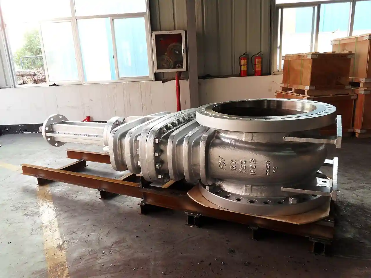
A deluge valve is a listed releasing valve that holds a fire protection pipe network dry, with open sprinklers or spray nozzles mounted along it, until a detection or release system trips it, whereupon it opens fully and floods the entire network from the water supply in seconds. The valve holds the supply pressure back with a diaphragm or clapper held closed by water pressure on a control chamber, and the release system, hydraulic, pneumatic, electrical, or a wet pilot line, drains that control chamber through a trim of priming, alarm, and emergency release piping. Sizes run 40 to 300 mm, commonly 65 to 200 mm, with listed working pressures to 12 or 17 bar family by model, and the assembly is qualified as a unit, valve body plus trim plus release panel, under UL, FM, VdS, or LPCB listings read against NFPA 13, 15, 16, and 25 practice.
Procurement engineers meet these valves wherever the hazard needs water everywhere at once: transformer and turbine bays protected by water spray under NFPA 15, aircraft hangars and flammable liquid storage with foam-water systems, loading racks, cable trays, and process units where a closed-head system would let fire outrun the sprinklers. The decision this page settles is what the valve assembly must guarantee on paper: the release logic and its supervision, the listed working pressure against the fire pump churn pressure, the reset procedure, and the inspection regime that NFPA 25 imposes on the trim. The answer lands as an RFQ line set covering system type, hazard density, valve size and listing, release method, trim arrangement, and accessories, and every chapter below feeds that line set so the system trips on the fire, not on luck.
This page treats the deluge valve as a purchasing object: how the control chamber holds the seat shut and what drains it, how diaphragm and clapper bodies differ in reset and maintenance, how release methods map to hazards, and how listings, trim, and accessory switches combine into a defensible RFQ. It is written for engineers who issue purchase specifications, not for readers who want a brochure summary.
Chapter 1 / 06
What a Deluge Valve Is and What Is Being Decided
The problem being solved distinguishes the deluge system from every other sprinkler arrangement. In a wet system, closed heads open one by one as heat fuses their elements, and the piping stays pressurized. In a deluge system, the heads are open all the time, so the piping cannot be pressurized at all, or water would run out continuously; instead, a single valve at the supply holds the whole network dry, and when it opens, water reaches every head simultaneously. That single valve therefore carries the entire releasing function of the system, which is why it is bought as a listed assembly rather than as a generic hydraulically operated valve, and why its release logic, not its pipe size, is the first line of the specification.
What is actually being decided in this purchase is four guarantees. First, release integrity: the valve must stay closed against supply pressure for years, hold its control chamber pressurized through trim and check arrangements, and never drip into a dry network that would corrode or freeze. Second, trip performance: on a valid detection signal, the valve must open fully and fast, a family of seconds, delivering the design density the hydraulic calculation assumed, and the release path that trips it must match the hazard, electric release panels with listed detectors, pneumatic or dry pilot lines where detection is thermal fusible elements, wet pilot lines where heat-responsive sprinkler elements act hydraulically. Third, supervision: every isolation and drain in the trim must report its position, because an unnoticed closed supply valve is the classic way these systems fail silently. Fourth, serviceability: the valve must reset after a trip without dismantling the body, and the trim must permit the routine NFPA 25 inspections, full flow trip tests on a scheduled basis, without cutting pipe.
Against its neighbors the deluge valve occupies deliberate ground. An isolation valve upstream, a gate valve or butterfly valve listed for fire service, shuts the supply for maintenance, and a check valve downstream of the fire pump prevents reverse flow, but neither releases anything. A preaction valve governs a system with closed heads where the design intent is double interlock protection against accidental water, a different product with different listings that appears here only as a neighboring system in the selection chapter. A solenoid valve inside the trim is the electrical actuator that drains the control chamber on panel command, a component of the deluge assembly rather than a substitute for it. The fire pump supplies the water; a deluge valve meters nothing, controls nothing in the throttling sense, and simply holds or floods. Its narrow territory is the certified hold-then-flood function, and no general purpose valve carries the listing that certifies it.
Four references organize the datasheet. NFPA 13 sets the installation rules for deluge systems as a sprinkler arrangement, and NFPA 15 governs water spray fixed systems, the transformer and equipment protection duty; NFPA 16 extends the family to foam-water systems. NFPA 25 sets the inspection, testing, and maintenance regime, including the periodic full flow trip test the trim must support. The listing itself, UL 260 or the FM approval class for deluge and preaction valves, qualifies the valve and its trim as a unit, and the manufacturer's published installation data, such as the Viking F-1 straight-through deluge valve technical data, fixes the arrangement the listing covers. A datasheet that quotes none of these is a price tag, not a specification, and a deluge assembly offered without its listed trim is not a listed assembly at all.
The RFQ should also name the station so the package checks out as a system. The water supply runs from the municipal or tank feed through the fire pump set with its churn pressure, which must not exceed the valve's listed working pressure; a pressure gauge and pressure transmitter at the valve inlet record the supply state that supervision watches. The release system connects through its listed panel or pilot lines, and a flow switch or pressure switch on the alarm line reports the trip to the fire alarm system. Around the valve, the supply isolation gate or butterfly valve carries a supervisory switch, a Y strainer protects the priming line where water quality demands it, and the drain, test, and inspector's test connections complete the trim. In the protected area, flame detector and combustible gas detector inputs can drive electric release where the hazard justifies them, and an eye wash station near the risk area belongs to the same safety package purchase. Stating the whole station in the RFQ lets one supplier check listing compatibility, pipe fitting orientation, and alarm interfaces in a single pass.
Chapter 2 / 06
How the Control Chamber Holds and Releases
The holding mechanism is a differential area trick used in two constructions. In the diaphragm valve, a flexible reinforced diaphragm spans the top of the valve body with supply pressure admitted to its upper side through a restricted priming line; the diaphragm bears on a seat or clapper with a pressure-effective area larger than the inlet opening, so modest pressure on top holds the full supply pressure below. In the clapper valve, a hinged clapper with a rubber seat is held against its seat by a latch or by a piston loaded from the control chamber, arranged so control pressure keeps the latch engaged. In both constructions the system is normally held, needing pressure to stay closed rather than to open, which is the safety logic: a broken trim line drains the control chamber and the valve trips, failing toward water rather than toward silence.
Release is the controlled un-holding of that chamber. The priming line constantly feeds control pressure through a restriction, and the release path drains it faster than it can be resupplied. A hydraulic wet pilot line, essentially a small piping loop charged with pressure and closed by heat-responsive pilot sprinklers, drains the chamber through the pilot head when a pilot element fuses, purely hydraulic tripping with no electricity. A pneumatic dry pilot line holds compressed air against a differential latch; a fused pilot vents the air and releases. Electric release uses listed detection, heat, smoke, flame, or gas detectors, feeding a listed releasing panel that energizes a solenoid drain valve in the trim, the arrangement that permits the detection philosophy to match the hazard rather than the plumbing. Manual emergency release, a lever or ball valve that drains the chamber directly, exists on every trim and is the operator's trip of last resort.
Trim is where the engineering lives. The priming line carries the restriction, often with a Y strainer where the supply water carries scale, and a check arrangement isolates the control chamber from supply surges so a pressure wave cannot slam the valve open or closed. The alarm line connects the valve's internals to the water motor gong or the pressure switch that reports flow to the panel. The drain and test connections permit the inspector's test, a small orifice that simulates a trip condition on some arrangements, and the emergency release permits manual trip; small bore drain and vent duties inside the station use a globe valve or needle hardware, while the main isolation stays a listed gate or butterfly pattern. Modular trim, pre-piped and listed as an arrangement, arrives as a kit bolted to the valve, replacing the older drawn-assembly approach where each instrument was piped on site and the listing depended on faithful reproduction of the data sheet. The reset procedure follows the construction: diaphragm valves reset by closing the drain and re-pressurizing the chamber through the priming line with the external reset lever held, some models latching automatically; clapper valves reset by opening the body and re-latching the clapper by hand on the older designs, while modern latching trims re-latch through an external station without dismantling.
Trip time and full opening are performance behaviors the listing exercises. The release path must drain the control volume faster than the restriction refills it, and the published flow diagrams for each model define the orifice sizes that make this true at the minimum supply pressure; a trim assembled with a wrong restriction or a partly closed manual valve can hover near balance and deliver a sluggish, partial opening that starves the far heads of the design density. Electric release adds the panel response time, detector delay settings, and solenoid operation into the sequence, which is why commissioning trip tests are logged with time to full flow. A worked example fixes the arithmetic: a transformer bay protected at 10.2 L/min per square meter over 200 square meters needs 2,040 L/min at the valve, plus hose stream allowance; a 150 mm straight-through deluge valve with listed working pressure above the fire pump churn delivers that with margin, while a trim whose restriction has been replaced with an oversized orifice might never build enough differential to reseat, a finding that belongs at commissioning, not at the fire.
Water quality runs through every failure story. The priming restriction is small; scale and sediment choke it, and the control chamber slowly loses pressure, with the valve creeping toward an unintended trip or failing to reseat after tests. Supplies from static tanks or rivers strainer the priming line as standard practice, and NFPA 25 annual internal inspections look exactly at this chamber and strainer. Freeze protection in the same family: the dry network above the valve holds no water by design, but the trim itself holds water and needs a heated valve house where the climate demands it, because a frozen priming line is a valve that cannot reseat and sometimes cannot trip. These behaviors explain the inspection regime and belong in the specification as operating assumptions rather than as fine print in a manual nobody reads.
Chapter 3 / 06
Types, Construction, and Duty Boundaries
Three axes organize the catalogs. The first is the closure construction: diaphragm valves, with the reinforced diaphragm as the holding element, dominate modern designs for their external reset and simple trim; clapper valves, with a hinged clapper and rubber seat, remain common in larger sizes and older installed base, with some designs re-latched externally and others needing body access. The second is the body pattern: straight-through designs, with the inlet and outlet in line, like the Viking F-1 in 65 through 200 mm, suit compact valve rooms; angle designs turn the flow 90 degrees and combine the valve with the elevation change many valve houses need. The third is the release method: hydraulic wet pilot, pneumatic dry pilot, electric solenoid from a releasing panel, and manual emergency, all of which hang on the same trim interface, so the release philosophy can be chosen per hazard without changing the body.
Within those axes, construction choices carry the warranty. Body materials are ductile iron or bronze fitted, epoxy coated internally for water quality, with flange drilling per the regional standard, ASME or EN, matched to the fire main; listed working pressures run to 12 bar family with higher ratings to 17 bar on some models, and the selection rule is simple, the fire pump churn pressure plus static head must sit below the listed rating with margin. Diaphragms and seats are synthetic rubber compounds qualified with the listing, nitrile or EPDM family by model, and replacing them with unlisted equivalents voids the arrangement. Trim components, the priming restriction, the check arrangements, the drain and emergency release, the solenoid interface, arrive as the listed kit, and the listing covers the kit's exact contents; substituting a ball valve for a listed drain valve because the kit part is backordered is the most common way a listed system quietly becomes an unlisted one.
Boundaries against neighboring systems are worth stating bluntly. This valve never substitutes for a preaction valve: a preaction system feeds closed heads and exists to prevent accidental water discharge into water sensitive spaces, with the valve supervising the piping with air or nitrogen and requiring both detection and head operation, double interlock, before water moves; a deluge valve feeds open heads and floods on detection alone. A dry pipe valve, the heating family product, also feeds closed heads but exists to protect freezing spaces with a dry network and its own acceleration hardware. A water spray system under NFPA 15 uses deluge valves but with nozzles aimed at specific equipment rather than area sprinklers, and foam-water systems under NFPA 16 add proportioning between supply and valve or downstream. The boundaries matter commercially because the trims, listings, and hydraulic assumptions differ, and a supplier who quotes a preaction trim for a deluge duty, or the reverse, has not read the hazard.
The duty map below consolidates the boundaries into one table a specifier can scan before writing the RFQ; it pairs common hazards with the construction and release that survives them and the choices that generate callbacks.
Hazard
Construction and release to specify
Choice that generates callbacks
Transformer bay, water spray NFPA 15
150 to 200 mm diaphragm, electric release from listed panel
Wet pilot line where detectors define the design
Aircraft hangar floor nozzles
200 to 300 mm straight-through, electric or pneumatic release
Trim rating below fire pump churn pressure
Flammable liquid loading rack
Diaphragm with foam-water trim per NFPA 16
Deluge trim quoted for a foam-water duty
Process unit, explosion driven detection
Electric release, flame detector inputs, supervised trim
Unsupervised isolation valves in the station
Cable cellar or vault, water sensitive
Preaction system, not a deluge valve
Deluge flooding a space that needed interlock
Freezing climate valve house
Heated enclosure or dry pilot with antifreeze provision
Silent substitution of diaphragm model without hydraulic review
Chapter 4 / 06
Key Specification Parameters
The table below decodes the datasheet lines that decide whether a quoted assembly matches the hazard. Each row is a purchase defining parameter; the paragraphs after the table explain what to demand and what a weak answer looks like.
Attribute
Typical range or options
What it decides
Nominal size
40 to 300 mm; common 65, 100, 150, 200
Flow at design density and the hydraulic calculation basis
The listed pressure row deserves a paragraph of its own because it is the row that quietly voids assemblies. The rating that matters is the maximum supply pressure with the fire pump at churn, no flow, maximum shutoff head, plus the static elevation head, and the RFQ should force both numbers into one statement: supply pressure at the valve, and listed rating of the assembly. A fire pump upgrade five years after installation is the classic way an assembly silently finds itself over rating; writing the pump churn into the valve datasheet makes the next engineer check the pair together. The same logic applies in reverse to the release panel and solenoid, whose listed voltage and response behavior are part of the assembly's qualification.
The trim and supervision rows decide whether the system can be operated and inspected as designed. Demand the trim arrangement drawing with the kit contents listed, the restriction orifices identified, and the test connections located; a trim without an inspector's test connection converts the NFPA 25 full flow trip test into an improvised exercise. Supervisory switches on the supply isolation and drain valves, wired to the panel, are the difference between a system that announces its own disablement and one that fails silently. The comparison table below compresses the evidence checks into the form a specification meeting can argue from.
The environmental row closes the specification. A dry network with open heads holds no standing water, but the trim and control chamber do, so an unheated valve house in a freezing climate needs heat tracing or a heated enclosure written into the station scope, and the drain arrangements need to clear the trim after every test. Dirty supplies need the strainer and an inspection scope sized to the water. The quotation that quotes the valve and leaves the valve house, heat, drainage, and panel integration as site exercises is not a complete quotation.
Chapter 5 / 06
Selection Decision Factors and RFQ Language
The decision sequence is short enough to run as a checklist in a specification meeting, and each step eliminates a class of quotations before price comparisons begin.
Fix the hazard and design basis first: water spray to equipment under NFPA 15, area deluge under NFPA 13, foam-water under NFPA 16, with the design density and area of operation from the hazard analysis.
Compute the flow and head at the valve, then pick the size: the valve K factor or flow data, not the pipe diameter, decides whether 150 or 200 mm carries the calculated demand.
Check the pressure fit: fire pump churn plus static head against the listed working pressure, with margin, before anything else is compared.
Choose the closure construction: diaphragm for external reset and simpler trim on most new stations, clapper where the installed base or the size argues for it, with the reset procedure read before purchase.
Match the release method to the detection philosophy: electric release where listed detectors define the trip, wet pilot for purely thermal hydraulic logic, dry pilot where the pilot line must stay dry.
Specify the trim as a listed kit by drawing and part list, with the inspector's test, drain, strainer where water demands, and emergency release located.
Add the station hardware: supervised isolation valve, pressure gauges and transmitter points, alarm pressure switch and flow switch interfaces, and releasing panel compatibility stated by model.
Fix the regime in the purchase: NFPA 25 owner obligations, full flow trip test interval, and the spare parts, diaphragm, seat, solenoid, restriction orifices, held against that regime.
Against neighboring valve types, the comparison a specifier actually needs runs as follows, and it belongs here in the selection chapter rather than in the page title. A preaction valve suits water sensitive spaces with closed heads and interlock logic; buying it for an open head hazard wastes the interlock and under-discharges. A dry pipe valve suits freezing spaces with closed heads; it accelerates air release rather than flooding on detection. A gate valve or butterfly valve isolates the station and supervises its own position but releases nothing. A solenoid valve is a trim component, the electric drain of the control chamber, never the barrier itself. The deluge valve wins exactly when open heads must all flow at once on a valid detection, and every other product in the fire valve family fails that sentence somewhere. Choose the assembly the hazard analysis demands, not the valve a distributor has on the shelf.
The application map below turns that comparison into a table the project file can carry.
150 to 200 mm diaphragm, electric release, NFPA 15 nozzles
Detection zone map against spray coverage
Hangar or large bay floor system
200 to 300 mm straight-through, supervised trim
Churn pressure against listed rating
Foam-water loading terminal
Deluge with foam-water trim and proportioner interface
Proportioner location relative to valve
LPG or gas storage water curtains
Electric release driven by gas or flame detection
Panel loop and detector listing compatibility
Conveyor or cable gallery spray
Angle pattern with elevation change, strained priming
Test drainage routing in the gallery
Replacing a 30 year old clapper
Like-for-like listed body and trim, hydraulic review
Supply pressure growth since original install
The RFQ block should be written once and reused. A complete block reads: system type and governing standard, deluge, water spray, or foam-water; hazard, design density, and area of operation; calculated flow and required pressure at the valve; nominal size, body pattern, and closure construction; listed working pressure against the stated supply, fire pump churn plus static; release method with the detection philosophy named, wet pilot, dry pilot, or electric release from a stated panel model; trim as the listed kit with drawing reference, priming strainer where water quality demands, inspector's test, main drain, and emergency release; alarm interfaces, pressure switch and flow switch contacts to the fire alarm system; supervisory switches on every isolation and drain; materials, coating, and elastomer compound as listed; environmental provisions, heated enclosure or dry trim arrangement for freezing sites; listing marks required, UL, FM, VdS, LPCB, per the authority; and the NFPA 25 test regime with the spare parts list priced as part of the assembly. A quotation returned without the trim drawing, the pressure fit statement, or the panel compatibility line is incomplete at any price.
Chapter 6 / 06
Installation, Standards, Failure Modes, and Maintenance
Installation quality decides whether the assembly trips as listed. Mount the valve with the trim exactly per the arrangement drawing, restriction orifices installed and the listed kit parts unaltered, because the listing covers the assembly as drawn; set the supply isolation gate valve or butterfly valve upstream with its supervisory switch wired, and keep a straight run into the valve so the internal pattern the listing assumed is preserved. Pitch the dry network to drain at low points with listed drains, since a wet pocket in an open head system is a corrosion and freeze hazard that reports itself only at the trip test. Pipe the drain and test connections to a location that can accept full flow, because the NFPA 25 trip test opens the valve completely, and a test that cannot be drained cannot be performed. The releasing panel integration, detector zones, solenoid circuit, and alarm receiving, is commissioned as one system with the valve, not as two trades meeting at a terminal strip.
Commissioning practice proves the trip, not just the pressure. With the isolation valve closed and the test drain arranged, perform the trip by each release path in turn: manual emergency release, then the pilot or electric path, logging time to full flow and the alarm switch operation. Verify reseat and reset through the written procedure, diaphragm reset station or clapper re-latch, and confirm the control chamber rebuilds pressure against the restriction with no creep into the network. Prove the supervision by operating each supervised valve and confirming the panel announces it, and document the inspector's test flow against the calculation. The file that leaves commissioning, trip times, alarm operation, reset behavior, and the trim drawing as built, is the baseline every later NFPA 25 test is compared against.
The standards set the verification frame. NFPA 13, 15, and 16 govern the system designs the valve serves; NFPA 25 governs the inspection, testing, and maintenance regime, weekly and monthly visual checks, the annual partial flow and main drain tests, and the periodic full flow trip test at the interval the standard and the authority set, three years common practice, five for some supervised arrangements with documentation. The listing standards, UL 260 family and the FM approvals class, qualify the valve and trim as a unit, and the manufacturer data sheets, such as the Viking F-1 straight-through deluge technical data, fix the arrangements the listing covers. A specification that cites the listing and the NFPA regime by name transfers the burden of proof to the supplier, which is where it belongs.
Failure modes in service follow a short and predictable list. Control chamber leakage: a worn diaphragm or seat lets chamber pressure decay, the valve weeps into the dry network or creeps toward unintended trip, and the weekly gauge check catches it as falling control pressure; the fix is the listed elastomer kit on the inspection schedule. Restriction blockage: scale or sediment chokes the priming orifice, the chamber cannot rebuild, and the valve fails to reseat after tests or trips spuriously on supply dips; the strainer and the annual internal inspection exist for exactly this. Corrosion of the dry network: open head piping holds moist air, and unlined galvanized or poorly drained runs scale and pit until a trip test plugs heads, the argument for listed internal inspection scope on aging systems. Solenoid and panel faults: the electric release path fails silent, addressed by panel supervision circuits and end of line monitoring rather than by valve hardware. Trim freeze: an unheated house turns the wet trim into a block that cannot trip or cannot reseat, prevented by the heated enclosure the station scope should have bought. Misassembled trim after maintenance: an orifice or check replaced incorrectly leaves the assembly unlisted and misbehaving, prevented by kit discipline and the as built drawing kept current.
Maintenance intervals scale with supply quality and climate more than with valve size. The weekly and monthly NFPA 25 visual checks read the gauges and the supervision panel; the annual service exercises the main drain, reads the restriction and strainer condition, and tests alarm and supervisory switches; and the full flow trip test at its scheduled interval proves the whole releasing chain, with the elastomer kit and orifice set held as priced spares so the test never waits on procurement. Every trip test, intended or accidental, is a data point: time to full flow, reseat pressure, alarm sequence, logged against the commissioning baseline. None of these checks costs a tenth of one fire that outran a valve that failed to open, and every one of them produces a number the next RFQ can use, which is how a purchasing file gets smarter instead of just older.
FAQ
How does a deluge valve differ from a preaction valve?
A deluge valve feeds open sprinklers or nozzles and floods the entire network on a valid detection signal alone; a preaction valve feeds closed heads and interlocks water admission on both detection and head operation, existing to protect water sensitive spaces from accidental discharge. The trims, listings, and hydraulic assumptions differ, so the hazard analysis, not price or availability, decides which one is quoted.
Which release method should I choose?
Electric release from a listed panel suits hazards where the detection philosophy needs defined detectors, heat, smoke, flame, or gas, and where zoned or cross-zoned tripping is wanted. Wet pilot lines give purely hydraulic thermal tripping with no power; dry pilots suit pilot runs that cannot hold water. Manual emergency release exists on every trim as the operator's last resort, and every path chosen should still be trip tested at commissioning.
Diaphragm or clapper construction, which is better?
Diaphragm designs dominate modern stations for their external reset and simpler listed trim, re-pressurizing the control chamber through the priming line without opening the body. Clapper designs hold their own at larger sizes and across the long installed base, with some re-latching externally and older designs needing body access to reset. Read the reset procedure before purchase, because reset effort drives the cost of every trip test for the life of the station.
What listings and standards apply?
The valve and its trim are qualified as a unit under listing standards such as UL 260 family or FM approvals, with VdS and LPCB marks where the authority requires them. The systems they serve are governed by NFPA 13 for deluge sprinkler systems, NFPA 15 for water spray, and NFPA 16 for foam-water, while NFPA 25 sets the inspection, testing, and maintenance regime including the periodic full flow trip test.
Can the valve reset without dismantling?
Most modern diaphragm valves reset externally: close the drain, hold the reset lever or station, and let the priming restriction rebuild control chamber pressure until the differential holds the seat. Clapper valves vary, with newer designs re-latching through an external station and older ones requiring the body to be opened to re-latch by hand. The reset procedure belongs in the written operations file and is exercised at every trip test.
Does water supply quality matter?
Yes, chiefly through the priming restriction and the control chamber. Scale and sediment choke the small orifices, leaving the chamber unable to rebuild, with slow resets, spurious trips, or creep into the dry network as symptoms. Strained priming lines on static or river supplies and the NFPA 25 annual internal inspection of chamber and strainer are the standing countermeasures, and uncoated bodies on poor water shorten elastomer and seat life as well.
How do I confirm the valve rating fits my fire pump?
Compare the assembly's listed working pressure against the maximum supply pressure at the valve: fire pump churn, the no-flow shutoff head, plus static elevation head, not the rated working point. A pump upgrade years after installation is the classic way an assembly silently ends up over rating, so the RFQ should state the supply pressure basis on the valve line and force the pair to be checked together whenever the pump scope changes.