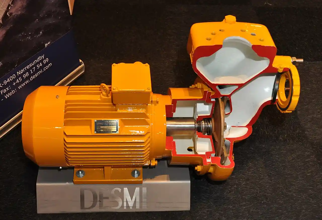
A fire pump is a centrifugal pump manufactured, tested, and listed specifically for fire protection service: built under UL 448 or approved under FM class 1319, installed per NFPA 20, and driven through a listed controller that starts it automatically on pressure drop. The same machine is often called a fire water pump or an NFPA 20 fire pump in specifications, and all three names point at one legal object: a pump whose performance curve has been certified by witnessed factory test, whose materials and construction are audited in production, and whose installation is inspected against a code. An ordinary industrial pump painted red is none of those things and does not satisfy the code.
Procurement engineers meet these pumps on high rise towers, warehouses, campuses, and industrial sites where street main pressure cannot meet system demand. The decision this page settles is narrow and practical: which configuration, horizontal split case, end suction, inline, vertical turbine, or horizontal multistage, matches the suction source and the demand; which driver, electric or diesel, matches the power reliability; and how controller, jockey pump, sensing lines, and valve train combine into a package that passes acceptance the first time. The answer lands as an RFQ line set, and every chapter below feeds that line set.
This page treats the fire pump as a purchasing object: what the UL 448 listing actually certifies, how the 100 percent and 150 percent curve points govern selection, which configuration fits which suction source, how diesel and electric drivers and their controllers are coordinated, and how the whole package is specified so it passes the NFPA 25 acceptance test. It is written for engineers who issue purchase specifications, not for readers who want a brochure summary.
Chapter 1 / 06
What a Fire Pump Is and What Is Being Decided
Start with what the listing buys. A pump listed to UL 448 has been through witnessed hydrostatic and performance testing, with the manufacturer's curve certified at defined flow points and production samples audited thereafter. FM approval to class 1319 carries an equivalent third party audit chain. NFPA 20 then governs installation: suction arrangements, controller settings, valve train, room provisions, and driver support systems. The buyer is not purchasing a centrifugal pump alone; the buyer is purchasing certified hydraulic performance, a listed controller, a driver with its own support systems, and a package of valves and instruments that must all be correct for the acceptance test to pass.
The performance obligation is fixed in three points. At rated flow, which is 100 percent, the pump must deliver its rated head. At 150 percent of rated flow, it must still deliver not less than 65 percent of rated head. At churn, which is zero flow, the head must not exceed 140 percent of rated. These numbers are not aspirations; the vendor factory certified curve must demonstrate them, and the field acceptance test rechecks them. A process buyer used to picking a pump at its best efficiency point has to change habits here: the fire pump is bought against system demand calculated in the hydraulic analysis, and its worth is defined by the certified curve, not by an efficiency figure.
What is actually being decided in this purchase has four parts. First, configuration: horizontal split case, end suction, inline, vertical turbine, or horizontal multistage, chosen mostly by suction source and floor space. Second, driver: electric motor at constant or listed variable speed, or diesel engine with fuel, cooling, exhaust, and battery systems sized per NFPA 20. Third, controller coordination: a UL 218 listed fire pump controller, its pressure sensing cascade, power transfer arrangements under NFPA 70 Article 695, and alarm supervision to the fire alarm control panel. Fourth, the hydraulic package: jockey pump, main relief and circulation relief valves, air release, and the supervised valve train on suction and discharge.
The boundary against passive neighbors is worth drawing early so the RFQ scope stays honest. A fire hydrant is a distribution fixture: it exposes municipal pressure and flow at a street location, and the flow test data taken at a fire hydrant is exactly what tells you whether a fire pump is needed at all. A fire extinguisher is first aid response, carried by a person, with no hydraulic duty. Site utility machines sit just as far from the fire duty: a submersible pump in a drainage sump and a sewage pump at a lift station both move water reliably, but neither carries a listing and neither has any place in the certified fire supply path. Gas fire suppression and sprinkler systems sit on the discharge side of the strategy: the sprinkler system consumes the pump's flow through its heads, and a gas fire suppression system protects enclosed hazards, sometimes including the pump room itself, without using pump water. The fire pump exists to convert an unreliable supply pressure into a certified system pressure, and nothing else on the site does that job.
The standards roster for the specification is short and every line can be named in the RFQ. NFPA 20 fixes installation of stationary pumps. NFPA 25 fixes the inspection, testing, and maintenance regime that follows acceptance. NFPA 70 Article 695 governs the power wiring, including the supply tap arrangement and the transfer between normal and emergency power. UL 448 covers the pump listing, UL 218 the electric controller listing, and UL 1247 the diesel engine power assembly. Factory performance testing is accepted under the pump maker's standard with reference to ANSI/HI 14.6 or ISO 9906 test codes where the contract demands a named acceptance grade. A datasheet that names none of these is a price tag, not a specification.
Finally, understand the package as a supervised system. The jockey pump, a small centrifugal pump that runs weekly if not daily, holds system pressure so the main pump does not start on minor leaks. Pressure sensing lines, traditionally 1/2 inch copper with listed pressure switch devices and increasingly pressure transmitter based, watch the system and start the cascade. Every start, every trip, every controller fault reports to the fire alarm control panel. When the specification is written, each of those monitoring points is a line item, because the acceptance inspector will test every one of them, and the RFQ is the cheapest place to get them right.
Chapter 2 / 06
How the Certified Curve Governs the Purchase
Read the curve from three anchor points. Churn, zero flow, sets the top: not more than 140 percent of rated head, because higher churn pressures stress piping and hose lines and can force pressure reducing stations into floors that never needed them. The rated point, 100 percent flow at rated head, is the contractual duty from the hydraulic calculation. The 150 percent point, at not less than 65 percent of rated head, proves the pump can be driven past its rating without collapse; fire demand is not a precise number, and the overage capacity is a safety margin written into the listing. Between churn and rated flow the curve must rise continuously toward shutoff, with no dips that could let the pump hunt or the system pressure sag.
Certification is a factory activity with witnesses. The manufacturer runs the pump at churn, rated, and a minimum of five additional points out to at least 150 percent of rated flow, and the resulting curve, signed and specific to the pump serial or at minimum the model and trim, is the curve of record. UL 448 listing rests on that test discipline. The field acceptance test later in chapter 6 rechecks rated and 150 percent against the factory curve, so the RFQ should demand the certified curve sheet with the quotation, not after the purchase order. A vendor who quotes from a generic family curve is asking the buyer to accept an unverified promise.
Suction design decides whether the certified curve can be reproduced in the field. NFPA 20 practice keeps suction velocity at or below 15 ft/s at 150 percent of rated flow and discharge velocity at or below 20 ft/s. Positive suction pressure is preferred for every horizontal configuration: flooded suction from a municipal connection with adequate residual pressure, or from a storage tank elevated or close enough to deliver it. On horizontal suction lines, concentric reducers are used so no air pocket forms on top of the reducer; an eccentric reducer installed flat side down collects air precisely where the pump inlet must not receive it. Elbows on the suction flange, particularly vertical turbines fed through poorly shaped pits, distort the inlet velocity profile and cost head.
Air management is a real acceptance risk. A horizontal split case pump is not a self priming pump: it does not pull water up from a dry source, and it must be vented at start. Each casing high point carries an automatic air release valve, a small brass device that lets trapped air escape as the casing fills and reseats when water arrives. On vertical turbines the same logic scales up: the pump can air lock on start if column and bowl air has no path out, and the air release provision plus a correct lubrication water sequence is what keeps the first start of the inspection test from becoming a churn against a vapor bound column.
Pressure maintenance is staged. The jockey pump, typically a small packaged unit, is set to start at a pressure about 10 psi above the fire pump start pressure, so minor system leakage is absorbed by a machine sized for it. A pressure switch on the sensing line has historically performed this duty; modern controllers often accept a pressure transmitter with programmable setpoints, which simplifies the cascade and adds trending. The cascade must be explicit in the RFQ: jockey start, jockey stop, main pump start, and, where a diesel driver serves, its own pressure recorder and sequential settings, all listed and all supervised. A mis staged cascade produces either churn starts that wear the main pump or a system that sags below the start point without response.
Verification closes the loop. The field acceptance test runs the pump at churn, rated, and 150 percent through either a hose valve test header or a permanently installed listed flow meter in a bypass. Water supply capacity itself is documented by flow testing the municipal grid, typically through a fire hydrant flow test with residual readings at a second hydrant, because a certified pump on an inadequate supply still fails the system demand. The annual ITM flow test under NFPA 25 repeats the three point check and trends the curve; a pump whose delivery has decayed more than the tolerance band gets pulled and examined long before the next emergency finds it out.
Chapter 3 / 06
Configurations, Drivers, and Duty Boundaries
The horizontal split case is the default of the industry and the most serviced machine in the fleet. The casing splits on the shaft centerline, exposing the rotating assembly without disturbing piping, suction arrives on axis, and the design self vents through the casing top when the air release is fitted. Ratings commonly span the 250 to 5000 gpm classes at heads that cover most commercial and industrial systems. Its costs are honest ones: it wants floor area, a solid house, and a flooded suction arrangement or a very reliable supply pressure.
The end suction configuration compresses the same duty into a single casing entry. It costs less, occupies less, and serves the smaller ratings where a split case is waste. The inline family goes further: horizontal and vertical inline units mount directly in the riser, sharing the system piping as their own support, which is why tower retrofits and packed plant rooms buy them. The penalty is maintenance access and, on vertical inline units, motor thrust bearing duty that must be verified against the motor maker's vertical mount rating rather than assumed from the horizontal catalog sheet.
The vertical turbine configuration exists for the suction sources the horizontal world cannot reach. Drawing from a wet pit, a suction tank, or a below grade source, the vertical turbine pump lifts through its column and bowl assembly, with multistage bowls stacking head in series for deep settings or high system pressure. It saves the pump house almost entirely: only the discharge head and motor sit above the slab. The engineering obligations travel with it: pit design must avoid vortices and vortex induced air entrainment, the air release provision is mandatory, and bowl wear rings in the wet environment set the maintenance cycle.
High rise service with its long discharge columns and heavy standpipe demand pushes past single stage economics, and the horizontal multistage pump takes that duty: several impellers in series on one shaft, certified on the same 100 and 150 percent discipline, with a churn pressure the floor stations can actually use. Where calculated floor pressures exceed what fittings and hose stations tolerate, the building design adds listed pressure reducing valve stations at floor levels rather than begging the pump to flatten its curve. The multistage pump is also the configuration of choice where a system demands high head at modest flow, the same hydraulic corner occupied in general industry by other machine families compared in chapter 5.
Drivers split into two families with different support systems. The electric motor at constant speed is the simplest listed package; where the system wants controlled pressure, listed variable speed controllers with pressure transmitter feedback flatten the effective delivery and reduce the need for main relief action. The diesel engine is the independence choice, specified where power reliability is doubted or mandated. NFPA 20 sizes its fuel tank at 1 gal per horsepower plus 5 percent, with no less than 8 hours of supply at rated load, requires engine driven or city water cooling loops, routes exhaust safely out of the room, and mandates two batteries with a listed charger. The engine controller is listed for fire service in its own right, and the whole engine package follows UL 1247 discipline.
Controllers are the brain of the package and a line item buyers under specify. The electric fire pump controller is listed to UL 218; it starts the pump on pressure drop, on manual demand, and in weekly churn test sequences, and it supervises its own power. Under NFPA 70 Article 695 the supply is arranged for reliability: the connection is tapped ahead of the main switch where the arrangement permits, or fed through a listed transfer switch between normal and on site emergency power. Every relevant event reports to the fire alarm control panel: pump running, power available, phase reversal, controller trouble. The table below compresses the configuration decision.
Configuration
Typical rated flow class
Suction arrangement
Where it is specified
Watch items
Horizontal split case
250 to 5000 gpm
Flooded suction, tank or strong main
Warehouses, plants, campus loops
Floor area; venting at casing high point
End suction
100 to 750 gpm typical
Flooded suction preferred
Small systems, remote pump rooms
Bearing load at high churn; access space
Inline, horizontal or vertical
100 to 1500 gpm typical
In line with the riser
Tower retrofits, tight rooms
Motor vertical thrust rating; piping loads
Vertical turbine
250 to 5000 gpm
Wet pit or suction tank
Tank fed sites, below grade water
Pit vortex and air entrainment; air release
Horizontal multistage
100 to 1000 gpm at high head
Flooded suction preferred
High rise standpipe and sprinkler supply
Churn pressure vs floor station ratings
Chapter 4 / 06
Key Specification Parameters
The table below decodes the datasheet lines that decide whether a quoted package matches the code duty. Each row is purchase defining; the paragraphs after it explain what to demand and what a weak answer looks like.
Attribute
Typical range or requirement
What it decides
Rated flow and head
From hydraulic calc, e.g. 1000 gpm at 120 psi
The contractual duty point of the certified curve
Curve points
100 percent at rated; 150 percent at 65 percent or more; churn at 140 percent or less
Listing compliance and the acceptance test pass band
Listing scope
UL 448 or FM class 1319, controller UL 218, diesel drive UL 1247
Code acceptance of pump, controller, and engine package
Configuration
Split case, end suction, inline, vertical turbine, multistage
Cast iron casing, bronze fitted, all bronze impeller, 316 shaft
Corrosion life in wet standpipe and test flow service
Velocity caps
Suction 15 ft/s, discharge 20 ft/s at 150 percent flow
Pipe sizing and flange schedule of the connected train
Driver and support
Electric or diesel; diesel tank 1 gal per hp plus 5 percent, 8 h supply, dual batteries
Start reliability under the credible worst power event
Controller
UL 218 listed, weekly churn timer, supervision to the panel
Cascade settings, transfer switching, event reporting
Jockey pump
Set about 10 psi above main start; sized for system leakage
Prevention of churn starts of the main pump
Test provision
Hose valve test header or listed flow meter bypass
Field verification at churn, rated, and 150 percent
The materials row reflects listing practice rather than a free metallurgy choice. The standard construction is bronze fitted cast iron with a 316 stainless shaft; larger and premium units move to all bronze impellers for corrosion margin in systems that see months of standing water between tests. The casing hydrostatic test is part of the UL 448 discipline. Buyers sometimes ask for a 316 casing on corrosive supplies, and some listing configurations allow it, but the request belongs in the RFQ where the manufacturer can answer against the actual listing scope rather than at delivery against a certifier's rejection.
The valve train is a fixed choreography and the RFQ should restate it in order. Suction side: an outside stem and yoke gate valve, supervised open, giving positive isolation. Discharge side, in flow order: a listed check valve, commonly a swing check valve pattern with indicator post or center post visibility, then a listed indicating control valve, either an OS&Y gate valve or a supervised butterfly valve, closed only for maintenance. No valve is permitted between the pump discharge casing and the main relief valve path where one is required. The check valve exists so the pump does not spin backward from system pressure and so the jockey pump does not feed backwards through an idle main.
Relief and cooling devices protect the machine against its own certifiable duty. The circulation relief valve opens at churn to push a cooling trickle through the casing, sized in the small tens of gpm class, and the casing relief valve protects closed sections against thermal expansion during churn. On listed variable speed packages and on high churn systems, the main relief valve dumps excess discharge pressure at churn to a visible funnel or drain; its setting is a commissioning record. The automatic air release valve at the casing high point has already earned its paragraph in chapter 2, and its maintenance is an inspection line, because a stuck air release is the first step toward an air locked start.
Sensing and instrumentation close the package. Sensing lines are 1/2 inch copper or brass, protected and drained, with listed devices; diesel installations require two independent sensing lines so a single blockage cannot blind the cascade. The traditional device is the listed pressure switch, one per stage; controllers increasingly accept a pressure transmitter with programmable stages, and either is acceptable to the code when listed. The jockey pump takes its own pressure switch. The one place a Y strainer belongs on a fire package is the small bore service, the jockey suction or the diesel cooling loop; the main suction never receives a strainer, because an obstructed fire water supply is a worse failure than a scratched impeller. The component schedule below consolidates the train.
1/2 in copper; listed pressure switch or transmitter; two lines for diesel
Test provision
Acceptance and annual flow testing
Hose valve test header or listed flow meter bypass
Chapter 5 / 06
Selection Decision Factors and RFQ Language
The decision sequence below runs as a checklist in a specification meeting, and each step eliminates a class of trouble before quotations are compared.
Fix the demand from the hydraulic calculation: system flow and the pressure required at the demand point, with the overage margin the 150 percent point will cover.
Document the supply: static and residual pressures from a hydrant flow test, or tank capacity and elevation, because the certified curve only converts what the supply delivers.
Choose configuration against the suction source: flooded main or tank for horizontal families, wet pit or below grade water for the vertical turbine family.
Choose driver against power reliability: electric with Article 695 supply arrangements, or diesel with fuel, cooling, exhaust, and dual battery support.
Coordinate the controller: listing, cascade settings, weekly churn automation, transfer switching, and supervision points mapped to the fire alarm control panel.
Fix the valve train and relief package in the RFQ order so nothing between casing and relief path goes missing between quote and delivery.
Specify the jockey pump with its own start setting and the sensing line arrangement, two lines for diesel.
Specify the test provision, header or listed flow meter, and name the acceptance standard, NFPA 25 field test at churn, rated, and 150 percent.
Against neighboring equipment, the honest comparison runs as follows, and it belongs here in the selection chapter. An ordinary unlisted centrifugal pump, including a rugged API 610 process machine, is not a substitute: no certified curve points, no listing, no code acceptance, however good the casting. In wet pit sites the choice is between a vertical turbine pump and a submersible pump; the vertical turbine keeps its motor above the pit, serviceable in flood conditions, while a submersible pump serving drainage in an adjacent wet well is a different machine for a different duty, and any sewage pump connected to that vault removes a fluid the fire system must never see: the fire water source stays dedicated and protected. Remember also that no listed horizontal configuration is a self priming pump; flooded suction is a design obligation written in chapter 2, not an option the commissioning crew can negotiate. A multistage pump earns its place when the standpipe demand outruns single stage head economics. Where gravity or street pressure alone meets demand, the pump package can be deleted, and that arithmetic, run from hydrant flow test data, is the cheapest decision in the chapter.
The passive and suppression neighbors frame scope discipline. The fire hydrant network is the data source and the municipal interface; its flow tests decide whether the pump is needed and size its suction reliability case. The fire extinguisher program covers incipient response and has no hydraulic linkage to the pump. Gas fire suppression protects enclosed hazards, and in some plants it is the specified protection for the pump room itself, which is a reminder that the room, its diesel fuel, and its batteries are hazards to be protected and inspected like everything else on site. The sprinkler system remains the principal consumer of the pump curve, and every floor station or pressure reducing valve added downstream is a response to the churn pressure the selected pump produces.
Application
Configuration to specify
Check before order
High rise office tower, standpipe plus sprinkler
Horizontal multistage or split case with listed VFD package
Churn vs floor station limits; PRV schedule at levels
Large warehouse, 2500 gpm class
Horizontal split case, electric with diesel companion
Suction main residual from hydrant flow test
Plant with dedicated tank
Vertical turbine, multistage bowls for the setting
Pit design against vortexing; air release provision
Retrofit with no pump house
Inline unit in the riser
Motor vertical thrust rating; piping loads at flanges
Campus loop, long discharge runs
Split case pair, lead or simultaneous duty
Series vs parallel approval logic in the controller
Site with doubtful grid power
Diesel driver with full NFPA 20 support systems
Fuel tank sizing, 1 gal per hp plus 5 percent, 8 h supply
The RFQ block should be written once and reused. A complete block reads: configuration and rated duty point with the hydraulic calc reference; certified curve requirement restating the 100, 150 at 65 or more, and churn at 140 or less discipline; listing scope demanded by name, UL 448 or FM 1319 for the pump, UL 218 for the controller, UL 1247 for the diesel drive; driver details including fuel tank sizing, cooling, exhaust, and battery count for diesel, or supply arrangement per Article 695 for electric; controller functions including weekly churn timer, cascade settings, transfer switch arrangement, and supervision points to the fire alarm control panel; valve train in order with listing and supervision requirements; jockey pump with its start setting; sensing line count and device type; test provision, hose valve header or listed flow meter; room provisions, heat, drainage, clearances; and acceptance evidence, the factory certified curve and the NFPA 25 field test protocol. A quotation returned without the certified curve sheet or the controller listing reference is incomplete at any price.
Chapter 6 / 06
Installation, Standards, Failure Modes, and Maintenance
The pump room is engineered equipment, not leftover space. Diesel rooms are held warm, commonly 50 to 60 deg F, so cooling loops and fuel lines do not fight cold starts; lighting is generous enough to read nameplates and gauges during a 3 am event; floor drainage carries test water and packing drip away; and equipment spacing keeps roughly 1 meter of clear access around the driver end for wrenches and thermometers. Diesel exhaust is routed with insured clearances to atmosphere, fuel tank fill and vent are accessible from outside where possible, and the tank sits in containment sized for the fill event. Rooms that will be protected by gas fire suppression have their own door interlock and signage obligations, which belong in the room package, not discovered at commissioning.
Power wiring follows NFPA 70 Article 695 with its two permitted supply arrangements. The favored arrangement taps the fire pump feeder ahead of the main service disconnect and protects it separately, so a single upstream trip cannot orphan the pump; the alternative routes through a listed transfer switch between normal supply and an on site emergency source, with the controller supervising availability on both. Lockable, labeled, and minimal: every extra device in that line is another thing an inspector can reject. The controller mounts within sight of the pump, and its event list, phase reversal, loss of phase, pump run, and trouble, lands on the fire alarm control panel as supervised points that get tested at acceptance, not assumed.
Commissioning earns the certificate. The suction line is flushed before first run, with a temporary strainer during flush where the source makes it prudent, because weld bead and scale from construction are exactly what scores a bronze impeller in its first hour. The acceptance flow test then runs churn, rated, and 150 percent through the test header or listed flow meter, with the certified factory curve on the table and the tolerance bands applied. Sensing lines are proven by deliberately dropping pressure; the cascade, jockey first, main second, is observed in the correct order; the air release is seen to reseat. The resulting baseline curve and settings file becomes the reference for every future annual test, and its quality decides whether degradation is caught early or argued about later.
NFPA 25 then owns the calendar. Weekly: churn test of the main pump from the controller timer, a visual of the diesel room including fuel, oil, and battery condition, and verification that the jockey pump is actually cycling. Monthly: run the electric pump for about 10 minutes and the diesel for about 30 minutes at churn, recording suction and discharge pressures and, for diesel, oil pressure and cooling temperatures. Annually: the flow test at churn, rated, and 150 percent, trended against the baseline, plus exercise of the main relief where fitted and inspection of the sensing line devices. These intervals are minimums, and every one of them produces a number that belongs in the equipment file.
Failure modes in service follow a short, well documented list. Diesel no start leads the statistics: batteries at end of life, fuel contaminated with water and biological growth, block heater failure letting cylinders cool. Electric packages fail quieter: a controller fault or a sensing line blockage that either skips a needed start or causes spurious ones; the weekly churn exists precisely to catch the controller that cannot perform its one duty. Vertical turbines air lock when air release provisions stick or pit vortexing entrains air. Prolonged churn against an unbalanced relief setup erodes casing passages; the monthly run durations exist to keep water moving through the machine in a controlled way. A decayed annual flow curve, beyond tolerance, is the aggregate symptom of impeller wear, ring wear, or supply degradation, and it triggers removal and inspection.
Maintenance planning is mostly discipline with a small parts list. Batteries are replaced on schedule, not on failure. Diesel fuel is sampled and polished, water drained from the tank sump at the monthly run, and the fuel quantity logged against the 8 hour duty. Sensing lines are flushed on a fixed cycle because a partially blocked line is more dangerous than an open one. Pump packing or mechanical seal drip is adjusted within its band, the air release and circulation relief valves are exercised, and the hose header caps and gaskets are inspected because the annual test depends on them. Records close the loop: the baseline curve, every weekly, monthly, and annual entry, and the repair history live in one file, and that file is what turns the next RFQ from a catalog guess into a specification written from measured life.
FAQ
What curve points must a listed fire pump certify?
Three points define compliance. At rated flow, meaning 100 percent, the pump delivers rated head. At 150 percent of rated flow it must still deliver at least 65 percent of rated head. At churn, zero flow, head must stay at or below 140 percent of rated. The manufacturer's factory certified curve must demonstrate all three, and the NFPA 25 field acceptance test rechecks them through the test header or a listed flow meter before the system is approved.
How do I choose between split case and vertical turbine?
Let the suction source decide. With a strong municipal main or an elevated tank delivering flooded suction, the horizontal split case is the default: serviceable, self venting, and available across the 250 to 5000 gpm classes. When water sits below grade in a wet pit or tank, the vertical turbine configuration lifts through its column and multistage bowls and saves the pump house floor. The split case never tolerates a suction lift; it is not a self priming machine and must be kept flooded and vented.
Can a standard industrial pump be used as a fire pump?
No. Code acceptance requires a pump listed to UL 448 or approved to FM class 1319, with a factory certified curve, audited construction, and production follow up. A general purpose industrial pump, even a heavy process machine built to API 610, carries none of that certification, and an inspector will reject it at acceptance. The listing is the product; the red paint is not.
What does the jockey pump do and how is it set?
The jockey pump is a small pressure maintenance pump that absorbs system leakage so the main fire pump does not start on minor drips. Its start pressure is set roughly 10 psi above the main pump start pressure, with stop settings staged above that, and it takes its own listed pressure switch or transmitter on the sensing line. Without it, nightly leakage cycles the main pump against churn, wearing the machine and generating nuisance alarms on the fire alarm control panel.
When should I specify a diesel driver instead of electric?
Specify diesel when the reliability of the electric supply is doubtful or the authority having jurisdiction requires an independent driver. NFPA 20 then fixes the support systems: a fuel tank at 1 gal per horsepower plus 5 percent with at least 8 hours of supply at rated load, cooling water arrangements, safely routed exhaust, two batteries with a listed charger, and an engine controller listed for fire service. Where grid power is solid, an electric package with an Article 695 supply arrangement is simpler and cheaper to maintain.
What testing is required after installation?
NFPA 25 governs the regime. At acceptance, and annually thereafter, the pump is flow tested at churn, rated, and 150 percent through a hose valve test header or listed flow meter and trended against the factory certified curve. Weekly, the controller runs an automatic churn test and the diesel room gets a visual including fuel and batteries. Monthly, the electric pump runs about 10 minutes and the diesel about 30 minutes at churn with pressures recorded. Every result belongs in the equipment file.
Why does my vertical turbine air lock on start?
Air trapped in the column and bowl assembly blocks water from reaching the upper seals and discharge head, so the pump churns against vapor instead of building pressure. Causes are a stuck or missing automatic air release valve, incorrect lubrication sequencing at start, or a pit design that entrains air through vortexing near the suction bell intake. Fix the air release path first, verify the submergence against the maker's anti vortex minimum, and prove restart behavior during the acceptance sequence rather than at the first emergency.