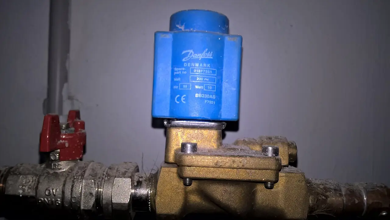
A proportional valve is an electrically commanded valve whose internal spool, poppet, or orifice setting varies continuously with the magnitude of its input signal, instead of snapping between two end positions. In the dominant hydraulic form, a proportional solenoid shifts a directional spool to any intermediate stroke, so the metering area opens in proportion to command current and the flow to a hydraulic cylinder or motor follows that command. The same principle drives proportional pressure and flow controls. The valve is the middle rung of the control ladder: it offers infinitely variable positioning like a servo, at response speeds and dirt tolerance far closer to a plain solenoid valve than to a servo valve.
Procurement engineers meet proportional valves on hydraulic presses, machine tools, injection molding machines, test stands, mobile equipment, and turbine auxiliary skids, and in pneumatic form on positioning and handling systems. The decisions that land on the buyer are quantitative: which NG subplate size per ISO 4401 and its rated flow at a stated pressure drop per metering notch, direct or pilot operated, with or without onboard electronics, with or without spool position feedback, and what oil cleanliness class the plant can actually hold. This page settles those decisions with numbers, because a proportional valve bought on flow size alone is the most commonly misapplied component in hydraulic packages.
This page decodes the proportional valve as a purchasing object: how proportional solenoids and spool metering work, what NG sizes and rated flow at 70 bar per notch mean on a datasheet, how onboard electronics and LVDT feedback change hysteresis and repeatability, what oil cleanliness the design demands, and how to write an RFQ that returns quotable hardware. It is written for engineers who specify motion and pressure control, not for readers who want a marketing summary.
Chapter 1 / 06
What a Proportional Valve Is and What Is Being Decided
The distinction that defines the family is positional. A conventional solenoid valve is a two-state device: coil energized, the element travels to one end; coil de-energized, a spring returns it. Between those states it has no stable stopping place, and control is limited to switching times measured in tens of milliseconds. A proportional valve replaces the switching solenoid with a proportional solenoid whose force rises with current over its working stroke, opposes it with springs and flow forces, and holds the spool at any intermediate position the current commands. The buyer is purchasing variable orifice area, and through it, variable flow or pressure, under electrical control.
Positioning the family on the control ladder is the first specification act. Below it, on/off solenoid valves deliver coarse sequencing at low cost and modest cleanliness needs. Above it, servo valves offer bandwidth below 10 ms and resolution an order of magnitude finer, at price, filtration, and commissioning cost to match. The proportional valve occupies the engineering middle: step responses of roughly 10 to 100 ms depending on size and pilot arrangement, hysteresis from about 5 percent for simple open-loop valves down to below 1 percent with onboard electronics and spool feedback, and oil cleanliness requirements strict enough to matter but survivable in a well-run plant. Most industrial motion and pressure duties live exactly in that band, which is why the product line is large and the catalogs confusing.
What an RFQ for this product actually settles is a short list of architecture decisions. First, size: the NG designation with its ISO 4401 subplate face, and the rated flow at the datum pressure drop per notch, 70 bar in most catalogs. Second, stage: direct operated for NG06 and NG10 flows, pilot operated from about NG16 upward where solenoids alone cannot shift the spool against flow forces. Third, electronics: onboard electronics integrated in the valve housing, or a separate amplifier card in the control cabinet. Fourth, feedback: none, or an LVDT spool position transducer closing the position loop inside the valve. Fifth, signal: voltage, current, or fieldbus. Each decision changes price by factors, and chapters 4 and 5 attach numbers to all of them.
The boundary against the electric alternative belongs in the same meeting. A hydraulic cylinder positioned by a proportional valve competes, on many machines, with a servo motor and servo drive turning a ball screw: the electric axis wins on efficiency and cleanliness, the hydraulic axis wins on force density and overload tolerance. The valve does not decide that contest alone; the power unit does. What the valve RFQ must state is the load case, the required velocity and force ranges, and the acceptable positioning error, so the supplier can confirm the architecture rather than just ship the size asked for. The same discipline applies at the low end, where a needle valve set by hand once per product changeover is the honest competitor to an open-loop proportional flow control.
Finally, the proportional valve is a control element, not a safety element. It does not hold load on its own when power fails; load holding needs a check valve or a pilot-operated holding valve sized for the load, and overpressure protection needs a relief function independent of the valve electronics. Packages that skip those mechanical backstops because the control is closed loop are the packages that bend cylinders. The RFQ should list load holding and relief as separate line items, and chapter 5 supplies the wording.
Chapter 2 / 06
How Proportional Spool Control Works
The proportional solenoid is the engine of the design. Inside it, coil current produces a magnetic force on an armature, and the geometry is shaped so that force is nearly flat over the working stroke and nearly proportional to current: more current, more force, at any position. That force pushes the spool against a return spring and against steady-state flow forces, and the spool settles where the forces balance. Because the spring is stiff and linear, spool position maps onto current with usefully small error. The metering edges of the spool then uncover flow area in the lap regions, and the notches ground into those edges set the shape of the flow versus command curve, the inherent characteristic an applications engineer reads before tuning anything.
Flow through the metering notch follows the orifice law: flow equals a discharge coefficient times uncovered area times the square root of two times the pressure drop divided by fluid density. Two consequences follow, and both drive datasheet practice. First, flow depends on pressure drop as much as on command, so a valve passing 120 L/min at the catalog datum of 70 bar per notch passes far less at a gentle 10 bar drop; sizing must use the drop the circuit actually presents. Second, the load steals pressure: as the hydraulic cylinder meets resistance, the pressure difference across the valve notch shrinks and flow falls at unchanged command. This load interference is why open-loop proportional control sets speed only approximately, and why the catalog datum of rated flow at 70 bar per notch exists, so that valves can be compared on one common number.
Hysteresis is the accuracy axis buyers care about most. As command rises and then falls, the same current produces two different spool positions, because magnetic hysteresis in the solenoid and mechanical friction on the spool act in opposite directions on each leg. Open-loop proportional valves show 3 to 5 percent of rated command between the two legs. Two countermeasures close most of the gap. Dither is a small ripple current superimposed on the command, commonly in the tens of milliampere at a frequency below the valve bandwidth, which keeps the spool micro-moving so friction never fully grips. Closed-loop position control adds an LVDT, a linear variable differential transformer, that measures true spool stroke; onboard electronics then correct the solenoid current until measured position matches command, cutting hysteresis from roughly 5 percent to below 1 percent and tightening repeatability to fractions of a percent.
Null behavior is the fourth concept. Most industrial spools are overlapped, with a small land covering the port at electrical zero, which gives leak-tight neutral and a deadband of input, often 10 to 20 percent of command span, during which the spool moves but no flow passes. The amplifier compensates by jumping the command across the deadband, and this deadband compensation is a tuning parameter, not a fixed constant: set it low and the axis is sluggish around zero, set it high and the cylinder creeps at null. Zero-lap spools traded for sensitivity leak at null and suit closed-loop servo work. Spool symbols on the datasheet, open center, closed center, tandem, read directly as circuit behavior, and chapter 3 tells the buyer which symbol belongs in which machine.
Response times close the dynamic picture. A direct operated NG06 valve steps fully open in roughly 10 to 25 ms; an NG10 in perhaps 30 to 60 ms; a pilot operated NG16 or NG25 needs 60 to 120 ms because the main stage volumes are larger. Onboard ramp generators stretch those numbers deliberately, limiting acceleration of the load. The servo valve crossing point is clear: below 10 ms of step response with sub-percent hysteresis is servo territory, and paying proportional prices while demanding servo dynamics is the classic mis-specification. Conversely, demanding only sequencing without variable speed is solenoid territory, and the proportional premium is wasted there. The datasheet line that matters is the step response measured from 0 to 100 percent command at rated pressure and rated flow, with the test conditions stated.
Chapter 3 / 06
Types, Mounting Sizes, and Duty Boundaries
Directional proportional valves, the volume product, mount on subplates standardized by ISO 4401, with sizes usually written both in CETOP designations and NG nominal sizes. NG06, CETOP 03, is the small workhorse of machine tools and handling; NG10, CETOP 05, covers general industrial motion; NG16, NG25, and NG32 serve presses and large actuators. Rated flows at the 70 bar per notch datum climb from roughly 30 L/min at NG06, through about 120 L/min at NG10, to 300, 700, and beyond 1,000 L/min at the largest faces. Subplate mounting is the point of the standard: the valve unbolts from the manifold without breaking pipe joints, and the manifold carries the complex internal drilling instead of hose bundles.
Stage architecture splits at about NG10. Direct operated valves shift the main spool with the solenoid alone, fine through NG10 and into small NG16. Pilot operated valves use a small direct valve as the first stage to route pilot pressure onto the ends of the main spool, which is how large flows are controlled by small coils; they add a pilot supply, internal from the P port or external, a pilot drain line, and roughly doubles the response time. The datasheet must state which arrangement a given frame uses, because the failure behavior differs: a direct valve centers under its springs on power loss, while a pilot valve's behavior depends on the pilot circuit configuration.
Beside directional valves, the family includes proportional pressure controls and proportional flow controls. A proportional relief valve sets system pressure electrically, which lets a press idle at low pressure and stroke at high pressure without manual needle settings; a proportional reducing valve commands branch pressure lower than supply, common on clamp circuits that must grip gently and hold hard. Proportional flow controls pair a proportional orifice with a pressure compensator so that flow follows command regardless of load, the electric descendant of the manual needle valve and pressure-compensated flow control. Knowing which of the three functions the machine actually needs is often worth more than any catalog parameter, because packages quote all three and buyers routinely order the wrong one.
Electronics divides the family in two again. Valves with onboard electronics, OBE in catalogs, integrate the amplifier, current regulator, dither generator, ramp generators, and on feedback valves the LVDT conditioning, inside the connector housing; the machine supplies 24 VDC and a 0 to 10 V or 4 to 20 mA command from a PLC analog output. Valves without OBE need a separate amplifier card in the cabinet, with the cost, wiring, and tuning access that implies, and some plants standardize on that deliberately for maintainability. Pneumatic proportional valves mirror the hydraulic structure at lower precision: positioning a pneumatic cylinder to a target needs paired valves plus feedback from a linear or rod-style transducer, and IO-Link parameterization has become the common electrical interface at that end of the market.
Duty boundaries are strict and mostly fluid-borne. Hydraulic proportional valves expect mineral oil in a viscosity band near 20 to 100 cSt and a temperature band roughly from minus 20 to 80 deg C, with 40 to 60 deg C the efficient center; water-based fluids, high water content, and exotic synthetics need explicit supplier confirmation. Cleanliness is the dominant boundary: proportional valves hold ISO 4406 cleanliness codes around 18/16/13, and silt in the 1 to 5 micron range, harmless to a gear pump, silently bonds spools. Cavitation and choked return flow damage metering notches, so return line pressure must stay within catalog limits. And the duty cycle of the coil matters on high-cycle machines: coil heating is steady state, and an enclosure rated for the panel environment costs little at order time and much at replacement time.
The table below consolidates the boundaries into a map a specifier can scan before the RFQ; each row pairs an application with the architecture that serves it and the shortcut that causes commissioning pain.
Application
Architecture that serves it
Shortcut to avoid
Machine tool axis, under 30 L/min
NG06 direct operated, OBE with LVDT
Open-loop valve on a positioning duty
Press speed and parallax control
NG16 or NG25 pilot operated, feedback, ramp generators
Pneumatic proportional pair, IO-Link interface, position feedback
Hydraulic-grade accuracy expected from air
Sequence-only switching duty
Plain solenoid valve
Proportional premium paid for two positions
High bandwidth, sub-percent accuracy
Servo valve with high cleanliness class
Proportional valve promised servo dynamics
Chapter 4 / 06
Key Specification Parameters
The table below decodes the datasheet lines that decide whether a quoted proportional valve matches the machine. Each row is purchase-defining; the paragraphs after the table explain what a complete answer must state.
Attribute
Typical range or options
What it decides
Size designation
NG06, NG10, NG16, NG25, NG32
Subplate per ISO 4401, manifold footprint, and rated flow class
Rated flow
about 30, 120, 300, 700, 1,000+ L/min at 70 bar per notch
Flow at the datum drop; actual circuit flow follows the orifice law
Maximum pressure
315 bar typical, 350 bar in frames
Pressure boundary per port, including the T port return limit
Stage
Direct operated NG06 to NG10; pilot operated NG16 up
Response time, pilot supply arrangement, and failure behavior
Hysteresis
3 to 5% open loop; below 1% with LVDT and OBE
Position accuracy without feedback correction
Repeatability
0.5 to 2% of command, better with feedback
Part-to-part consistency in speed or pressure loops
Step response
10 to 25 ms NG06; 30 to 60 ms NG10; 60 to 120 ms pilot stages
Loop bandwidth ceiling and the machine's cycle time floor
Input signal
0 to 10 V, 4 to 20 mA, PWM, fieldbus via OBE variants
PLC output card selection and cable practice
Supply and power
24 VDC, coil currents to about 3 A on pilot frames
Filtration class, commissioning procedure, and warranty terms
Rated flow is the row most often misread. The number is measured at 70 bar of drop per metering notch, a deliberately severe datum chosen so that a valve sized honestly at the datum has margin in a real circuit. If the circuit can only present 20 bar of drop across the valve at maximum load speed, the same NG10 valve passes roughly the square root of 20 over 70, about 53 percent, of its rated 120 L/min, and the axis runs slow. Sizing practice in chapter 5 handles this by rule: allocate about one third of supply pressure to the valve at maximum load flow, then verify the rated flow datum supports the resulting drop.
Hysteresis and repeatability rows must be read with their definitions. Hysteresis is the command difference between the rising and falling leg at the same output, stated as percent of rated command, measured without feedback action in open-loop valves and corrected by the LVDT loop in feedback valves. Repeatability is the spread of output at the same command approached from the same direction. A datasheet that quotes one number for both, or omits the test pressure and flow, is quoting marketing, and the RFQ should ask for the test conditions in writing. The step response row likewise needs its measurement definition: full 0 to 100 percent stroke at rated pressure, with smaller signal steps responding proportionally faster.
Spool configuration and leakage belong in the same paragraph because they trade against each other. Overlapped closed-center spools hold load drift to near zero at null and leak little, but carry the deadband already described; zero-lap spools give proportional response through null, leak continuously across the lap, and belong with feedback electronics. Datasheets state null leakage in L/min at rated pressure by spool symbol; on a heat-limited machine that number belongs in the energy balance. The check valve options on many subplates, crossport reliefs and anticavitation checks between the valve and the hydraulic cylinder, are order-code items that convert a bare valve into a protected one.
The comparison table below positions the three control hardware tiers against each other on the attributes that drive cost. It is the table to bring to the meeting where someone proposes a servo valve for a duty that a proportional valve serves, or vice versa.
Attribute
On/off solenoid valve
Proportional valve
Servo valve
Positions
Two, end to end
Infinite within stroke
Infinite within stroke
Hysteresis
Not applicable
3 to 5% open loop, below 1% with feedback
well below 1%
Step response
10 to 60 ms switching
10 to 100 ms by size
below 10 ms
Cleanliness need
Tolerant, 20/18/15 acceptable
18/16/13 or cleaner
cleanest classes, one to two codes finer
Flow and pressure range
Full catalog range
NG06 to NG32, to 315 bar
Mostly smaller frames
Relative cost, planning figure
1x
3 to 10x
10 to 30x
Chapter 5 / 06
Selection Decision Factors and RFQ Language
The decision sequence runs from the load backward to the valve, and each step produces a number the RFQ carries.
Fix the duty from the load: velocity and force ranges of the hydraulic cylinder or motor, cycle rate, and acceptable error in speed or position. Positioning tighter than about 0.5 mm or 1 percent of stroke usually pushes toward feedback electronics.
Compute maximum load flow, cylinder area times maximum speed, and add the intensification case for differential circuits before any valve size is chosen.
Apply the sizing rule: allocate about one third of supply pressure as valve drop at maximum load flow, then pick the NG size whose rated flow at 70 bar per notch comfortably covers the computed flow at the resulting drop.
Choose the stage: direct operated through NG10, pilot operated above; state pilot supply source and drain as order items.
Choose electronics and feedback: OBE versus cabinet amplifier, LVDT when hysteresis below about 1 percent or repeatability tighter than about 1 percent is required.
Fix the fluid targets: cleanliness 18/16/13 or cleaner, viscosity and temperature bands, and the filtration hardware that holds them, pressure filter at the valve supply and return line filtration sized for pump wear.
State the electrical environment: PLC analog card type, command signal, cable lengths, and any VFD or soft starter equipment sharing the cabinet, so the supplier can advise shielding practice.
List the mechanical protection: crossport relief, anticavitation check valve, and load holding function, each as separate order items rather than assumptions.
The sizing rule deserves one worked example, because it is the step buyers skip. Supply at 210 bar, cylinder needing 140 bar to overcome the load at full speed, leaving 70 bar of system drop to divide between valve and piping; assigning the valve a 35 bar share, one third of supply is 70, but practical circuits land nearer one sixth to one third, and the datum here is 35. If the computed flow at that drop is 60 L/min, an NG10 rated 120 L/min at 70 bar per notch covers it with margin, because 60 L/min at 35 bar needs the same metering area as about 85 L/min at 70 bar, comfortably inside the NG10 rating. The same arithmetic one size down shows NG06 failing at maximum speed, which is the mis-selection that arrives as a slow axis at commissioning.
Loop architecture decisions follow the valve choice. Open-loop velocity control from a PLC analog output suits conveyors and transfer lines where the load varies little; a single velocity feedback, or even a proximity sensor confirming end positions, keeps the logic honest. Closed-loop position control adds a transducer on the hydraulic cylinder, a rod-style magnetostrictive sensor in common practice, and the PID loop in the PLC or motion controller, tuned with the valve's documented bandwidth as the ceiling. The HMI panel carries the setpoints and the tuning screens, and the commissioning record should store the final gains. When the accuracy spec tightens beyond what a hydraulic axis holds, the migration is usually electric: the same budget moves to a servo motor and servo drive on a ball screw, and the hydraulic power unit retires with the valve. Pneumatic proportional systems follow the same shape with a pneumatic cylinder, paired valves, and a linear transducer, with IO-Link carrying parameterization where the valve generation supports it.
Filtration and commissioning are selection items, not installation details, because they decide whether the accuracy purchased survives the first year. Target ISO 4406 code 18/16/13 for proportional valves, one to two codes cleaner for servo valves, held by a pressure filter directly upstream of the valve with a beta-rated element and a clogging indicator wired to the PLC. Flush the loop with a dummy plate or bypass before the proportional valve is bolted on, replace the commissioning filter element after the first 50 to 100 hours, and sample the oil quarterly. Suppliers ask for oil analysis records before honoring contamination-related warranty claims, which tells the buyer exactly how most proportional valve failures actually happen.
The RFQ block should be written once and reused. A complete block reads: quantity; NG size and subplate standard; rated flow and its datum; maximum pressure by port; spool symbol and null overlap; stage and pilot arrangement; OBE or external amplifier; feedback, LVDT or none, with hysteresis and repeatability limits; command signal and supply; fault and enable contacts, landed through an industrial relay where the panel requires galvanic separation; cleanliness and viscosity targets; order-code options for crossport relief, anticavitation check valve, and load holding; required documentation, step response test, flow versus command curve, leakage at null, and the manifold drilling drawing. A quotation returned without the flow versus command curve or the hysteresis test condition is incomplete regardless of price, and on this product family that single sentence separates professional quotations from catalogs with part numbers.
Chapter 6 / 06
Installation, Standards, Failure Modes, and Maintenance
Installation is dominated by cleanliness in the first hours. Mount the valve on its subplate with the face scrupulously clean, the O-rings seated and lubricated with system oil, and the bolts torqued to the manifold drawing, because a distorted subplate face leaks externally at pressure. Fill the valve with clean oil before first command, and never commission a proportional valve into freshly piped circuits: flush through a bypass or dummy plate until oil sampling reaches the target code, then install the valve, run the first 50 to 100 hours, and replace the commissioning filter element. Electrical installation follows signal practice: shielded command cables, shields landed at one end, analog lines separated from the VFD and soft starter power wiring, and 24 VDC supplies sized for the coil inrush, with an industrial relay reserved for switching logic rather than for carrying proportional coil current.
Commissioning the loop has an order to it. With the pump off, verify the null: command zero and confirm the load holds still, adjusting deadband compensation until the cylinder neither creeps nor hesitates. Then stroke the axis at low speed and record the flow versus command behavior the machine actually shows, archiving the curve with the HMI panel commissioning screens, because it becomes the baseline for every future health check. Tune the loop from the bottom up, proportional gain first, integral action only as needed, ramp generators set last to shape acceleration. The position feedback devices deserve the same discipline as the valve: verify transducer scaling, and where discrete confirmation is needed, a proximity sensor at each end of travel catches mechanical drift that a healthy loop hides.
The standards frame is compact and useful. ISO 4401 defines the subplate mounting faces that make valves interchangeable between makers; the older CETOP designations map onto the same faces, NG06 to CETOP 03, NG10 to CETOP 05, and upward. ISO 4406 defines the cleanliness codes cited throughout this page, and ISO 10770 the test methods for electrically modulated hydraulic control valves, the reference behind honest step response and hysteresis figures. Circuit symbols follow ISO 1219. None of these documents chooses the valve; they make the datasheet comparable, which is why the RFQ should cite them when asking for test evidence.
Failure modes in service follow one dominant cause and a short tail. Contamination leads: hard particles score spools and silently abrade metering notches, while soft silt in the micron range electrochemically bonds spool lands, the silt lock condition where the valve ignores small commands and lurches across the deadband. Varnish from oxidized oil does the same and is the reason oil analysis trends matter on machines that run hot. Coil failure comes from heat and overvoltage: a coil enclosure full of chips runs hot, and hot coils open. Electronics faults show as drift or a frozen null, and the LVDT failure mode is worth remembering because it is diagnosed by swapping to the spare valve while the amplifier stays in place. Erosion of notches by cavitation from choked returns rounds the characteristic curve, which the baseline flow check catches years before the operator feels it.
Maintenance practice scales from the quarterly sample to the decade overhaul. Sample oil quarterly and act on the trend, not the absolute code; change filter elements on indicator, not calendar, and wire the indicators so the PLC logs them. Keep one spare valve or spare cartridge for critical axes, stored clean and filled, and store the commissioning records, baseline curves, loop gains, and deadband settings, with the machine file, because a replacement valve without those numbers needs a full recommissioning. Annually, repeat the flow versus command check against baseline and verify null holding with the pump at pressure. Every one of these checks costs less than one scrapped part from an axis that drifted, which on a press or a molding machine is the arithmetic that justifies the whole maintenance program.
FAQ
What is the difference between a proportional valve and a regular solenoid valve?
A regular solenoid valve has two stable positions, energized and de-energized, and controls only sequencing. A proportional valve holds its spool at any intermediate position in proportion to input current, so it controls flow magnitude, speed, or pressure continuously. Hysteresis, repeatability, and step response become specification items, and the oil cleanliness requirement rises accordingly. If a machine only needs switching, the simpler solenoid valve remains the correct and cheaper purchase.
What NG size do I need for my flow requirement?
Size from the circuit, not the pipe. Compute maximum load flow, then pick the NG size whose rated flow at 70 bar per notch covers that flow at the drop your circuit actually presents, following the common rule of giving the valve about one third of supply pressure at full load speed. As planning figures, NG06 rates near 30 L/min, NG10 near 120, NG16 near 300, and NG25 near 700 at the datum drop. One size up costs money; one size down costs the commissioning schedule.
What oil cleanliness does a proportional valve require?
Plan for ISO 4406 code 18/16/13 or cleaner, held by a beta-rated pressure filter upstream of the valve plus return line filtration. Servo valves ask for one to two codes cleaner. The practical failure mode is silt in the 1 to 5 micron range bonding the spool, which no strainer catches; it requires fine filtration and disciplined flushing at commissioning. Suppliers routinely request oil analysis records before accepting contamination-related warranty claims, which reflects how most failures occur.
What is hysteresis in a proportional valve and how is it reduced?
Hysteresis is the command difference between rising and falling signals at the same output, caused by magnetic hysteresis and spool friction; open-loop valves show roughly 3 to 5 percent of rated command. Dither, a small ripple current that keeps the spool micro-moving, reduces it. Closing the loop with an LVDT spool position sensor and onboard electronics cuts it from about 5 percent to below 1 percent and improves repeatability. Datasheets should state the test pressure and flow behind any hysteresis figure.
Do I need an LVDT feedback valve or is open loop enough?
Open loop suits duties where the load varies little and approximate speed control is acceptable, transfer lines and simple feeds, ideally with independent feedback for verification. Choose LVDT feedback when the specification demands hysteresis below about 1 percent, tight repeatability, or stable closed-loop position control of a hydraulic cylinder. The feedback valve prices the axis into motion control territory, so verify the simpler option cannot meet the requirement before paying for the finer one.
Can a proportional valve be used for pressure control?
Yes, through the dedicated pressure members of the family. A proportional relief valve sets system pressure electrically; a proportional reducing valve commands branch pressure below supply, common for clamp circuits. A directional valve throttling flow can influence pressure indirectly, but that is flow control, not pressure control, and it is a misapplication when the specification calls for regulated pressure. In closed loops, pair the pressure valve with a pressure transmitter or pressure sensor feeding the PLC for true regulation.
Why did my proportional valve stick after commissioning?
The dominant cause is contamination: silt-sized particles bond the spool lands, a condition called silt lock, and fresh pipework delivers that silt unless the loop was flushed with a bypass before the valve was installed. Symptoms are a valve that ignores small commands and lurches across its deadband. Remedies are a full oil flush, element replacement after the first 50 to 100 hours, finer pressure filtration at the valve, and an oil sample to confirm the cleanliness code. Do not fix it by turning up the command.