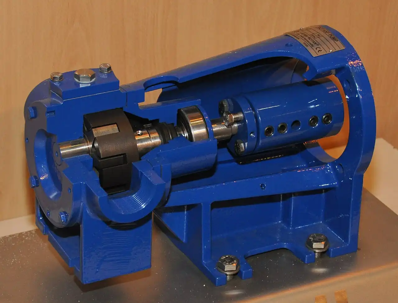
A lobe pump is a rotary positive displacement pump in which two or three meshing rotors, driven by external timing gears so they never touch each other, sweep pockets of liquid from the suction side to the discharge side along the pump casing. Because the rotors do not contact and the pumping chambers are open, the design passes solids, resists shear damage to the product, strips itself clean in place, and disassembles for inspection in minutes. Those four properties, more than any pressure or efficiency figure, are why lobe pumps own food, beverage, pharmaceutical, cosmetics, and viscous chemical transfer duty across thousands of plants.
The engineer who specifies a lobe pump is deciding a package, not a rotor set: rotor geometry and material against the product's shear sensitivity and solids; seal type against the cleaning and containment regime; the sanitary certification stack, 3-A, EHEDG, FDA compliance, ASME BPE surface finish, against the market the plant sells into; and the drive train, because a positive displacement pump's flow follows speed and its pressure follows the system, so the variable frequency drive or gearbox ratio is part of the pump specification. This page carries the numbers and standards that make those four decisions defensible.
This page treats the rotary lobe pump as a specification object: how noncontacting rotors displace product and where slip limits the head, which rotor geometries and materials suit shear sensitive and particulate products, which seal architectures survive CIP and SIP regimes, what the hygienic standards demand in surfaces and crevices, and what an RFQ must state about flow, viscosity, duty, and certification so the pump that arrives strips, cleans, and runs as promised.
Chapter 1 / 06
What a Lobe Pump Is and What Is Being Decided
Inside a lobe pump, two shafts carry rotors that mesh like gears but are driven through a separate timing gear set at the rear of the pump, so a engineered clearance of a few tenths of a millimeter is maintained between rotor lobes and between lobes and casing at all speeds. As the rotors turn, pockets form at the suction port, carry product around the casing periphery, and open to the discharge port where the meshing action expels them. There is no valving, no reciprocating mass, and no contact wear surface in the pumping chamber. Flow is a function of displacement per revolution times speed, and pressure is whatever the downstream system imposes up to the mechanical and slip limits of the pump.
What is being decided at purchase divides into four commitments. The first is the product compatibility commitment: rotor geometry, clearances, and materials chosen against viscosity range, shear sensitivity, solids size and hardness, and temperature. A biwing rotor passing fruit filling and a tri-lobe rotor dosing syrup are different machines in the same casing family. The second is the hygienic commitment: surface finishes, seal design, and certification, because a pump that cannot strip and clean in place in the plant's regime becomes the plant's contamination history. The third is the seal commitment: single, double with flush, or packed with throat bushing, chosen against the cleaning chemicals, the product hazard, and the run dry risk. The fourth is the drive commitment: speed range and control, because positive displacement flow follows rpm, and the most common lobe pump complaint, pulsation or flow mismatch, traces to a drive specification, not to the pump.
Within the pumping landscape the lobe pump's neighbors divide the duties. The gear pump carries similar viscosity range with higher pressure but internal metal contact that cannot pass solids and cannot clean in place; its domain is oil, polymer, and fuel. The progressive cavity pump handles higher solids loading and higher viscosity with gentler action but a stator elastomer that limits chemical and temperature range and that SIP steam degrades. The diaphragm pump runs dry freely and passes solids but pulsates hard and is rarely certified to the same hygienic level. The centrifugal pump dominates thin clean liquids at high flow but loses the viscosity battle above roughly 100 to 200 cP where a positive displacement machine takes over. The lobe pump holds the middle: 1 to 500 m3/h class flows, viscosity from water thin past 1,000,000 cP with speed derating, discharge pressure to about 12 to 20 bar depending on size and viscosity, and the cleanability the sanitary markets require.
The purchase context also includes the industry mark the plant must satisfy. Dairy and food plants in North America specify 3-A sanitary standards; European processors specify EHEDG certification for cleanability test evidence; pharmaceutical plants build to ASME BPE with documented surface finish and weld criteria; all of them lean on FDA compliant elastomers and plastics from 21 CFR listings. A lobe pump RFQ that does not name the mark invites a pump that is functionally identical and commercially unacceptable. The certification line is cheap at order time and impossible to retrofit.
Finally, what is being decided is the maintenance economy. Lobe pumps are maintainable in place: front cover off, rotors out, seals accessible, timing untouched if the front cover design preserves gear timing. A pump specified with rebuild kits, documented clearances, and a spares profile keeps a line running for decades; the same pump ordered as a price exercise with no clearances recorded becomes a mystery at the first rebuild. The RFQ should demand the clearance table and torque values for the model offered, which is the difference between a ten minute conversation with the supplier and a two week one.
Chapter 2 / 06
How the Rotors Move Product and Where Slip Begins
The displacement arithmetic is straightforward and is the basis of every selection. A rotor set displaces a fixed volume per revolution, published as displacement per 100 revolutions or per revolution; flow follows speed almost linearly minus slip. Slip is the backflow through the rotor clearances driven by the differential pressure, and it falls as viscosity rises: at 1 cP water thin, slip can claim 15 to 30 percent of displacement flow at rated pressure; at 100 cP it shrinks to a few percent; at 1,000 cP and above the pump meters nearly exactly. This is why the same rotor set that needs a variable frequency drive to hold flow on water holds flow dead steady on molasses, and why datasheets ask for the viscosity at the pumping temperature, not the drum temperature.
Viscosity also demands speed derating on the suction side. High viscosity liquid cannot fill the pumping pockets quickly; run the pump fast and it starves, cavitates in the classic sense of vapor bubbles at the port, and hammers. Manufacturers publish maximum speed versus viscosity curves: a rotor set that runs 500 rpm on water may be limited to 100 to 200 rpm at 50,000 cP and 20 to 50 rpm near 500,000 cP. Suction line design shares the duty: short, large diameter, no elbows at the port, and a flooded or pressurized suction. The pressure loss feeding the pump on 100,000 cP syrup through a long small line can exceed the pump's suction capability at any speed, which is a piping decision masquerading as a pump complaint.
Pulsation in lobe pumps is modest by positive displacement standards but not zero. Two lobe rotors deliver four volume deliveries per rotor revolution with a ripple commonly 5 to 15 percent of mean flow; tri-lobe and biwing geometries ripple less and at higher frequency. Pulsation dampeners and flexible connectors absorb the rest where the process cares. The rotor mesh also traps a small carryover volume that returns to suction each cycle; on shear sensitive products the geometric choice of rotor minimizes this recirculation, which is one of the reasons a tri-lobe is specified for yeast and cell culture fluids while a single lobe wing handles chunky salsa.
Pressure capability comes from the casing and the shaft seal stack, not from the rotors. Working pressure to about 12 bar is standard across sanitary sizes, with heavy duty and industrial casings to 20 to 25 bar. Because the machine is positive displacement, the pump must never see a closed discharge: a blockage downstream converts motor power into pressure until something yields, and the protection is a relief valve, internal or external, plus an overpressure trip on the drive. Every competent RFQ states the relief strategy; the alternatives arrive as bent covers and spray.
Net positive suction head requirements are stated by the manufacturer as NPSHr curves versus speed and viscosity, typically fractions of a bar on thin liquids. The plant's available NPSHa must clear NPSHr with margin, 0.5 bar or more on hot or volatile products, because positive displacement cavitation is louder and more damaging than the centrifugal variety: the collapsing bubbles erode rotor faces and casing bores within weeks. On the discharge side, the same duty piping should keep velocity in the hygienic range, commonly 1 to 3 m per second for product, so that clean in place flushing works at the design velocity of 1.5 m per second or better.
Efficiency expectations belong in the drive sizing discussion. Volumetric efficiency runs from about 70 to 85 percent on thin liquids to above 95 percent on viscous ones; mechanical efficiency sits in the 30 to 60 percent band depending on viscosity and pressure, with the best numbers on thick products at moderate pressure. Motor sizing uses the viscosity and pressure worst case with the startup torque at cold product temperature, which for fats and waxes can be several times the running torque; the gearmotor or VFD package specified from the water duty curve will stall on the first cold Monday, an outcome this page exists to prevent.
Chapter 3 / 06
Types, Construction, and Duty Boundaries
Rotor geometries divide the family. Tri-lobe rotors, three lobes per rotor, deliver smooth low ripple flow at moderate solids, the default for dairy, beverage, and pharma. Biwing rotors, two wings with large radius roots, pass larger particles and strip more completely, the choice for fruit preparations, sauces, and soups. Single lobe or "one wing" rotors pass very large particulates, whole fruit pieces and nuts, at reduced pressure. Multi-lobe and helical rotor sets tune ripple and shear further for cell culture and high purity duty. Rotors are offered in stainless steel, solid or hollow, hard surfaced or rubber covered for gentle solids handling, and in FDA compliant plastics for low pressure and light duty.
Casing and drive architecture separate the sanitary grades. Front loaded sanitary pumps, the volume market, have a clamp front cover, external bearing brackets with the timing gears isolated from product, and mechanical seals in the product wetted path; they strip without special tools. Heavy duty process pumps carry heavier shafts and bearings for higher pressure and viscosity. Multistage lobe pumps stack rotor sets for higher pressure in viscous duty. Industrial lobe pumps, non-sanitary, serve polymers, resins, and chemicals with packed or mechanical seals and cast or stainless casings, sharing the architecture with the sanitary line but not its surface finish or certification.
Seal architecture is the reliability decision on the pump. Single mechanical seals with EPDM or PTFE elastomers handle routine duty where product leakage to drain is acceptable. Double mechanical seals with flush or barrier fluid serve abrasive, hazardous, and vacuum duty, and every SIP steam regime, because steam behind a dry single seal face destroys it within cycles. Packed glands survive abuse in industrial duty but cannot be certified for the hygienic marks. Elastomer choice follows the cleaning chemistry: EPDM covers most caustic CIP regimes, PTFE covers solvents and oxidizers at higher cost, FKM covers oils and fats but fails many caustics; the cleaning chemical list belongs in the RFQ beside the product list.
Surface finish and drainability define the sanitary grades. Product wetted surfaces are polished to Ra 0.8 um or better for food duty, Ra 0.5 to 0.4 um or electropolished for dairy and beverage, and Ra 0.4 um or better with electropolish for pharma per ASME BPE; drainability requires the casing to self drain at a stated angle with no product traps at the port pockets. Welds in wetted paths are continuous and ground; crevices at dowels and bolts are eliminated in certified designs. The certification stack: 3-A symbol authorization witnessed by third parties, EHEDG type test for cleanability, FDA 21 CFR material compliance for elastomers and plastics, and ASME BPE for the pharma envelope.
Duty boundaries are concrete. Above roughly 20 to 25 bar, lobe pumps leave the field to the gear pump or the progressive cavity pump depending on solids. Above roughly 500 m3/h, twin screw or centrifugal machines take over on size. Dry running is limited to seconds on most mechanical seal designs; a lobe pump is not a diaphragm pump and must not be specified for unprimed startup. Abrasive slurries with hard particles wear rotor clearances and slip rises; if the product is abrasive and hot, a different pump family serves better. Steam sterilization demands the seal and elastomer stack for it, stated at order. And vacuum suction duties above about 0.6 to 0.8 bar vacuum need double seals and degassed product consideration.
The construction map below pairs common products with the configuration that survives them and the configuration that returns as a complaint.
Product and duty
Suitable configuration
Configuration to avoid
Milk, thin dairy, CIP caustic
Tri-lobe stainless, Ra 0.5 um, single or double seal EPDM, 3-A
FKM elastomers in caustic CIP; packed glands anywhere sanitary
Fruit filling with particulates
Biwing or single lobe rotors, large ports, low speed gearmotor
Tri-lobe at high speed, particle shear and pocket starvation
Pharma fluids, SIP 121 deg C
Tri-lobe, Ra 0.4 um electropolished, double seal with barrier, ASME BPE
Single mechanical seal under steam sterilization
Syrup, glucose, 10,000 to 100,000 cP
Heavy duty casing, derated speed, jacketed front cover, pressurized suction
Water duty speed curves applied to viscous product, starvation
Chocolate and fats, cold start
Jacketed casing and rotors, high startup torque drive, warmup interlock
Non jacketed pump started cold, seal and timing damage
Soap, polymer, resins, non sanitary
Industrial lobe or gear pump family with packed or single seal
Sanitary specification paid for where no mark is required, or the reverse
Abrasive slurry with hard solids
Progressive cavity or peristaltic family instead
Any close clearance lobe rotor set, slip grows monthly
Chapter 4 / 06
Key Specification Parameters
The decode table lists the parameters that decide whether a quoted lobe pump matches the duty; the commentary states what each row must carry in writing.
Attribute
Typical range or options
What it decides
Flow and speed range
0.5 to 500 m3/h family; 20 to 500 rpm typical sanitary
Rotor size class and the drive ratio and control strategy
Displacement
1 to 10,000 liters per 100 revolutions
Flow per rpm and metering accuracy at viscosity
Discharge pressure
to 12 bar standard; 20 to 25 bar heavy duty
Casing class, shaft seal stack, and relief strategy
Viscosity range
1 cP to 1,000,000 cP with speed derating
Speed derating curve applied and suction design
Temperature range
about minus 20 to 150 deg C product; SIP 121 deg C cycles
Elastomer grade, clearance class, jacketing need
Rotor geometry
Tri-lobe, biwing, single lobe, multi-lobe, helical
Solids passage, shear, ripple, and strip behavior
Materials and finish
316L wetted, Ra 0.8 to 0.4 um, electropolish optional
Certification stack eligibility and cleanability
Shaft seal
Single, double with flush or barrier, packed
Cleaning regime survival, containment, dry run limits
Connections
Tri-clamp, DIN, IDF, ASME BPE; NPT industrial
Line integration and drainability
Drive
Fixed speed gearmotor or VFD package
Flow control, cold start torque, and protection logic
The displacement and viscosity rows carry the selection arithmetic. Quote flow at the pumping temperature viscosity with the manufacturer's speed, and demand the speed limit curve versus viscosity for the offered rotor set; a pump quoted at 300 rpm on 50,000 cP product without the derating evidence is a starvation risk. On thin products, ask for the slip at working pressure so the real flow at speed is known rather than assumed.
The seal row carries the maintenance economics. State the cleaning regime: CIP chemicals, concentration and temperature; SIP steam pressure and hold time; and any product hazard that requires containment. The quotation should answer with a named seal type and elastomer set, its flush or barrier plan, and its expected life in the stated regime. Seal faces running unflushed through hot caustic and steam are the single most common early failure on sanitary lobe pumps, and it is a specification failure, not a manufacturing one.
Certification rows are documentary: 3-A symbol number, EHEDG certificate reference, FDA 21 CFR compliance statements for every wetted nonmetallic part, ASME BPE part 7 surface class where pharma. The certificates travel with the pump; the RFQ asks for their references in the offer, not after shipment.
Budget planning ranges across the family; USD at quantity one, ex works, pump end only for the sanitary classes and complete gearmotor packages where noted.
Class
Duty example
Budget range USD
Small sanitary front loaded, DN40 ports
10 m3/h dairy transfer
8,000 to 18,000
Mid sanitary with double seal and VFD
40 m3/h beverage, SIP
22,000 to 45,000
Pharma BPE grade electropolished
20 m3/h pharma fluid
35,000 to 70,000
Heavy duty viscous, jacketed
60 m3/h syrup at 50,000 cP
30,000 to 60,000
Large sanitary, DN150 ports
150 m3/h transfer
45,000 to 90,000
Seal and rotor rebuild kit
per pump
1,500 to 6,000
Chapter 5 / 06
Selection Decision Factors and RFQ Language
The decision list compresses the page into the order that writes the RFQ.
Fix the product envelope: viscosity at pumping temperature, density, temperature range, solids size and hardness, shear sensitivity, and any hazard or containment class.
Fix the duty envelope: flow minimum and maximum, discharge pressure from the system calculation, suction condition flooded or not, and daily cycle count.
Choose rotor geometry from the product: tri-lobe default, biwing or single lobe for particulates, multi-lobe or helical for high purity low shear.
Apply the viscosity derating curve and size the drive: speed at duty viscosity, motor with cold start torque, VFD where flow control or product changes exist.
Choose the seal architecture from the cleaning regime: single for benign CIP, double with barrier for SIP, hazardous, or vacuum duty; elastomers against the chemical list.
State the certification stack for the market: 3-A, EHEDG, FDA 21 CFR, ASME BPE as applicable, with certificate references in the offer.
State the protection strategy: internal or external relief valve, overpressure trip, dry run protection, and the minimum flow or speed floor.
Demand the documentation set: performance curve at duty viscosity, speed limit curve, NPSHr, clearance and torque table, IOM with strip and rebuild procedure, and spares list with kit numbers.
The recurring selection comparison is lobe against the neighboring positive displacement families at the same duty, and the table below frames it fairly.
Attribute
Lobe pump
Gear pump
Progressive cavity pump
Solids passage
good, geometry dependent
none, internal contact
very good, stator limited
Pressure capability
to about 12 to 25 bar
to 25 bar and above
to 8 to 16 bar typical
Viscosity ceiling
1,000,000 cP derated
similar high
very high, gentle
CIP and SIP capability
excellent, certified designs
poor
limited by stator elastomer
Dry run tolerance
seconds on seals
brief on loaded seals
very low without liquid
Strip for inspection
minutes, front cover
workshop job
moderate, stator pull
Typical duty
food, pharma, viscous transfer
oils, polymers, fuels
sludge, slurry, thick paste
The RFQ block itself should read: quantity; product and duty envelope as above; rotor geometry and material; casing and finish class; seal plan with elastomers; connections and orientation; certification stack with references; drive package with control range and protections; relief and safety strategy; performance curve at duty viscosity and speed limit curve; and documentation and spares list. Suppliers answering with water curves against a syrup duty have not answered, and the buyer who catches it in the offer stage has saved the commissioning week.
Neighbors in the piping scheme deserve their lines too. A Y strainer or basket strainer upstream on new lines protects rotor clearances from weld bead during commissioning. Isolation valves, whether ball valve or butterfly valve pattern, must be full bore so the suction path is not throttled. A check valve prevents siphon backflow on tall discharges where the product can drain the line. For additive dosing at exact ratios, keep a metering pump on that duty and the lobe pump on transfer, because the lobe meters well against viscosity but the dedicated dosing instrument owns the accuracy class. And on CIP circuits, the pump specification should state the CIP flow velocity target, 1.5 m per second class, so the rotor speed chosen for cleaning matches the line's need rather than the product duty's habit.
Chapter 6 / 06
Installation, Standards, Failure Modes, and Maintenance
Installation practice protects the clearances and the seals. Mount the pump with its suction port fed from below or flooded, never from a rising trap that can starve it; keep suction lines short and one or two sizes up for viscous products. Align the coupling to the vendor tolerance, a few tenths of a millimeter, because timing gear and bearing life follow alignment. Orientation for drainability: sanitary installs slope the casing to drain at the stated angle with the front cover down or per the vendor drawing. Torque the front cover clamp bolts evenly to the table; uneven clamping distorts the casing bore and rotor clearances. Before first run, verify rotation, confirm the relief path is open, and start against an open discharge; the first minutes run at reduced speed on viscous product confirm priming and current draw.
The standards and certification stack is the contract's cleanability backbone. 3-A sanitary standards define the design criteria, materials, surfaces, and cleanability for the dairy and food marks, with third party symbol authorization. EHEDG guidelines and type test certification document cleanability in place for the European market. FDA 21 CFR listings govern elastomer and plastic contact materials. ASME BPE governs the bioprocessing envelope, surface classes, weld criteria, and drainability. On the mechanical side, the manufacturer's clearance tables and the hydraulic performance statements stand behind the selection; there is no ISO pump test code specific to lobe pumps, so the performance curve and its tolerance clause in the purchase documents are the reference the plant owns.
Failure modes in service follow a short list. Seal failure leads the list: dry running, hot caustic without flush, or steam behind single faces; remedy is the seal plan and interlocks specified in chapter 4, plus seal plan monitoring where the product is hazardous. Rotor and casing wear: abrasive particles or repeated starved running; remedy is strainer discipline, suction verification, and clearance measurement at rebuild; the slip test, flow at speed and pressure against the curve, catches wear without opening the pump. Timing gear damage: overload events, reverse rotation, or foreign metal; remedy is the relief and trip strategy and coupling guards. Bearing failure: misalignment and lubrication lapse; remedy is alignment records and the lubrication schedule. Product contamination events trace to dead legs and worn surface finish, not to the rotors; the annual strip inspection of surface condition and seal faces is the control, recorded against the certification file.
Maintenance intervals scale with regime. Daily in CIP plants: verify seal flush or barrier level, listen for starved running, check leakage weeps. Weekly: verify coupling and clamp torque marks. Quarterly or per production campaign: strip inspection, rotor clearance measurement against the table, seal face inspection, elastomer condition. Annually: full rebuild with kits, surface finish inspection, certification file review, and recalibration of the VFD and trip settings. On pharma duty, the maintenance record is part of the validation file; on food duty, it is part of the audit file; either way the kit numbers and clearance table demanded in the RFQ are what make the rebuild an hour of work instead of an archaeology project.
Spares economics are favorable when planned: a seal kit, one rotor set, gaskets, and bearings per pump class cover years of operation at a fraction of pump price. The plant that stores the kit with the IOM manual and the clearance table specific to the serial number gets mean time to repair measured in hours. That practice, more than any option on the order, is what makes the lobe pump the long service machine it is designed to be.
FAQ
What viscosity can a lobe pump handle, and how fast can it run?
Lobe pumps move product from water thin past 1,000,000 cP, but speed must derate with viscosity: a rotor set running 400 to 500 rpm on thin liquid may be limited to 100 to 200 rpm at 50,000 cP and 20 to 50 rpm near 500,000 cP. Manufacturers publish speed limit versus viscosity curves; selecting without them risks suction starvation and cavitation damage. Always quote viscosity at the pumping temperature.
Can a lobe pump run dry?
Only for seconds, and only briefly at low speed. The timing gears are oil lubricated, but the mechanical seals need product or flush liquid for cooling and lubrication; dry running scores the faces within tens of seconds. For duties with dry start risk, specify double seals with a barrier plan or dry run protection on the drive. If the process genuinely runs unprimed, a diaphragm pump is the correct family.
Which certifications do I actually need for food and pharma?
Name the mark your market audits against: 3-A symbol for US dairy and food, EHEDG certification for European cleanability evidence, FDA 21 CFR compliance for every wetted elastomer and plastic, and ASME BPE surface and weld classes for bioprocessing. Ask for certificate references in the offer. Buying a functionally identical pump without the required mark is a rejected lot waiting to happen.
Why does my lobe pump lose flow over months?
Progressive flow loss at fixed speed and pressure is usually wear related slip: abrasive particles or starved running have opened rotor and casing clearances. Measure clearances at strip and compare with the vendor table, or run a slip test by checking flow against the original curve. When slip grows beyond tolerance, rotor replacement or resizing restores performance; the clearance table demanded at purchase is what makes this a controlled decision.
Single or double mechanical seal: how do I choose?
Choose single seals for benign products with straightforward CIP, accepting flush where product dries on the faces. Choose double seals with flush or barrier whenever the duty includes steam sterilization, abrasive or hazardous product, vacuum suction, or containment requirements; steam behind an unflushed single face destroys it within cycles. Match elastomers to the cleaning chemicals: EPDM for caustic regimes, PTFE or FKM where solvents demand, noting FKM fails many caustics.
What discharge pressure can a lobe pump reach?
Standard sanitary designs reach about 12 bar with heavy duty and industrial casings extending to 20 to 25 bar; multistage lobe designs extend further in viscous duty. Because the pump is positive displacement, always pair the rating with a relief valve and overpressure trip; a closed discharge will convert motor power into pressure until something yields. State the system calculated pressure, not the pump's maximum, in the RFQ.
How do I size the drive for viscous products?
Size from the viscosity and pressure worst case, not the water curve: apply the speed derating curve, compute torque at duty conditions, then check cold start torque, which for fats, chocolate, and waxes can be several times running torque. A VFD with adequate overload rating plus a gearmotor ratio chosen for the duty speed range handles both. Drives sized on thin liquid data stall on the first cold start of the season.