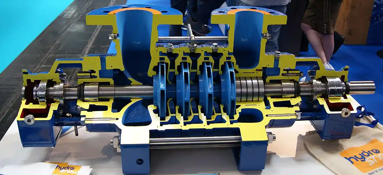
A steam drum is the upper pressure vessel of a water tube boiler or heat recovery steam generator where the steam water mixture returning from the generating tubes is separated into dry saturated steam for the process and water for continued circulation. The drum receives a two phase froth from risers, passes it through primary separators, cyclones or baffles that spin and impact most of the water out, and then through secondary dryers, chevron or mesh scrubber elements that polish the steam to a purity target, commonly measured in parts per billion of silica and sodium or in moisture carryover below a quarter to one percent. Feedwater enters through the drum from the boiler feed pump and economizer, distribution and chemical feed hardware arrange it gently, and the water level held between trip bands protects both the generating bank, which must not starve, and the superheater or turbine, which must not see water.
Procurement engineers meet steam drums as the heart of industrial water tube package boilers, field erected power boilers, and the multiple pressure level drums of heat recovery steam generators, and as replacement internals and retrofit level projects on the installed fleet. The decision this page settles is what a drum purchase or internals purchase actually specifies: the separation duty against the steaming rate, the internals architecture from cyclones to dryers, the level instrumentation and control philosophy against shrink and swell, the blowdown and chemical feed scope that keeps the water chemistry honest, and the ASME Section I design basis of the vessel itself. The answer lands as an RFQ line set, steaming rate and purity, internals, nozzles, and code basis, and every chapter below feeds that line set so the drum delivers dry steam at every load instead of becoming the plant's carryover story.
This page treats the steam drum as a purchasing object: how cyclones and dryers separate steam from water, how circulation and level behavior write the control story, what blowdown and chemistry hardware the drum carries, what Section I expects of the vessel, and how the whole decision folds into a defensible RFQ for new drums and internals retrofits alike. It is written for engineers who issue specifications on boiler equipment, not for readers who want a brochure summary.
Chapter 1 / 06
What a Steam Drum Is and What Is Being Decided
The defining act of the vessel is steam water separation under pressure, and everything in the drum exists to do it quietly. Water tube boiler circulation carries water from the drum down downcomers to headers and lower outlets, up through generating tubes where heat makes a steam water mixture, and back up risers into the drum. That mixture arrives as a high velocity froth that would blow straight through a simple gravity space at industrial steaming rates, so the drum hardware intercepts it in stages: primary separators remove the bulk water mechanically, secondary dryers polish the steam, and the disengaging surface and water inventory between them buffer transients. The drum is simultaneously a separator, a water reservoir feeding the boiler feed pump suction through the downcomer system, a chemistry vessel receiving feedwater and chemicals and letting blowdown leave, and the level measurement point the whole boiler protects.
What is being decided in this purchase depends on which purchase it is, and honesty about that is the first specification act. A new drum with the boiler is decided mostly by the boiler vendor's cycle and the buyer's scrutiny of internals and nozzles, and the meaningful buyer decisions are purity targets, level instrumentation scope, and code basis. A replacement drum on an existing boiler adds design replication duties, ASME Section I construction with the original design envelope or its updated code case, nozzle loads against existing piping, and transport and rigging scope. An internals retrofit, the most common standalone purchase, decides separation capacity against current steaming rates, carries the mechanical fit inside an existing shell, and lives or dies by the carryover test before and after. Each of those purchases has a different RFQ, and this page arms all three.
Against its neighbors the steam drum occupies precise ground in the boiler house. The economizer feeds the drum with hot feedwater and is the water side heat recovery partner with its own page. The deaerator removes oxygen upstream of the feed pump and drum. The boiler feed pump delivers feedwater to the drum, and the surface condenser receives what the steam becomes at the turbine, completing the cycle that this page sits atop. A flash tank makes steam from pressure drop, usually condensate, a different machine that this page's neighbors occasionally confuse it with, and the air receiver and expansion tank are utility vessels with no separation duty. Within today's boiler envelopes, the heat recovery steam generator carries its own drums or once through circuits, and its page handles that family, while the mud drum and single against two drum arrangements of field erected practice appear in this page's Types discussion as arrangements of the same steam drum duty.
Standards organize the datasheet. ASME Section I, the Power Boilers code, governs the drum as a boiler pressure part, its design, materials, welding, inspection, and hydrotest, with the stamp and documentation the jurisdiction expects, and the design basis includes the corrosion allowance and the nozzle reinforcement the piping loads imply. Performance vocabulary comes from ABMA and ASME practice, steam purity targets in parts per billion for sodium and silica on utility duty, moisture carryover fractions on industrial duty, and drum internal sizing practice from the boiler industry's engineering tradition. Water chemistry targets, from ASME consensus practice for boiler water in the operating ranges, write what the blowdown and chemical feed hardware must deliver. A datasheet that quotes a drum with no purity basis and no code line is a price tag, not a specification.
The station around the drum deserves naming in the RFQ too. Feed arrives from the boiler feed pump through the economizer, and the drum internals distribute it without disturbing the separation surface. Chemical feed, phosphate and treatment chemicals, enters by shot or line to mix below the water line, and continuous blowdown leaves from a surface skimmer or dedicated nozzle on its way to a flash tank and heat recovery, with intermittent bottom blow from the mud drum or headers completing the solids control story. Level measurement is the safety spine, a level transmitter and independent level switches or a redundant transmitter architecture feeding the burner management trip, with a magnetic level gauge for local truth. Safety valves on the drum, the safety relief valve family at boiler service, and steam offtake and downcomer nozzles sized and load rated for the piping analysis complete the vessel's connection to the plant.
Chapter 2 / 06
How Internals Separate Steam from Water
Primary separators do the bulk of the work, and the cyclone is the industrial standard. The riser mixture enters cyclone separators, vertical cylinders with tangential inlets and swirling vanes, and the spin throws water to the wall while steam rises through the center, the water draining through skirts below the water line so it does not re entrain. A battery of cyclones across the drum floor handles the total riser flow, and their capacity per unit sets the count, with each cyclone rated at a steam and water throughput that the vendor sizing should state against the steaming rate. Cheaper primary hardware, baffle and pan arrangements, appears on small and low rate duty, and the honest retrofit question is whether the old baffles were ever rated for the steaming rate the boiler now runs.
Secondary dryers polish what the cyclones miss. The steam leaving the primary section carries a mist of fine droplets, and chevron dryers, corrugated plate bundles that turn the flow a series of times so droplets impinge and drain, remove it by inertia, with mesh pads appearing as an alternative on lower pressure duty. The dryer bank sits above the water surface with drainage routed back below it, and its sizing follows the same velocity window logic as any mist eliminator, too slow and the mist passes, too fast and the water re entrains off the plates. The combination, cyclones then dryers, is what delivers the purity numbers: industrial boilers quote moisture carryover below roughly a quarter percent, utility practice quotes steam purity in parts per billion of sodium and silica, and the internals sizing basis for those numbers belongs in the purchase file.
Circulation is the physics the internals ride on. Natural circulation boilers rely on the density difference between water in downcomers and the mixture in risers to drive flow, and the drum is the head tank that makes the loop, with the water level in the drum setting the driving head available to the furnace circuits. The drum stores minutes of water inventory against transients, which is why load changes show in drum level before anywhere else, and why the control story, three element control of feedwater against steam flow and level, exists to feed the pump and valve reality. Assisted and controlled circulation designs add pumps to the downcomer system on larger units, and once through designs eliminate the drum entirely, which is the boundary this page's selection chapter marks honestly.
Water level behavior in the drum is the control and safety story buyers must specify against. Shrink and swell: when load rises, the expanding steam volumes in the generating tubes swell the mixture and the drum level rises before the feed has moved, and when load falls the level shrinks, so a naive level controller throttles feed in exactly the wrong direction on every transient. Three element control, level with steam flow and feedwater feedforward, handles it, and the instrumentation architecture, transmitter ranges, redundant devices, and the independent low level trip to burner management, is specification content with a safety function. Level bands, normal, high alarm, high high trip, low alarm, low low trip, are written from the internals and circulation behavior, and the RFQ should demand the basis, not just the numbers.
Chemistry and blowdown complete the drum's duties. The drum concentrates solids, feedwater impurities arrive and stay as steam leaves pure, so continuous blowdown removes a controlled stream from the water surface or dedicated zone, replaced by fresher feed, holding total dissolved solids at the target, with the blowdown heat recoverable through a flash tank and exchanger. Chemical treatment, phosphate programs and their alternatives, is fed to the drum water to condition the solids that remain, and the internal feed and chemical distribution pipes arrange both without disturbing separation. Silica behavior deserves special mention, its volatility rises with pressure and it carries into steam and deposits on turbine blades, which is why silica targets tighten with pressure and the silica analyzer joins the plant's chemistry bench on utility duty.
Chapter 3 / 06
Drum Arrangements, Internals Options, and Duty Boundaries
Drum arrangements in the field read in a few families. The package water tube boiler carries one steam drum over a generating bank, with or without a lower mud drum in two drum form, delivered as a factory unit with internals installed. Field erected power boilers follow the same single drum architecture at scale, with welded or bolted internals shipped as a fit out. The single drum with waterwalls and generating banks is the modern standard because it separates the steam water duty from the solids collection duty, the mud drum of two drum designs holding bottom blow and solids, an arrangement still built and retrofitted where its maintenance story fits. Heat recovery steam generators carry drums per pressure level, high, intermediate, and low pressure drums in multi level machines, smaller and differently internals than power boilers, and once through HRSG circuits carry no drum at all.
Internals options divide by duty and vendor architecture. The cyclone and dryer battery is the high capacity standard, sized per steaming rate, with variations in cyclone count, diameter, and inlet design that vendors engineer around. Baffle and scrubber box arrangements serve smaller package duty. Feedwater distribution comes as internal feed pipes with spray or perforated design, and chemical feed as quills or a chemical line to below the separation zone. Blowdown and skimmer internals arrange surface removal, and separators for steam offtake, dry pipes and perforated distributions, polish the steam path on designs that need it. The internals purchase also carries the hardware of installation, drums are pressure parts and internals are bolted and welded inside them, so hangers, seal plates, and manway access belong on the drawing set the RFQ demands.
Boundaries are worth stating bluntly. This page is the steam drum authority and does not double the whole boiler, the heat recovery steam generator page owns that family with its multi pressure drums, and once through boilers and their separators, which have no drum in the recirculating sense, are a boundary this page marks rather than covers. It is not a flash tank, which flashes condensate to lower pressure steam, not a steam separator in the line sense, which guards a header or machine downstream, and not the deaerator or feedwater heater, which condition water before the drum. The internals retrofit market deserves its own boundary: a carryover problem is diagnosed against steaming rate, water chemistry, and level behavior before any hardware is bought, because internals fix separation capacity, not chemistry carryover. The map below compresses the boundaries into one table.
The table below decodes the datasheet lines that decide whether a quoted drum or internals package matches the boiler and the steam the plant sells. Each row is a purchase defining parameter; the paragraphs after the table explain what to demand and what a weak answer looks like.
Attribute
Typical range or options
What it decides
Steaming rate
Design and maximum continuous
Cyclone count, dryer area, and every internals capacity line
Design pressure and temperature
Per Section I with corrosion allowance
Shell thickness, materials, stamp and documentation
Steam purity target
Carryover fraction or ppb sodium and silica
The acceptance basis for internals and chemistry together
Primary separator type and count
Cyclones rated per unit; baffles on small duty
Bulk separation capacity at maximum rate
Secondary dryer type and area
Chevron banks, mesh on low pressure duty
Polishing capacity and its velocity window
Drum dimensions
Inside diameter and length by boiler design
Steam release area, inventory, and shipping limits
Nozzle schedule and loads
Feed, steam, downcomer, blowdown, safety, level
Piping interface and local stresses at the shell
Level instrumentation scope
Transmitters, switches or redundancy, local gauge
Control and trip architecture against shrink swell
Blowdown and chemical feed
Continuous skimmer, chemical line, distribution
Chemistry control hardware inside the vessel
Code basis and documentation
ASME Section I stamp, data reports, internals drawings
Legal envelope and the file the inspection reads
The purity and internals rows carry the warranty. Demand the internals sizing basis, cyclone count and per unit rating at maximum steaming rate, dryer area and its velocity window, and the carryover or purity guarantee tied to a test method, isokinetic steam sampling for sodium and silica or the moisture carryover test, because a purity number without a method is a hope. On retrofits, demand the fit survey, internals assemblies against manway sizes and existing hangers, and the installation sequence inside a vessel people enter on a confined space permit. The quotation that quotes internals by weight is quoting steel, not separation.
The level and nozzle rows set the safety interface. Level instrumentation should be scoped as a safety function: redundant transmitters or transmitter plus independent switches feeding both control and the burner management low level trip, with ranges and setpoints written from the internals behavior, and the RFQ should demand the shrink swell basis for the bands. Nozzles carry the piping analysis loads, and replacement drums live or die by the nozzle schedule match, location, size, and load rating, to existing pipe, so the RFQ includes the loads or demands their analysis. The second table compresses the water side scope the way a specification meeting argues it.
Water side scope
Specify
Check before order
Feedwater distribution
Internal feed pipe with spray or perforations
Feed temperature and quench behavior at the shell
Continuous blowdown
Skimmer or surface nozzle with valve and flash tank path
Blowdown rate basis against TDS target
Chemical feed
Quill or line below separation zone
Treatment program compatibility with internals
Level measurement
Redundant transmitters plus independent trip device
Setpoint bands against internals and circulation
Safety valves
Drum mounted per Section I capacity rules
Set pressure and capacity coordination with superheater
Chemistry monitoring
Conductivity, silica analyzer on utility duty
Sample conditioning and ppb method fit
Chapter 5 / 06
Selection Decision Factors and RFQ Language
The decision sequence is short enough to run as a specification meeting checklist, and each step eliminates a class of quotations before price comparisons begin.
State the boiler duty honestly: steaming rate at design and maximum, operating pressure, and the steam the downstream expects, process steam tolerating moisture against turbine duty needing parts per billion.
Write the purity target as a number with a test method, and make the internals and the chemistry program jointly accountable for it in the acceptance basis.
Choose internals by sizing basis: cyclone count and rating at maximum rate, dryer area and velocity window, with the vendor calculation delivered, not asserted.
For vessels, fix the Section I envelope: design conditions, corrosion allowance, nozzle schedule with loads, and the stamp and documentation set.
Scope the level and safety architecture: redundant measurement feeding control and the independent low level trip, bands with their shrink swell basis, and safety relief valve coordination.
Scope the water side hardware: feed distribution, chemical feed, continuous blowdown with its flash tank and heat recovery path, and bottom blow interfaces.
For retrofits, demand the diagnosis first: chemistry and level behavior ruled out before internals are bought, and the carryover test before and after as the acceptance.
Fix the verification evidence: internals sizing calculation, purity test method, hydrotest and stamp documentation, and the drawings and manway access the installation needs.
Against neighboring equipment the comparison a specifier needs runs as follows, and it belongs here in the selection chapter rather than in the page title. The economizer heats the feed on its way to the drum, the deaerator removes the oxygen before the feed pump, and the boiler feed pump delivers through both, so the drum's water story is a chain with each link on its own page. The surface condenser and condensate return close the cycle. The flash tank handles blowdown and condensate flash on the discharge side of the drum's chemistry duty. The heat recovery steam generator page owns the multi pressure drum family of gas turbine plants, and once through designs mark the boundary where no drum exists. Name the neighbors and every vendor quotes the same machine against the same steam.
The RFQ block should be written once and reused. A complete block reads: steaming rate at design and maximum continuous with operating pressure and temperature; purity target with test method; drum or internals scope named; internals sizing basis with cyclone ratings and dryer window and the calculation deliverable; Section I design conditions with corrosion allowance and nozzle schedule with piping loads; level instrumentation architecture with redundant measurement and independent trip device, ranges, and band basis; safety relief valve scope with coordination basis; feed distribution, chemical feed, and continuous blowdown hardware with flash tank interface; materials with certificates; internals installation scope including manway access and hangers; and the acceptance basis, carryover or purity test before and after for retrofits, hydrotest and stamp for vessels. A quotation returned without the sizing calculation or the purity test method is incomplete at any price.
Chapter 6 / 06
Installation, Standards, Failure Modes, and Maintenance
Installation quality decides whether the internals ever performed as sized. New drums arrive with internals shipped installed or as fit out packages, and the fit out follows the assembly sequence inside a confined space with the hangers and seal plates actually sealing, because a cyclone skirt left short recirculates steam under the water and undoes the battery. Piping to the nozzles goes in per the load analysis, supports and spring hangers set before hydrotest, and safety valves installed with their drips and drains. Level transmitters and gauges mount with their water columns and equalizing lines proved, because the commissioning of level is the commissioning of the trip. Internal chemical and feed piping is flushed and proved for direction, a reversed feed pipe is a quiet separator killer.
Commissioning proves separation and level together. The carryover or purity test runs at maximum steaming rate with the agreed method, isokinetic steam sampling for chemistry or the moisture method, and it is the acceptance basis the RFQ wrote, before the boiler is signed off. Level behavior is proven by transient: load steps are thrown at the boiler on purpose and the three element control tuned against the measured shrink swell, and the trip bands are verified by calibration and functional test, low level trip to burner management proven end to end. The blowdown system is set to the chemistry program's rate and the flash tank and heat recovery path commissioned, with the conductivity and silica analyzers calibrated to the ranges the targets live in.
Failure modes in service follow a short and predictable list. Carryover is the headline failure and arrives from three doors: internals damage, cyclone skirts corroded or dryers displaced, chemistry upset, high dissolved solids or a treatment program foaming, and level misbehavior, high water or a swelling transient the control mishandled, and the diagnosis walks all three before buying anything. Internals corrosion and erosion, oxygen attack pitting thinning hangers and cyclone walls, chemical cleaning damage to dryer plates, and plain fatigue at attachment welds, show up on internal inspection at outages, which is why the manway and inspection scope belongs to the purchase. Level instrument drift and water column plugging move the indicated level away from the real one, and the calibration and proof calendar is the defense. Chemistry upsets concentrate solids and foam, raising carryover without any hardware fault, and the blowdown and analyzer trend is the early signal. Stamp and documentation failures are rare and expensive, found when a jurisdiction review meets an incomplete data report, which is why the code file ships with the drum and lives with the boiler records.
Maintenance intervals scale with pressure and duty severity. Industrial drums on treated feedwater get internal inspection at the boiler's major outage cadence, with cyclones and dryers inspected for security and thinning, hangers and seal plates renewed as found, and the level columns and transmitters serviced on the instrument calendar. Utility pressure drums tighten the chemistry bench, silica and sodium analyzers reading parts per billion, and shorten the water column and transmitter proof calendar because the trip they feed is turbine protection. Every outage produces numbers, thickness readings, carryover test results, chemistry trends, and those numbers calibrate the next internals purchase and the next chemistry program revision, which is how a purchasing file gets smarter instead of just older.
FAQ
What steam purity should a drum deliver?
Duty writes the number. Industrial process steam commonly accepts moisture carryover below roughly a quarter to one percent, while turbine duty and utility practice specify steam purity in parts per billion, sodium and silica each in the low tens or below by pressure class. Write the target with its test method, isokinetic steam sampling for chemistry or a moisture carryover test, because internals and the water chemistry program are jointly accountable and the acceptance basis needs the method.
How do cyclone separators and dryers divide the work?
Cyclones are the primary stage, spinning the riser mixture so bulk water leaves the steam by inertia, each unit rated for a steam and water throughput that sets the battery count. Chevron dryers are the secondary stage, turning the remaining mist through corrugated plates so droplets impinge and drain, sized to a velocity window like any mist eliminator. Together they deliver the purity number, and the sizing basis for both belongs in the delivered calculation, not in a catalog curve.
What are shrink and swell and why do they matter?
Load transients change the steam volume in the generating tubes, so on a load rise the drum level swells upward before feedwater moves and on a fall it shrinks, in both cases lying to a naive level controller that then moves feed the wrong way. Three element control, level corrected by steam flow and feedwater feedforward, handles it, and the level trip bands are written from that behavior, which is why the instrumentation architecture and its basis are specification content, not accessories.
When should I replace drum internals?
Replace when the sizing basis no longer covers the steaming rate, a boiler pushed past original capacity on old baffles is the classic case, or when inspection finds corrosion, erosion, or displacement that leaks steam past the separators. Diagnose carryover first against chemistry and level behavior, because internals fix separation capacity, not dissolved solids foaming, and the before and after carryover test is the acceptance for any retrofit.
What code governs a steam drum?
ASME Section I, the Power Boilers code, governs the drum as a boiler pressure part, design, materials, welding, inspection, hydrotest, and stamping, with data reports filed to the jurisdiction. Replacement drums built to the original design or its current code practice carry the same envelope, and the nozzle loads against existing piping are part of that design, not an afterthought for the pipefitters.
How is drum level instrumented for safety?
As a safety function: a level transmitter for control, redundant transmitters or an independent switch device for the trips, and the low level trip wired to burner management independently of the control loop. Local truth comes from a water column and gauge, and the calibration and proof test calendar is written to the trip's importance, because the whole boiler exists above that water line and the turbine exists below the steam it protects.
What water chemistry scope belongs to the drum purchase?
The hardware that delivers the program: internal feed distribution, chemical feed quills or lines below the separation zone, and continuous blowdown with its skimmer or surface nozzle, valve, and flash tank path, plus the monitoring the targets imply, conductivity always and silica and sodium analyzers on utility duty. The program itself belongs to the water treatment specialist, but the drum hardware that feeds, doses, and blows down is bought with the drum, and its sizing basis is RFQ content.