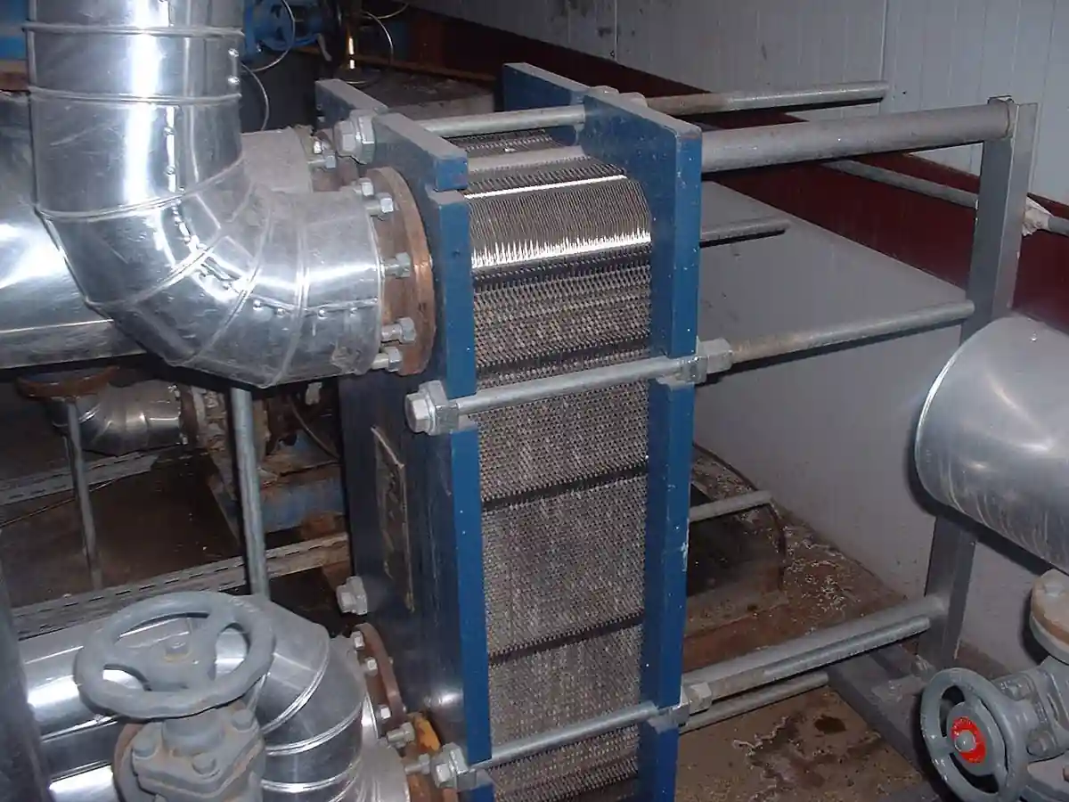
An economizer is a heat recovery exchanger mounted in a boiler's exhaust gas path that transfers flue gas heat to incoming feedwater, or to another process stream such as combustion air or makeup water, before the gas leaves the stack. The canonical build is a bank of finned or bare tubes, water inside and gas outside in crossflow, sized to pull stack temperature down from 230 to 320 deg C toward 140 to 170 deg C in a non-condensing design, and further toward 50 to 80 deg C in a condensing design that recovers latent heat from the water vapor in the gas. Every 22 deg C of stack temperature reduction returns roughly one percent of fuel input on a typical industrial boiler, which is the entire commercial logic of the machine.
Procurement engineers meet this equipment as a retrofit that pays for itself in fuel, as part of a new boiler package, and increasingly as a condensing second stage bolted ahead of an existing non-condensing economizer. The decision this page settles is narrow and practical: how much heat is actually available at what approach temperatures, whether the service allows condensing economics without condensing corrosion, which tube and casing materials survive the fuel's acid dew point, and how the bypass, cleaning, relief, and code stamping lines of an RFQ must be written so the recovered heat arrives as savings instead of as a corrosion claim in year three.
This page treats the boiler and process economizer as a purchasing object: what the flue gas can actually give up at real approach temperatures, how non-condensing and condensing stages divide the duty, why the fuel's sulfur sets the materials bill, what ASME stamping and bypass protection demand, and how the RFQ line set converts recovered heat into guaranteed savings. It is written for engineers who sign fuel budgets, not for readers who want a brochure summary.
Chapter 1 / 06
What an Economizer Is and What Is Being Decided
The machine sits in the last stretch of the boiler's gas train and steals heat the boiler proper no longer has surface to use. Flue gas leaves the boiler at 230 to 320 deg C on saturated steam and hot water boilers, and 300 to 400 deg C on many process and HRSG services. That gas still carries 8 to 15 percent of fuel input as sensible heat, and the economizer's finned or bare tube bank absorbs part of it into feedwater flowing counter to the gas, typically raising feedwater 30 to 90 deg C on its way from the deaerator to the drum. The boiler then burns less fuel to make the same steam, because the heat it would have spent warming feedwater has already been paid for once, in the gas, and is now recovered for free.
What is being decided in this purchase is a fuel savings number with hardware behind it. The vendor promises an outlet gas temperature or a heat duty at stated gas flow, inlet gas temperature, feedwater flow, and inlet water temperature. The buyer's protection is the heat balance: the quoted duty must be consistent with gas mass flow and temperature drop, water flow and temperature rise, and a gas-side pressure drop the burner and stack can tolerate. The second layer of the decision is material: the same fuel that pays for the economizer, through its sulfur and the acid dew point it creates, decides whether the cold end of the tube bank must be carbon steel, stainless, or a higher alloy, and whether a condensing stage is an economic machine or a corrosion museum.
The equipment has a place in the cycle, and its neighbors define it. Downstream in the water path, the condensate return pump and the makeup path have fed the deaerator, which has already stripped oxygen, and the boiler feed pump has raised pressure, so the economizer receives water that is chemically prepared, at deaerator outlet temperature, often 105 deg C, and pressurized well above saturation; the water-side design pressure is therefore boiler pressure, not pump suction pressure. Upstream in the gas path, the economizer is the last heat trap before the stack, sometimes after a steam separator or a blowdown heat recovery stage in the water train, and on HRSG services it sits as feedwater preheat stages alongside evaporator and superheater modules. An air-cooled heat exchanger or a dry cooler elsewhere in the plant rejects low grade heat to ambient; the economizer does the reverse, harvesting it back from gas that the plant already paid to heat.
This page locks the word economizer to the boiler and process flue gas machine. The HVAC air-side economizer is a different device that shares only the name and the philosophy: it is a damper and control logic sequence that admits cool outdoor air to a building instead of running refrigeration, and it moves air, not water through tubes. A specifier searching for boiler heat recovery who lands on rooftop damper literature has landed on the wrong page, and chapter 5 mentions that neighbor only to dismiss it. Equally, the aftercooler that cools compressed air discharge and the desuperheater that tempers live steam are adjacent heat exchangers in other services, each with its own leaf, none of them recovering boiler flue gas.
The purchase scale runs from packaged add-ons to engineered modules. A 50 to 300 hp packaged firetube boiler takes a factory economizer of a few square meters of finned surface, bolted into the stack base, with a simple bypass for low fire. A 100 t/h industrial boiler takes an engineered bank with sootblowers, casing expansion, and its own structural steel. An HRSG feedwater stage or a process gas heat recovery train is a custom module in the shell-and-tube or finned-tube vocabulary, designed with the same TEMA-informed practice as the shell and tube heat exchanger family. The RFQ discipline scales with the machine, but the physics and the failure modes below apply across the whole range.
Chapter 2 / 06
How Flue Gas Heat Recovery Sizing Works
Sizing is a heat balance fought between two approach temperatures. The gas can only be cooled to some margin above the incoming water temperature, and that margin, the terminal temperature difference or approach, is set by surface area and economics: non-condensing economizers buy approaches of 20 to 40 deg C, aggressive designs reach 15, and below that the surface cost per recovered kilowatt turns vertical. On the water side, the outlet can only approach the inlet gas temperature by a similar margin, so a 260 deg C gas stream feeding 105 deg C deaerator water delivers water in the 160 to 210 deg C band on one or two stages. The recovered duty is then simply mass flow times heat capacity times temperature change on either side, and the two must agree within the heat balance error a quotation should show.
The gas side pays for the duty in pressure drop, and the budget is tight. Burner drafting, stack draft, and fan capacity were designed without the economizer, so a retrofit bank must usually live within 25 to 75 mm of water column added resistance, with a damper or fan upgrade as the priced alternative. Gas-side velocities run 8 to 15 m/s in finned banks, high enough to sweep fouling, low enough to avoid fin erosion and vibration. Fin geometry does the area work: solid or serrated helical fins at 3 to 7 fins per centimeter multiply bare tube outside area five to twelve times, which is exactly why finned economizers can pull 300 kW out of a gas stream in a package that fits in the stack base, and why fin choice, density and height, is the main lever the vendor trades against pressure drop and cleanability.
The condensing stage changes the physics by changing the phase. When gas is cooled below its water dew point, roughly 45 to 60 deg C for natural gas combustion products at typical moisture, the vapor gives up its latent heat, about 2,260 kJ per kilogram condensed, on top of sensible cooling, and a natural gas economizer taken to 50 deg C stack temperature recovers 10 to 15 percent of fuel input where a non-condensing design recovers 4 to 7. The condensed water is acidic, carbonic and, with sulfur in the fuel, sulfurous and sulfuric, so condensing surfaces are stainless steel or higher alloy, drain paths are engineered, and the condensate is neutralized or segregated. The economics work best on clean fuels: natural gas and propane condensing stages pay back in two to five years at typical industrial fuel prices; oil and high sulfur fuels make condensing a materials problem before it is a savings machine.
The acid dew point is the sulfur boundary that non-condensing designs approach and condensing designs deliberately cross. Sulfur in fuel oxidizes to SO2 and a small SO3 fraction, which combines with water vapor to form sulfuric acid vapor; that vapor condenses onto surfaces at the acid dew point, which sits anywhere from 95 to 150 deg C depending on sulfur content and moisture, far above the water dew point. A surface below the acid dew point grows a liquid acid film, and carbon steel there corrotes at rates measured in millimeters per year. The design response is a cold end decision: keep every surface above the calculated acid dew point plus a safety margin, by feedwater temperature control, bypass, or recirculation, or build the cold end in materials that tolerate acid, 304L, 316L, or higher, with drainage. The RFQ must state the fuel's sulfur range so that this decision is made in the design office, not discovered in the stack.
Water-side limits close the sizing. Feedwater leaving the economizer must not approach steaming in the tubes: the outlet is kept some 15 to 30 deg C below saturation at the local pressure, and where loads and geometries push that limit, arrangements add recirculation or stage the bank. At the other end, the minimum feedwater temperature entering the bank is a cold end corrosion line as much as a thermodynamic one: on sulfur bearing fuels the entering water is what sets the tube metal temperature at the gas outlet, and the deaerator's 105 deg C or a recirculation loop exists partly to hold that wall above the acid dew point. Feedwater chemistry rides along throughout, hardness and oxygen controlled upstream, monitored by the conductivity meter, dissolved oxygen meter, and the analyzer family, silica, hardness, hydrazine or amine programs, that guards the boiler the economizer feeds.
The savings arithmetic deserves one honest paragraph, because it is the number the purchase stands on. Take a 20 t/h boiler at 10 bar, fuel input near 13 MW, gas leaving at 280 deg C: a non-condensing economizer sized to 160 deg C stack recovers roughly 700 to 900 kW, six to seven percent of input, and saves that fuel continuously. A condensing stage on natural gas taking the same gas to 55 deg C recovers another 400 to 600 kW and adds a condensate drain and an alloy cold end. At industrial gas prices the paybacks run one to four years, and the specification error that destroys them is not thermal; it is fouling, cold end corrosion, or a bypass strategy that leaves the bank dry and hot while the plant runs at low fire. The chapters below are about buying the savings and keeping them.
Chapter 3 / 06
Types, Construction, and Duty Boundaries
The non-condensing finned tube economizer is the standard machine. Carbon steel tubes, 50 to 80 mm outside diameter, with helical welded or brazed fins, serpentine or vertical arrays in a steel casing, feedwater inside in multipass counterflow, gas outside in crossflow. It prices per recovered kilowatt better than any other boiler room add-on, tolerates 250 to 400 deg C gas, and its whole design life argument is the cold end temperature discipline in chapter 2. Sootblowers or rappers, sonic soot cleaning, or simply generous fin spacing handle the ash; inspection ports and access doors handle the people. On clean gas services the fins run dense and serrated; on dirty gas they run sparse, plain, or the bank degrades to bare tube in the worst fouling corners.
The condensing economizer adds a second, colder stage downstream. Its architecture splits between direct and indirect families: indirect condensing units keep the water in tubes, extending the bank into stainless or alloy territory below the dew points with an integrated condensate drain and neutralization; direct contact condensing units spray water or process liquid directly upflow through packed sections of the gas, transferring heat and mass in one vessel and recovering to a lower temperature than any surface machine. The direct contact machine belongs to the scrubber and tower vocabulary, the indirect machine to the economizer's, and both earn their capital only on clean fuels and where a sink exists for low grade heat, domestic hot water, process makeup, or boiler feedwater preheat ahead of the deaerator.
Boiler-stack versus HRSG and process-gas placement divides the market by pressure and code. A packaged boiler economizer is usually within the boiler's code envelope: ASME Section I rules when it is considered boiler external piping or an integral part of the boiler circuit, with the stamping and relief philosophy that implies, or Section VIII when it is procured as a standalone pressure part. HRSG feedwater stages and process gas trains run higher pressures and engineered-module construction, with TEMA-informed shells or harp-built finned modules. The commercial difference is real: Section I stamped and boiler-mounted units arrive as part of the boiler package and its certification; standalone Section VIII units are heat exchangers in their own right, with their own documentation trail, relief devices, and the safety relief valve or equivalent protection the code demands on the water side.
The heat sink selection is a type decision disguised as plumbing. Feedwater preheat is the canonical sink and the highest value one, because every kilojoule into feedwater is a kilojoule the burner does not supply. Makeup water preheat, combustion air preheat territory when taken further, condensate polishing inlet warming, and deaerator inlet trimming are alternates with different temperature bands. When the sink is seasonal, domestic hot water in summer, or absent at low fire, the economizer needs a bypass on the gas side, a diversion on the water side, or the honesty of a design that accepts dry running, which finned banks tolerate only with materials and clearances chosen for it. The RFQ that does not state the sink's flow and temperature envelope buys a machine sized for a duty that only exists on paper.
Cleaning systems are a type line, not an accessory. On natural gas, fins mostly stay clean and inspections confirm it; on oil, biomass, and waste fuels, soot and ash build within days to the point where the fouling factor eats the design margin, and the bank needs sootblowers, steam or compressed air lancers on a timed cycle, sonic horns, or steel-shot rainers. Fouling factor selection, the design allowance for the dirty state, is a thermal guarantee line: a bank designed at 0.0017 square meter kelvin per watt dirty and quoted clean will miss its outlet temperature the first month it runs on oil. Casing design follows the fuel too: ash hoppers or drain gutters below the bank, gasketed access rows for manual cleaning, and casing insulation that keeps the gas above dew point at the walls.
Duty boundaries, stated bluntly. An economizer is not a feedwater heater in the steam extraction sense: that duty belongs to the deaerator and, on large units, to extraction heater stages in the boiler's own envelope. It is not an air preheater, which recovers gas heat to combustion air and competes with it for the same temperature band: the two split the available approach, and plants with both run the air heater first in the gas path with the economizer after, or trade one against the other by economics. It is not a condensate cooler or a blowdown flash recovery vessel, both of which are water-side machines in the steam and condensate family. And it is not the HVAC air-side economizer, a damper logic on a rooftop unit, which shares a word and nothing else. The table below consolidates the type map a specifier can carry.
Service
Construction to specify
Boundary to respect
Packaged natural gas boiler, retrofit
Non-condensing finned bank, carbon steel, gas bypass at low fire
Cold end above condensate formation; drain provision anyway
Natural gas with hot water sink available
Two stage: carbon non-condensing plus stainless condensing stage
Condensate acidity and neutralization; freeze protection
No. 2 oil fired industrial boiler
Non-condensing carbon bank, sootblowers, cold end above acid dew point
Sulfur range stated; minimum feedwater temperature enforced
Heavy oil or high sulfur fuel
Conservative approach, bare or sparse fin tubes, generous fouling factor
Condensing economics are a materials problem, not a savings one
Biomass or waste heat boiler
Engineered bank with sootblowing and hopper casing, erosion allowance
Ash fouling factor from fuel analysis, not optimism
HRSG feedwater stage
Harp built finned module to Section I or VIII, bypass capability
Steaming margin at high gas loads; water chemistry as boiler
Gas turbine exhaust, process sink
Spiral or shell-and-tube recovery module sized to sink
Belongs to the heat recovery module family when not feedwater
Chapter 4 / 06
Key Specification Parameters
The datasheet rows below decide whether a quoted economizer matches the boiler and the fuel. Each row is a purchase defining parameter; the paragraphs after the table explain what to demand and what a weak answer looks like.
Attribute
Typical range or options
What it decides
Gas flow at inlet, actual
2,000 to 200,000 kg/h boiler range
Bank size, casing, and the heat balance base
Inlet gas temperature
180 to 400 deg C by boiler type
Available duty and casing expansion design
Outlet gas temperature, guaranteed
140 to 170 deg C non-condensing; 45 to 80 condensing
The savings number and the test basis for it
Gas side pressure drop
25 to 75 mm H2O retrofit budget
Burner drafting, fan duty, and stack capacity
Feedwater flow and inlet temperature
Full boiler feed at deaerator outlet, 100 to 110 deg C typical
Approach, cold end metal temperature, and steaming margin
Feedwater outlet temperature
15 to 30 deg C below saturation at pressure
Circuit protection against steaming
Tube and fin materials
Carbon steel; 304L or 316L condensing; alloy cold ends
Life against acid dew point and condensate chemistry
Fin geometry and density
3 to 7 fins per cm; plain or serrated; bare in fouling duty
Area per meter, cleanability, and erosion behavior
Design pressure and code stamp
Boiler pressure; ASME Section I or VIII with stamping
Legal pressure boundary and relief philosophy
Fouling factor, design
0.0002 to 0.0017 m2K/W by fuel
Guaranteed performance in the dirty state
Cleaning system
None, sonic, sootblower, shot, manual access
Sustained duty between cleanings by fuel
Bypass and protection
Gas bypass damper, water recirculation, TSH control
Low fire survival and freeze and dry run strategy
The outlet temperature row is the guarantee, and it must be read with its conditions attached: gas flow, inlet temperature, feedwater flow and inlet temperature, and fouling state. A quotation of 150 deg C outlet at clean surfaces and design gas flow is a different machine from 155 deg C at the design fouling factor and minimum feedwater flow, and only the second number survives a performance test after a month on oil. Ask for the heat balance sheet, gas side and water side, and check that both sides carry the same duty within a percent or two.
The pressure drop row decides whether the retrofit works at all. The burner's fan curve and the stack's draft were bought for the boiler as it was; adding 60 mm of water column resistance on a marginal installation back-drafts the burner or chokes the firing rate, and the fix, damper, VFD fan, or stack extension, belongs in the project budget next to the economizer price. On the water side, the added circuit is short but not free: tube velocities of 0.6 to 1.5 m/s keep the feed pump in its curve and avoid deposit settling, and the bypass around the economizer for low load must be sized for full feed flow without starving the bank in operation.
The materials rows convert the fuel analysis into decade life. The table below compresses the cold end decision; the paragraph under it states the rule. Sulfur sets the acid dew point; moisture sets the water dew point; everything else is economics.
Fuel and cold end condition
Materials to specify
Watch items
Natural gas, non-condensing only
Carbon steel throughout
Still drain and inspect for intermittent condensation
Natural gas, condensing stage
304L or 316L tubes and casing wetted parts
Condensate pH 3 to 5; neutralization and materials trace
No. 2 oil, cold end above acid dew point
Carbon steel with minimum feedwater control
Sulfur range in RFQ; acid dew point calculation on file
Heavy fuel oil, high sulfur
Carbon bank with alloy outlet rows as margin
Never condense; fouling factor and sootblowing mandatory
Biomass, variable ash
Carbon or low alloy, erosion shields at inlet rows
Chloride in some ashes pushes alloy selection
Digester or process gas with H2S traces
Stainless or alloy wetted surface throughout
Dew point chemistry from gas analysis, not assumption
The rule under the table is short: calculate the acid dew point from the stated fuel range, add a margin of 10 to 20 deg C, and hold every gas-touching surface above it by feedwater temperature, recirculation, or bypass, unless the surface material is chosen and certified for the acid film it will carry. The instrumentation rows make that rule enforceable in service: a temperature transmitter on feedwater in and out and on gas in and out, a pressure transmitter or draft gauge across the bank, and condensate pH measurement on condensing stages turn the guarantee into data the plant can trend.
Chapter 5 / 06
Selection Decision Factors and RFQ Language
The decision sequence runs as a checklist, and each step eliminates a class of quotations before price comparison begins.
Fix the gas basis: flow, inlet temperature, and composition at the boiler's real operating points, full fire and the sustained low fire, because the bank must survive both ends.
Fix the fuel basis: sulfur range and moisture for dew point arithmetic, ash and sooting tendency for fouling factor and cleaning scope.
Fix the sink: feedwater or process stream, its flow and temperature envelope through the seasons, and confirm the sink exists at low fire or specify the bypass that protects the bank when it does not.
Set the economics: choose target stack temperature against the approach and pressure drop budget, and let the payback math, one percent fuel per 22 deg C, pick the size point.
Run the dew point arithmetic and make the cold end decision explicitly: above acid dew point in carbon steel, or into condensation with certified alloy and drainage.
Choose non-condensing or condensing by fuel cleanliness and sink temperature: condensing on clean gas with a cold sink is the highest return machine in the boiler room; on sulfur fuels it is a corrosion project.
Fix the code basis and relief philosophy: Section I or VIII stamping, water side safety relief valve, and gas side explosion relief where the fuel and code demand it.
Fix the verification evidence: heat balance sheet, guaranteed outlet temperature at stated fouling, pressure drop at stated flow, and the acceptance test method, gas and water side temperatures with calibrated instruments.
Against neighboring equipment, the comparison a specifier actually runs is the following, and it belongs here rather than in the page title. Against the air preheater, the two machines compete for the same gas band: the economizer returns heat to the water side and suits high feedwater approaches; the air heater returns it to combustion air and suits high burner temperature rise; large plants often buy both and sequence them. Against the condensing economizer's direct contact cousin, the spray tower and scrubber family, surface machines keep water and gas separated at higher first cost, direct contact machines recover deeper but add a water circuit. Against the deaerator, no competition exists: the deaerator removes oxygen and the economizer returns heat, and the feedwater train needs both, which is why the economizer feeds the deaerator's output forward to the drum. And once more, because the name collides: the HVAC air-side economizer on a rooftop package unit is a damper control sequence for free cooling, an entirely different device, relevant here only so that a search does not mislead a buyer into quoting rooftop dampers for boiler stack recovery.
The application map below turns those choices into a table the project file can carry into bid evaluation.
Application
Construction to specify
Check before order
Packaged gas boiler 100 to 500 hp
Factory finned bank, carbon steel, damper bypass
Fan curve headroom; low fire water flow protection
Gas boiler with 40 to 60 deg C sink
Two stage carbon plus stainless condensing
Condensate drain and neutralization; freeze design
Oil fired process boiler
Carbon bank, sootblowers, minimum water temperature interlock
Acid dew point calc from stated sulfur range
Biomass boiler, ash bearing
Engineered bank, sparse fins, shot or steam cleaning
Fouling factor from fuel analysis; erosion shields
HRSG feedwater stage
Harp module, code stamped, bypass at startup
Steaming margin analysis at maximum gas load
Steam boiler with seasonal DHW sink
Economizer plus water side diversion logic
Dry run tolerance and drain strategy in summer
The RFQ block should be written once and reused. A complete block reads: boiler or gas source with firing range; gas flow and inlet temperature at design and low fire; fuel analysis with sulfur and moisture range; required outlet gas temperature with tolerance; allowable gas side pressure drop; feedwater or sink flow, inlet temperature range, and required outlet; water side design pressure and temperature per boiler code; tube, fin, and casing materials with the cold end alloy decision; fin geometry by fouling class; fouling factor design basis; cleaning system type and utility; bypass arrangement gas and water side with control philosophy; code stamping and relief devices; instrumentation, gas and water temperature transmitters, draft indication, condensate pH if condensing; structural and casing scope with insulation and access; acceptance test method; and the documentation pack, heat balance, drawings, material certificates, and stamping papers. A quotation returned without the heat balance or with an outlet temperature quoted clean on a fouling fuel is incomplete at any price.
Chapter 6 / 06
Installation, Standards, Failure Modes, and Maintenance
Installation is duct and pipe engineering around a hot, heavy bank. The economizer mounts in the gas path with expansion provisions, bellows or sliding joints, sized for the casing growth between ambient and operating temperature; support steel carries the water-filled bank weight, often several tonnes, and the stack connection is sealed against dilution air, which both cools the gas and corrupts the temperature measurements the guarantee is read on. Water side piping follows boiler external piping practice where Section I applies: welds, supports, and the relief philosophy per code, with a bypass valve arrangement that never traps the bank under pressure without relief. On retrofits the burner and draft system are re-commissioned with the bank in circuit: fan curves verified, furnace pressure checked at full and low fire, and the gas path leak-tested.
Commissioning proves the guarantee instrumentation first. Calibrated temperature elements at gas inlet and outlet and water inlet and outlet, draft measurement across the bank, and flow reading on the water side where the project justifies it; the heat balance closes live the first day at steady fire. The bypass and interlock logic is tested at low fire: minimum feedwater flow or temperature protection, gas bypass response, and on condensing stages, condensate drainage and pH verified. A commissioning report with the four temperatures and the computed duty at two load points is the baseline the plant trends against for the next decade, and it is the document that adjudicates any performance claim.
The standards frame is code and practice. ASME Section I governs when the economizer is within the boiler's pressure envelope, with its stamping, relief, and materials traceability; Section VIII governs standalone pressure parts, with the safety relief valve or code-equivalent protection on the water side. Boiler and combustion practice, burner management and the flame supervision family, governs the gas side interlocks where the economizer affects draft or low fire operation. Water treatment practice governs the feedwater the bank carries: the chemistry monitored by conductivity, dissolved oxygen, silica, and hardness instrumentation, and the treatment programs, hydrazine or amine equivalents, that the analyzer family tracks. There is no single international economizer standard because the machine is an assembly of code parts, so the specification names the codes per part and the test method for performance.
Failure modes follow a short, predictable list. Cold end corrosion: the classic, tube wall below acid dew point from low feedwater temperature or sulfur creep in the fuel supply; symptoms are rust in condensate drains, rising pressure drop from corrosion product, and pinhole weeps at outlet rows; the fix is temperature discipline or an alloy cold end, and the cheap fix, ignoring it, ends in retubing. Fouling and soot plugging: pressure drop climbs, outlet gas temperature rises, and savings decay between cleanings; sootblower maintenance and the fouling factor honesty in design cover it. Fin erosion on ash bearing gas: inlet row fins thin and the area quietly disappears; shields and velocity limits are the cure. Steaming and water hammer in upflow banks at low flow: outlet temperature approaching saturation with insufficient velocity; recirculation, staging, or bypass logic prevents the hammer that cracks headers. Freeze damage on outdoor condensing stages in idle: drain-everything design and heat trace. Thermal cycling cracks at tube-to-header welds on cycling service: fatigue is a design and welding quality conversation held at order, not after.
Maintenance economics are mostly the cleaning and the cold end. Daily: read the four temperatures and the draft loss, and compute the live duty; a slow rise in outlet gas temperature at constant load is fouling announcing itself. Weekly on fouling fuels: verify sootblower operation and blow a bank clean. Seasonally: inspect through access doors, check the cold end rows for the acid etching signature, and on condensing stages verify drain and neutralization chemistry with a pH check. At the boiler's major inspection: internal borescope of sample tubes, wall thickness at outlet rows, fin integrity spot checks, and a decision, retube, recoat, or realloy, made on measured data. An economizer with a commissioning baseline and a trend file pays for its own vigilance, because the same data that proves the savings is the data that catches the corrosion two years early, which is how a purchasing file gets smarter instead of just older.
FAQ
How much fuel does a boiler economizer actually save?
The working rule is one percent of fuel input per 22 deg C of stack temperature reduction. A non-condensing bank taking gas from 280 to 160 deg C on an industrial boiler recovers roughly five to seven percent of input; a condensing stage on natural gas taken to 50 to 60 deg C can reach ten to fifteen percent by adding latent heat. The RFQ should attach the heat balance behind the quoted numbers, because savings are claimed at stated flows and temperatures, not in general.
What is the difference between a condensing and a non-condensing economizer?
A non-condensing bank cools gas only in the sensible band and keeps every surface above the water and acid dew points, so carbon steel serves. A condensing stage deliberately cools below the water dew point, recovering the roughly 2,260 kJ per kilogram latent heat of the condensing vapor, which roughly doubles recovery on natural gas but demands stainless or alloy wetted surfaces, drainage, and condensate neutralization. Condensing economics work on clean fuels with a cold enough heat sink; on sulfur bearing fuels the acid film makes it a materials problem first.
How does fuel sulfur decide my materials?
Sulfur oxidizes to a small SO3 fraction that combines with water vapor to set an acid dew point anywhere from 95 to 150 deg C, well above the water dew point. Any surface colder than that grows an acid film, and carbon steel there corrots at millimeters per year. Either hold the cold end above the calculated acid dew point plus 10 to 20 deg C using feedwater temperature, recirculation, or bypass, or buy an alloy cold end certified for the acid. The RFQ must state the sulfur range so the dew point is calculated, not guessed.
Can feedwater leave the economizer steaming?
No, by design. The outlet is held 15 to 30 deg C below saturation at the local pressure, because steam formation in an economizer tube causes water hammer, flow instability, and header cracking, especially in upflow banks at low load. Where geometry and load push toward steaming, the design adds recirculation, staging, or a bypass, and the control philosophy protects minimum water flow at low fire. Steaming margins are checked at maximum gas load and minimum feed flow, the worst credible corner.
Do I need a bypass damper, and what does it protect?
Almost always, on retrofit and packaged installations. At low fire the gas temperature and flow fall, the feedwater demand may disappear, and the bank can overheat, dry out, or dip its cold end below the dew points; a gas bypass damper, with water side recirculation or diversion logic, keeps the surfaces in their design band. The bypass is also the commissioning and inspection path. Its control philosophy belongs in the RFQ, because an uncontrolled bypass quietly spends the savings the machine was bought for.
What ASME stamping applies to an economizer?
It depends on the pressure boundary the purchase draws. When the economizer is procured within the boiler's code envelope, ASME Section I applies with its stamping, relief philosophy, and material traceability, and the bank arrives as part of the boiler's certification. A standalone unit procured as its own pressure vessel falls under Section VIII, with its own documentation and code-required protection, typically a safety relief valve on the water side. State the boundary in the RFQ so the stamp, the papers, and the inspector all agree before shipment.
Is an economizer in HVAC the same equipment?
No. The boiler economizer of this page is a finned tube heat exchanger recovering flue gas heat into feedwater. The HVAC air-side economizer is a damper and control sequence that admits cool outdoor air into a building for free cooling instead of running compressors; it moves air, contains no tubes, and shares only the name and the thrift. Buyers seeking boiler stack recovery who encounter rooftop damper literature are on the wrong page, and vice versa.