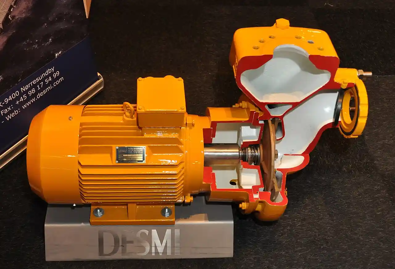
A condensate return pump lifts recovered steam condensate from low points, drip legs, and receiver tanks back to the boiler feed tank or deaerator, doing for liquid what gravity cannot do once the pressure and elevation are gone. The condensate it handles is hot and partially flashing: typically 80 to 100 deg C at atmospheric receivers, and above 100 deg C when the return system runs pressurized at 0.5 to 3 bar g. Two families cover the duty. A pressure powered unit fills a body by gravity and pushes each charge out with motive steam or air, no electricity and no rotating seals. An electric condensate unit pairs a receiver with one or two close-coupled centrifugal pumps and level controls that cycle them.
Procurement engineers meet these machines under the boiler house floor, at the base of process exchanger racks, behind injection molders and corrugators, and at the outlet of flash vessels and steam separators. The decision this page settles is narrow and practical: which family fits the plant's motive and electrical supplies, how big the receiver must be, whether the return is vented or closed, and how the package copes with stall, the low load condition where backpressure at a heat exchanger exceeds its steam supply and the exchanger floods. The answer lands as an RFQ line set: condensate load in kg/h, motive pressure or motor supply, fill head, discharge head, receiver volume, venting arrangement, and the level controls that keep the pumps honest.
This page treats the condensate return pump as a purchasing object: the fill and discharge cycle of the pressure powered machine, the NPSH arithmetic that keeps an electric condensate pump alive at 99 deg C, receiver sizing and flash steam venting, stall management, and how all of it is written into an RFQ. It is written for engineers who issue purchase specifications, not for readers who want a brochure summary.
Chapter 1 / 06
What a Condensate Return Pump Is and What Is Being Decided
The machine exists because condensate collects where pressure no longer can move it. Every steam consumer, from a shell and tube heater to a tracer line, drains through a steam trap into a return header, and the trap only passes condensate if pressure upstream of it exceeds the pressure downstream. The moment a user sits below the return header, or runs at low steam pressure, or drains into a receiver at atmospheric pressure, gravity and differential both fail and the water backs up. A condensate return pump is the machine that takes over at that point: it accepts hot condensate by gravity, holds it briefly in a receiver or pump body, and lifts it against static head, line friction, and the pressure in the feed tank. It is a low head, low to modest flow machine, and its difficulty is entirely thermal: it pumps a liquid that is at or near its saturation point and flashes at the slightest provocation.
What is actually being decided in this purchase is a system role, not just a pump. The buyer commits to a family, pressure powered or electric; to a receiver size and its venting arrangement, open to atmosphere or closed and pressurized; to a control philosophy, float cycles or level switch logic; and to the interfaces at both ends, what drains into the unit and what it discharges into. A condensate transfer pump chosen only on flow and head will still fail if the fill head is too small, if the motive steam is wet, if the vent line is undersized, or if the discharge check valve slams on every cycle. Those four failure paths account for most of the callback volume in this product class, and all four are decided on paper before anything is ordered.
Two boundaries must be drawn at the start because two neighbors share words with this page. A condensate pot is a small sealed vessel in instrument impulse lines, the pot that holds a stable condensate seal for steam side differential pressure measurement on flow or level loops; it has no moving parts, pumps nothing, and its only job is to keep hot condensate standing in two small tubes. A boiler feed pump is the high head machine that takes water from the feed tank or deaerator and raises it to drum pressure; it sits downstream of everything this page describes and typically demands an NPSH study of its own. The condensate return pump is the low head collection link between the two: drains in, feed tank out, with the boiler feed pump doing the pressure work afterward.
The system context usually includes four neighbors worth naming in the RFQ. Upstream, each steam trap passes condensate and holds steam, and a steam separator at major users knocks entrained droplets out of the supply line so the traps see less carryover. On vacuum deaerator trains, a steam ejector holds the deaerator below atmospheric pressure and its aftercondensate drains back into the same collection system. Downstream of the receiver, the boiler feed pump draws from the tank the return pump fills. A package quotation that ignores those interfaces, trap backpressures, separator drains, ejector load, feed tank pressure, is a box price, not a condensate system.
Four standards and references organize the datasheet. Pressurized receivers are pressure vessels and fall under ASME VIII or the European PED, with the stamp or CE marking and relief protection to match. ASME PTC 39 gives the performance test code context for condensate and feedwater systems. Pump end construction, test, and NPSH reporting follow the Hydraulic Institute standards, and manufacturer technical information sheets, the Spirax Sarco TI documents in the sources list are the model, publish the capacity and motive data a specification should demand. A datasheet that quotes none of these is a price tag, not a specification.
Compressed to one sentence, the RFQ decision is whether recovered condensate is lifted by motive pressure in cycles or by a motor through a low NPSH impeller, with a receiver sized for real load swings, a venting strategy matched to the flash steam, and stall behavior understood at the worst user, or whether a receiver and a pump are bought separately and hoped together. The chapters that follow supply the cycle physics, the datasheet rows, the selection logic, and the failure modes needed to write it the first way.
Chapter 2 / 06
How Pressure Powered and Electric Units Move Hot Condensate
The pressure powered pump is a cyclic machine with exactly one moving mechanism and no rotating seals. Its body fills by gravity through an inlet check valve while a float rises with the liquid level. At the full level the float mechanism snaps the motive valve open, admitting steam or compressed air above the liquid, and the body pressure closes the inlet check valve and drives the charge out through the discharge check valve into the return line. When the body has emptied, the float drops, the motive valve shuts, the body vents back to the receiver, and the cycle restarts. Nothing rotates, nothing needs an electric supply, and the pump works in washdown areas, explosive atmospheres, and deep basements where a motor would need special treatment. Its output is intrinsically intermittent: capacity equals the usable body volume multiplied by cycles per hour, and families of this design cycle up to a thousand or more times per hour, so a single mid-size body moves on the order of one to thirty m3/h of condensate depending on size and motive conditions.
The motive side is where pressure powered units are won or lost. Motive pressure must exceed the maximum discharge backpressure with a real margin: a working floor of about 1 bar above backpressure, with efficient cycling typically wanting 2 to 4 bar of margin, and common plant practice running motive steam at 1 to 10 bar g above whatever the discharge line and feed tank impose. Where the only steam available is far above the requirement, a pressure reducing valve conditions the motive supply to the band the mechanism likes, and a small ball valve isolates the motive line for maintenance. Wet motive steam erodes the mechanism and waters the condensate, so the motive takeoff should come from the top of the header, and a Y strainer on the motive line stops the scale that wedges the motive valve. Compressed air, inert gas, or pressurized water can all serve as motive where steam is unavailable, at the cost of more energy per kilogram lifted.
The thermal core of every condensate system is flash steam, and the arithmetic belongs in every specification file. When condensate saturated at steam supply pressure drops to receiver pressure, part of it flashes: the flashed fraction, in words, is the drop in sensible heat of the liquid between the two pressures divided by the latent heat at the receiver pressure. Condensate released from 5 to 10 bar g to an open receiver flashes roughly 10 to 16 percent of its mass as steam, which is why an open receiver on a 6 mm vent is a steam plume generator and why the vent line is sized for flash steam, not for air. A vented receiver deliberately lets that steam go, or recovers it through a vent condenser; a closed receiver held at 1 to 3.5 bar g keeps the water above 100 deg C, retains the flash as system pressure, and feeds less oxygen to the metal, but every component downstream then carries a pressure rating. The choice between vented and closed is therefore an energy decision, a corrosion decision, and a vessel rating decision at once.
The electric condensate unit attacks the same duty with a centrifugal pump end, and its physics is the NPSH problem. Water at 95 to 99 deg C has a vapor pressure within a few kilopascals of atmospheric, so the only suction head available is the static fill height above the pump inlet, minus suction line friction, and pumps built for this service use oversized, low NPSH first-stage impellers to convert that thin margin into reliable operation. Practical installations want 0.3 to 1 m of fill head from receiver minimum level to pump centerline, and the vendor's NPSH required curve at the operating point must sit below that available head with margin. A level switch or float alternator starts the pump at high level and stops it at low level so the pump never runs dry, and twin pump duplex sets alternate lead and lag so wear divides evenly and one pump can be serviced while the other holds the plant.
The numbers that define an electric package are modest and easy to check. Flows run 0.5 to 20 m3/h with heads of 10 to 40 m across the common catalog families, which is exactly the band between a receiver in the basement and a feed tank one or two floors up. Receivers on packaged units span roughly 30 to 1,000 L by frame size, and closed versions are rated to about 3.5 bar g with the appropriate code stamping. Because the machine cycles on level, its pump capacity is bought above the condensate load, commonly 1.5 to 2 times the incoming load, so the receiver empties faster than it fills and the duty factor stays sane. The same arithmetic, load, diversity, receiver minutes, appears in chapter 5 as the sizing spine of the RFQ.
Stall is the failure mode that decides whether any return pump is needed at all on temperature controlled exchangers. A steam trap only passes condensate when steam pressure at the trap exceeds the backpressure beyond it. As control valves throttle the steam supply at low load, the pressure upstream of the trap falls until it equals the combined return header and static backpressure, and at that instant drainage stops and the exchanger floods, oscillating water temperature and hammering coils. The standard fixes are to lower the return pressure, to drain the exchanger through a pump, or to fit a combination body that behaves as a steam trap at normal load and as a pressure powered pump when the differential disappears, which keeps the heater draining continuously across the whole control range. Stall analysis, steam supply pressure at minimum load against backpressure at the user, is a datasheet exercise the return pump purchase should force, not follow.
Chapter 3 / 06
Types, Construction, and Duty Boundaries
The single pressure powered body is the atom of the first family: a cast iron, cast steel, or stainless steel vessel with inlet and outlet check valves, a float mechanism, and a snap action motive valve, sized by body volume and motive conditions rather than by impeller geometry. Bodies are commonly DN 25 to DN 100 connections spanning a few hundred kilograms per hour up to tens of thousands on large sizes, and the same body runs on steam, compressed air, or gas motive as the plant allows. Units are frequently duplicated in duplex arrangement with common inlet and outlet headers so one body services while the other cycles, and packaged versions add a vented receiver, level sight glasses, and motive conditioning on one skid, the packaged unit documents in the sources being representative.
The second family is the electric packaged condensate unit: a receiver, cast iron or fabricated steel and often epoxy lined, with one or two close-coupled or frame mounted centrifugal pumps below or beside it, a level switch or float column controlling them, and a discharge manifold with check valves and isolation. Vented units breathe to atmosphere through a vent sized for flash steam, with an air release valve at the receiver high point to clear non-condensables at startup on some builds. Closed units seal the receiver, rate it as a pressure vessel with a safety relief valve, and often fit a vent condenser to recover flash steam into the feedwater instead of losing it over the roof. Twin pump sets alternate automatically; single pump small sets cycle against the receiver volume.
The pump and trap combination body deserves separate attention because it removes stall rather than tolerating it. In normal differential operation a float mechanism holds the unit in trap mode, passing condensate through a conventional orifice path. When differential collapses at low load, the mechanism switches to pump mode and motive pressure pushes the accumulated condensate out against the backpressure, then reverts. On temperature controlled heat exchangers, sterilizers, and coils that must drain at every load, this single body replaces the trap plus pump plus receiver arrangement that stall otherwise forces on the plant.
Duty boundaries keep the two families honest. The pressure powered unit is the default wherever electricity is unwelcome, where condensate arrives at full steam temperature with heavy flash, or in vacuum systems where a centrifugal suction would cavitate regardless of fill head; it tolerates abuse, freezes safely if drained, and its consumables are a mechanism kit and check valves. Its costs are motive energy, which is real steam or air spent lifting water, and cyclic flow in the discharge line, which must be designed against water hammer. The electric condensate unit is the default where energy cost dominates, where flow is steady and large, and where fill head is available; it is continuous, quiet in the hydraulic sense, and efficient, but it demands NPSH discipline, clean level controls, and mechanical seal care at temperature. Neither family pumps steam: a receiver that arrives full of flash steam rather than water is a venting and condensing problem, not a pumping one.
The type table compresses the family into the form a specification meeting argues from; values are common spans of the established families and must be confirmed against the manufacturer datasheet before order.
Type
Construction
Capacity and head class
Duty it wins
Single pressure powered body
Cast iron or steel vessel, float mechanism, motive valve, check valves in and out
Hundreds of kg/h to 20,000 kg/h class by size; discharge head set by motive margin
High temperature condensate, no-electric areas, vacuum drainage
Duplex pressure powered set
Two bodies on common headers, alternating service
Same body range, doubled availability
Continuous plants that cannot stop condensate handling
Packaged vented unit with receiver
Body plus vented receiver and motive conditioning on a skid
Receiver 30 to 1,000 L family; flash vented or condensed
Central collection of trap and separator drains
Pump and trap combination body
Trap mode at normal differential, pump mode at stall
Exchanger drain sizes, DN 25 to DN 100 class
Temperature controlled exchangers that must drain at all loads
Electric packaged unit, single pump
Vented receiver, one low NPSH centrifugal pump, level control
0.5 to 10 m3/h at 10 to 40 m typical band
Steady loads with motor supply and fill head available
Electric packaged unit, twin duplex
Receiver plus two pumps, automatic alternation, check and isolation manifold
2 to 20 m3/h at 10 to 40 m; 100 percent standby
Central boiler house return with maintenance continuity
Closed, pressurized electric unit
Pressure rated receiver to 3.5 bar g with safety relief valve, vent condenser options
Same pump band, condensate held above 100 deg C
Energy recovery of flash steam and oxygen exclusion
Chapter 4 / 06
Key Specification Parameters
The datasheet rows below decide whether a quoted unit matches the duty; values are stated as the common industrial spans of the established families and must be confirmed against the manufacturer capacity and motive data before order.
Attribute
Typical range or options
What it decides
Condensate load
Hundreds of kg/h to 20,000 kg/h class; specify with 1.5 to 2x diversity
Body size or pump capacity and the receiver duty cycle
Discharge head requirement
10 to 40 m family: static lift plus line friction plus feed tank pressure
Pump duty point or required motive margin
Motive pressure available
1 to 10 bar g above maximum backpressure, 2 to 4 bar efficient margin
Whether pressure powered cycling is feasible and fast
Fill head, electric sets
0.3 to 1 m minimum level to pump centerline
NPSH margin against the vendor NPSHr curve at temperature
Condensate temperature
80 to 100 deg C vented; above 100 deg C closed systems
Vented or pressurized receiver and elastomer limits
Receiver volume
30 to 1,000 L family, 5 to 10 minutes at load
Cycle frequency, reserve against load swings
Receiver pressure rating
Atmospheric vented; to 3.5 bar g closed, ASME VIII or PED
Low NPSH impeller, 0.5 to 20 m3/h at 10 to 40 m, 2 to 4 pole motors
Energy use, seal service, tolerance of the hot water
The load row is the one most often written wrong. Condensate loads swing with the seasons, the batch schedule, and the warmup transient, and a return pump bought on the average load drowns at warmup while a pump bought on the connected load cycles itself to death in summer. The honest method is the expected steady load with a 1.5 to 2 diversity factor for the pump capacity, plus a receiver sized to absorb the swing, 5 to 10 minutes of condensate at normal load for electric sets and the body fill cycle for pressure powered units. The discharge head row must be built from the three real components, static lift from receiver to feed tank, friction at the pumping rate, and the pressure above the water in the tank or deaerator, and the deaerator pressure is the one component habitually forgotten on pressurized units.
The family table below puts the two architectures against each other on the axes a purchase actually turns on; the fuller selection narrative lives in chapter 5.
Attribute
Pressure powered unit
Electric condensate unit
Energy input
Motive steam or air per cycle; steam spend visible in the balance
Motor kilowatts, roughly 0.37 to 7.5 kW across the family band
Flow character
Intermittent slugs, discharge line needs hammer design
Continuous while running, smooth line hydraulics
Temperature ceiling
Saturated condensate at motive conditions; flash tolerant
95 to 99 deg C on low NPSH builds with proper fill head
Electrical requirement
None at the pump; controls only
Motor supply and level controls mandatory
Rotating seals
None; snap mechanism and check valves only
Mechanical seal at temperature, a scheduled service item
Vacuum and low NPSH duty
Preferred; fills by gravity, pushes by pressure
Poor fit; cavitation risk regardless of fill head
Maintenance center
Motive valve mechanism, check valve seats
Seal, level switch cleaning, bearing set
Instrumentation rows decide whether the unit reports its own health. A level switch gives two state control; a level transmitter gives continuous level, and on any unit that matters it feeds the alarm band, the cycle counter, and the trend that shows a fouling float before it shows a flooded basement. A temperature transmitter on the receiver or discharge catches both flash behavior and seal distress on electric sets, and a pressure transmitter on the discharge line confirms the backpressure the unit actually works against, which is the number the stall analysis assumed. Vented receivers deserve a working vent and a sight glass; closed receivers deserve the pressure gauge, a properly set safety relief valve, and code documentation. Where the wider loop meters flash or vent steam with an orifice and a DP cell, each impulse line holds a standing condensate pot to keep the measurement honest, a small sealed neighbor that shares the name and nothing else. What the datasheet must state in plain terms: capacity at stated motive or at stated speed, motive pressure band, fill head requirement with the NPSH margin at temperature, receiver volume and rating, materials, control logic, and the expected cycles per hour or pump starts per hour, because that number is the wear clock of the whole machine.
Chapter 5 / 06
Selection Decision Factors and RFQ Language
The selection sequence runs as a checklist, and each line eliminates a class of quotations before price comparison begins.
Fix the condensate load honestly: steady load, warmup peak, and the diversity factor applied, in kg/h, because every downstream line follows this number.
Fix the energy context: available motive pressure and quality for pressure powered units, motor supply for electric sets, and the relative cost of steam and electricity on this site.
Compute the discharge head from static lift, line friction at pumping rate, and feed tank or deaerator pressure, and state it as meters of water on the datasheet.
Decide vented or closed return: flash recovery and oxygen control against vessel rating and control complexity.
Check the electric option for NPSH: fill head available from the installation geometry against the NPSHr curve at condensate temperature.
Run the stall check at the worst user: minimum load steam pressure against return backpressure, and choose a pump and trap combination body where drainage would stop.
Size the receiver: 5 to 10 minutes at load for electric sets, body fill and cycle rate for pressure powered, with the vent or relief sized for flash.
Fix the controls and instrumentation: level device, alternation logic, alarms, and the temperature and pressure readings the commissioning file will baseline.
Against the neighboring approaches, the comparison a specifier needs runs as follows, and it belongs here in the selection chapter rather than in a page title. Pure gravity return, draining every steam trap into an overhead header with enough fall, is free of machinery and should be used wherever the building allows; the return pump exists only where fall or backpressure fails it. Between the powered families, the pressure powered unit spends motive steam or air, and its honest economics depend on how much flash it would otherwise waste and how expensive electricity is; the electric condensate pump spends kilowatts but pumps continuously and cheaply, and repays its seal and level discipline on any steady load above a few cubic meters per hour. A steam condensate pump of the combination type competes not on energy but on drainage certainty, holding exchanger heat transfer at minimum load where a trap alone stalls. Upstream hardware sets the pump's incoming water quality: every steam trap, the steam separator at major users, and the drains of a vacuum system's steam ejector all land in this receiver, and their combined flash and non-condensable load sizes the vent. Instrumented alternatives, an orifice continuous bleed or a control loop with a flow meter and a globe valve, belong to other duties and other pages; collection and lift is this page's job.
The application map below compresses the practice into the form a project file carries.
Application
Construction to specify
Check before order
Boiler house central return station
Twin duplex electric unit, 100 percent standby, level transmitter with alternator
Fill head at temperature; deaerator pressure in the head calculation
Remote process bay without motor supply
Single pressure powered body on a small vented receiver
Motive margin over backpressure; motive line strainer and trap drainage
Temperature controlled heat exchanger with stall risk
Pump and trap combination body at the exchanger drain
Minimum load steam pressure against return backpressure
Flash vessel recovery duty
Pressure powered unit below the flash vessel, closed where possible
Body sizing at the flash vessel pressure, not atmospheric
Corrugator or molder zone drainage
Vented electric package, epoxy lined receiver, air release valve on the high point
Cycle rate at warmup; seal plan for 90 deg C plus service
Vacuum deaerator condensate
Pressure powered unit, capable of lifting from sub-atmospheric suction
Steam ejector aftercondenser drain routing and non-condensables
High rise building condensate
Closed pressurized return with code rated receiver and vent condenser
Safety relief valve set and certified; oxygen control treatment
The RFQ block should be written once and reused. A complete block reads: condensate load in kg/h at steady and warmup, with the diversity factor stated; motive medium and pressure band, or motor supply and rating; fill head or suction arrangement actually available, with condensate temperature; discharge head broken into static, friction, and tank pressure components; receiver volume and venting arrangement, vented or closed with the rating and code, ASME VIII or PED, required; wetted materials and lining; control logic, float mechanism or level switch or level transmitter, duplex alternation, and alarm list; instrumentation to be supplied, temperature transmitter, pressure transmitter, and gauge locations; the valve set, discharge check valve, isolation ball valve, motive isolation with pressure reducing valve and Y strainer where applicable, sampling globe valve, and the safety relief valve for closed sets; and the verification evidence expected, capacity at stated conditions, cycle rate or starts per hour, NPSH margin statement for electric sets, and the manufacturer technical information sheets behind every quoted number. A quotation returned without the capacity basis or the NPSH statement is incomplete at any price.
Chapter 6 / 06
Installation, Standards, Failure Modes, and Maintenance
Installation quality decides whether the unit reaches its mechanism life instead of its callback life. For pressure powered units, the body must sit low enough to fill by gravity from the receiver or drain header, with the shortest practical suction drop and an inlet check valve that seals; the motive line takes its supply from the top of the steam main, through a Y strainer and, where the header is far above the requirement, a pressure reducing valve set into the band the mechanism wants, with a ball valve for isolation and a steam trap at the motive takeoff drip leg so wet steam never reaches the motive valve. The discharge line must be designed for slugs: as short and as straight as possible, anchored, rising without pockets, with the check valve close to the pump outlet and an air release valve at any high point where gases would otherwise collect. The vent or balance line back to the receiver is part of the pump, not an optional pipe, because the body must vent to refill.
For electric sets, the fill head rule is absolute: the pump centerline sits at least the vendor's stated distance below the receiver's minimum working level, the suction line is one or two sizes larger than the pump inlet and runs uphill to the pump with no high points, and a basket or conical strainer protects the impeller from the weld bead and gasket cuttings that every commissioning produces. Receivers breathe correctly or corrode: an open vent sized for flash steam, a sight glass or level transmitter the operator actually reads, and on closed sets the code documents, the safety relief valve, and the pressure gauge within calibration. Level controls stay clean: the float column or level switch sits where solids settle elsewhere, and the alternator gets exercised on a schedule so the standby pump is a fact rather than a hope.
Commissioning earns the guarantees. On a pressure powered unit, time the fill and discharge strokes against the datasheet cycle rate with a watch and record motive pressure from a pressure transmitter or gauge at the valve, because slow cycling with healthy motive means a worn mechanism or a partially blocked strainer, and fast cycling with weak discharge means backpressure eating the margin. On electric sets, capture the first cycle from cold: start level, stop level, discharge pressure from the pressure transmitter, motor current, and casing temperature from the temperature transmitter, and file all of it as the baseline. Check the discharge check valve for slam by listening at shutoff, and verify water hammer is absent at maximum cycle rate before anyone signs the certificate. On combination bodies, prove both modes deliberately, trap mode at normal differential and pump mode at simulated stall, rather than accepting the demonstration at one operating point.
The standards frame is compact and mostly inherited from the vessel and pump worlds. Receivers under pressure are vessels: ASME VIII stamping or PED conformity with CE marking, relief protection sized for the credible overpressure, and periodic inspection under the local pressure equipment rules. Pump ends on electric sets follow Hydraulic Institute construction, test, and NPSH reporting practice, and the motor follows its own IEC 60034 or NEMA MG 1 frame. ASME PTC 39 provides the performance test context for condensate handling systems where a formal acceptance test is contractual. Local codes add vent discharge rules for flash steam and, on closed systems, backflow prevention between the receiver and the treated feedwater. Naming the standards in the RFQ moves the burden of proof to the supplier, where it belongs.
Failure modes follow a short and predictable list. On electric sets, cavitation from insufficient fill head or hot condensate at the suction kills mechanical seals first: symptoms are noise at low receiver level and short seal life, and the fixes are level, suction piping, or impeller selection, in that order. Level switch fouling runs pumps dry or floods receivers: clean the column on a schedule and alarm on level high, not on the janitor. On pressure powered units, motive valve mechanism wear shows as slow or failed cycling, discharge check valve wear shows as slam and backflow hammer, and a motive line without its Y strainer delivers scale that accelerates both. Receiver corrosion and oxygen pitting attack open vented systems from the water line upward: the countermeasures are lining, chemical oxygen scavenging agreed with the water treatment program, and the shortest possible storage time, which is exactly what the 5 to 10 minute receiver sizing already enforces. On combination bodies, the mechanism kit is the consumable and the check valves are the witnesses.
Maintenance intervals scale with duty severity. Daily: a glance at cycle behavior or pump starts, and vent condition on vented receivers. Weekly: motive strainer differential on dirty steam systems, level device indication against the sight glass, and any logged temperature trend review. Quarterly: check valve seat inspection on cycling duty, mechanism link inspection on pressure powered units, and alternator exercise. Annually: receiver internal inspection for pitting and scale, seal inspection or exchange on electric sets, relief valve test on closed systems, and a full stroke timing against the commissioning baseline. Spares on site: one mechanism kit and one set of check valves for each pressure powered body, one seal assembly and one level switch for each electric set, and the gaskets that match the receiver inspection. Held to that rhythm, the unit becomes the quietest machine in the boiler house.
FAQ
Should I choose a pressure powered or an electric condensate pump?
Choose pressure powered when motive steam or air exists, when condensate arrives near saturation with heavy flash, when the area forbids electrical equipment, or when the suction is under vacuum; it cycles without seals and tolerates heat that starves a centrifugal pump. Choose an electric condensate pump when flow is steady, fill head exists, and energy cost dominates, because the motor lifts water far more cheaply than motive steam. Many plants run both: electric at the central station, pressure powered at remote and hot points.
How do I size the receiver on a condensate unit?
Size the receiver for 5 to 10 minutes of condensate at normal load, then check it against the swing between warmup and minimum load. The pump capacity, not the tank, handles the peaks, and it should sit at 1.5 to 2 times the steady condensate load so the receiver empties faster than it fills. A tank sized on connected load merely stores water, cycles the level controls to death, and gives oxygen more contact time with the metal, which the corrosion chapter of every water treatment program warns against.
What fill head does an electric condensate unit need?
Plan 0.3 to 1 m from the receiver minimum level to the pump centerline, then verify against the vendor's NPSH required curve at your condensate temperature. At 95 to 99 deg C the vapor pressure nearly equals atmospheric pressure, so that static height, minus suction line friction, is effectively all the NPSH the pump gets, which is why these machines use low NPSH impellers. Undersizing the fill head does not show up in the flow test; it shows up six months later as a failed mechanical seal.
What is stall, and how does a condensate pump fix it?
Stall is the condition where backpressure at a heat exchanger drain equals or exceeds the steam pressure upstream of its steam trap, usually at low load when the control valve throttles the supply. Drainage stops, the exchanger floods, and temperature control oscillates. A pump and trap combination body fixes it by switching to pressure powered pumping whenever the differential collapses, so the heater drains at every load. Alternatively, the exchanger drains to a low level receiver and a separate condensate return pump lifts it onward.
Can a condensate return pump handle condensate above 100 deg C?
Yes, but only inside the right construction. Pressure powered units push saturated condensate without difficulty because they have no suction in the centrifugal sense. Electric sets need either generous fill head with a low NPSH impeller or, better, a closed pressurized receiver rated to about 3.5 bar g, which keeps the water subcooled relative to its own pressure, retains the flash steam as useful energy, and excludes the oxygen that drives return line corrosion. An open receiver above 100 deg C is simply a vent stack.
Why does our electric condensate unit cavitate and fail seals?
Three usual causes. First, fill head eroded by design changes or a lowered minimum level, so the NPSH margin at temperature disappears. Second, long or restricted suction lines with a strainer that no one cleans, eating the small head available. Third, hot condensate plus a mechanical seal without a flushing or quench plan suitable for the temperature. Fix level and piping before blaming the pump, then specify a seal plan matched to the duty, and trend the discharge temperature transmitter so distress appears as data before it appears as downtime.
What must the RFQ state for a condensate return pump package?
State the condensate load in kg/h with the diversity factor, motive medium and pressure band or the motor supply, the available fill head with condensate temperature, and the discharge head split into static, friction, and feed tank pressure. Add receiver volume, vented or closed arrangement with the vessel code required, wetted materials, control logic with alarms, and the instrumentation list, level device, temperature and pressure readings. Demand the capacity basis and, for electric sets, the NPSH margin statement, with the manufacturer data sheets attached to the quotation.