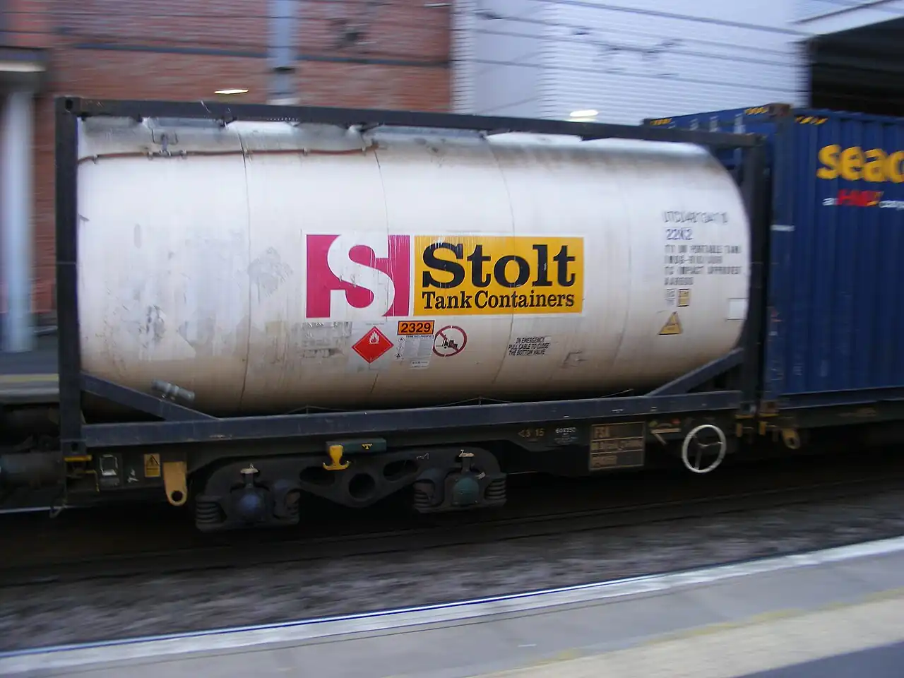
An air receiver, also called an air receiver tank or compressed air receiver, is the pressure vessel installed in a compressed air system to store air, buffer demand swings against compressor capacity, and settle out condensate. Compressed air is the only plant utility that is produced, stored, and consumed at different rates by design: the receiver is the reservoir that lets a fixed compressor ride through short high demand events without starting standby machines, damps the pressure pulsations a reciprocating machine feeds into the piping, and gives water vapor a cold, quiet volume to condense in ahead of the dryer. Vessels run from 30 liters under a small piston compressor to 30,000 liters and more at plant scale, vertical or horizontal, built to ASME Section VIII or the PED, and fitted from birth with the hardware that keeps a stored-energy vessel honest: safety relief valve, pressure gauge, drain, and inspection openings.
Procurement engineers meet this vessel when specifying a compressor station, when fixing a plant's pressure stability problems, and when an inspection audit finds the existing tank out of code. The decision this page settles is narrow and practical: how much volume the duty actually needs, where the tank sits in the train, wet before the dryer or dry after it, which code and fittings the jurisdiction demands, and how drains, corrosion allowance, and installation details make the difference between a 10 year tank and a 30 year tank. The answer lands as an RFQ line set: volume, working pressure, code, wet or dry placement, orientation, drain type, and fittings. Every chapter below feeds that line set so the stored energy asset is bought on arithmetic, not on a tank catalogue's diameter column.
This page treats the air receiver as a purchasing object: what storage volume actually buys in control stability and standby avoidance, how wet and dry placement differ in condensate and dryer duty, what the codes demand of a stored energy vessel, and how drains, corrosion allowance, and installation details combine into a defensible RFQ. It is written for engineers who issue purchase specifications, not for readers who want a brochure summary.
Chapter 1 / 06
What an Air Receiver Is and What Is Being Decided
Compressed air systems fail quietly in the gap between production and demand. A compressor is a machine with a capacity curve; a plant is a population of users with a demand profile that spikes when a sandblast nozzle opens or a cylinder fires. Without storage, every spike propagates straight to the compressor controls: pressure sags, standby machines start for twenty seconds, and the whole station hunts. The receiver inserts volume between the two, and the volume converts flow mismatch into a slow, manageable pressure change instead of a control event. The same volume, on a reciprocating machine, absorbs the discharge pulsations that would otherwise shake the piping apart, and on any machine gives the hot discharge air a moment to cool so that water vapor condenses in the tank instead of in the dryer or, worse, in the user's equipment.
What is actually being decided in this purchase is stored energy with a purpose. The buyer commits to a volume, a working pressure, a placement in the train, and a code package, and the volume is the interesting decision because it is the one arithmetic buys. Too little storage and the plant lives with hunting compressors and dew point excursions; too much and the capital, floor space, and the drained condensate inventory all grow for events that never happen. The honest sizing basis is the plant's real demand profile, the compressor station's control bands, and the events storage is asked to ride through, and every one of those numbers exists in the plant's data or in the design brief before the first quotation is requested.
The train context matters because the receiver is one station in a chain of machines, and its neighbors must not be confused with it. Upstream, the compressor itself, a screw-compressor or reciprocating-compressor or centrifugal-compressor machine whose capacity and control mode fix what the receiver rides through; a scroll-compressor or diaphragm-compressor appears at the small and high purity ends. Between compressor and receiver, or right at the receiver inlet, the aftercooler knocks the bulk of the water out with cooling, and the receiver settles what follows. Downstream, the air-dryer, refrigerated or desiccant, whose inlet flow smoothing the receiver protects, the coalescing-filter and industrial-filter stages that clean the air, and the pressure reducing valve stations that serve low pressure users. The nitrogen-generator on the same plant air feed draws through its own receiver logic, and the sister vessel treated on its own page, the hydronic expansion-tank, stores water volume for a heating loop rather than air for a plant: same code family, different physics, different purchase.
Standards organize the datasheet. The pressure boundary is governed by ASME Boiler and Pressure Vessel Code Section VIII Division 1 in North American practice and by the Pressure Equipment Directive with its harmonized standards in Europe, and the stamp or CE marking carries the category, the design conditions, and the inspection regime with it. The Compressed Air and Gas Institute, CAGI, publishes the application guidance the industry quotes on storage and control, including the classic treatments of storage on reciprocating installations. Piping connections follow standard flange or threaded practice, and the safety relief valve follows the applicable pressure relief standard as part of the vessel package. Local installation codes add seismic, drainage, and location rules. A datasheet that quotes no code of construction is a price tag, not a specification.
The RFQ should also name the operating environment, because it changes the vessel. A tank outdoors in a coastal yard wants external coating and internal corrosion margin for condensate that will sit in it; an indoor clean utility tank wants a drainable low point and, in food or pharma plants, the material and finish approvals of that industry; a seismic site wants the support calculations that anchor the vessel to the slab. The instrument list, a pressure gauge and switch or transmitter for station control, completes the picture. Stating these in the RFQ lets one supplier quote the vessel and its fittings as a package instead of a shell with an accessories argument attached.
Chapter 2 / 06
How Storage Volume Buys Stability
The arithmetic of storage is one equation wearing several costumes. The air released by a volume dropping from one pressure to another is proportional to the volume and to the pressure difference, corrected by atmospheric pressure: a 5,000 liter receiver falling from 8 bar to 7 bar gauge releases roughly 5,000 liters of free air, and the plant that draws 3,000 liters per minute rides that fall for a minute and a half before the compressor must respond. That single line of mathematics answers the three classic sizing questions: how long storage carries a spike, how far pressure falls during it, and how often a standby machine starts. Every rule of thumb the industry quotes, gallons per compressor horsepower, seconds of storage per unit flow, is this equation folded into a constant, and the buyer who runs the equation directly gets an answer with the plant's real numbers in it instead of an average plant's.
Control bands decide how much of the stored air is usable. A screw compressor station on load and unload control cycles between two set points, and only the band between them is working storage: a wide band uses the receiver harder and saves starts, a narrow band holds pressure tighter and spends starts instead. Modulating and variable speed controls change the story, and the variable frequency drive, the vfd in the electrical room, turns the same volume into a slower, deeper buffer because the machine can track demand instead of switching. The receiver volume and the control band are one decision split in two, and the specification that fixes one without the other buys half an answer.
Pulsation damping is the second service the volume performs, decisive on reciprocating machines. A piston compressor discharges in slugs, and the piping downstream of it sees pressure waves that fatigue welds and rattle instruments; the receiver is the acoustic volume that absorbs them, which is why the classic CAGI treatments of reciprocating installations treat storage and pulsation together. Sizing for pulsation follows the machine's excitation and the line's acoustic response, and the practical form of the answer is that the receiver sits close to the compressor, connected by a short, generously sized line, so the waves die in the vessel rather than in the pipe rack. Centrifugal machines bring their own counterpart, surge control, where storage interacts with the machine's surge line, and the receiver and blow-off logic protect the machine exactly as the controls textbook says.
Condensate settling is the quiet third service. Compressed air leaves the aftercooler near saturation, and every degree it cools in the piping drops water; the receiver, being the largest cool volume in the train, is where a meaningful share of that water condenses and, just as important, where it collects in a designed low point with a drain, instead of migrating to the dryer or the tools. This is the wet side of the wet versus dry placement question that chapter 3 develops: the tank that sits before the dryer collects aggressive, oily condensate and earns its corrosion allowance, while the tank after the dryer sees dry air and serves a pure storage duty. The drain choice, manual, timed, or zero-loss, decides whether the collected water actually leaves.
Two verification numbers decide whether the installed receiver performs. The first is the usable storage delivered at the plant's control band, which is a computed figure the supplier should confirm against the vessel's actual geometry. The second is the pressure drop between compressor and system header: a receiver connected through an undersized line strangles the volume it exists to provide, and the connection sizing belongs in the specification, not in the installer's judgment.
Chapter 3 / 06
Wet and Dry Placement, Construction, and Code Fittings
Placement is the first fork. The wet receiver sits between compressor or aftercooler and the dryer: it collects the condensate and oil that would otherwise load the dryer, buffers the pulsations at their source, and lets the dryer see a steadier, cooler flow. The dry receiver sits after the dryer and filters: it stores clean dry air for the sharpest demand events, holding the dew point through a spike that would momentarily overwhelm the dryer's capacity. Many plants run both, and the honest division of labor is that the wet tank protects the dryer and the dry tank protects the point of use. A system with one tank must choose which duty matters more, and the choice belongs in the design brief, because it changes the vessel's corrosion exposure and its drain story in opposite directions.
Construction follows the code and the site. Vertical receivers dominate plant installations: smallest footprint, natural condensate collection at the bottom head, and level and pressure instruments reading from predictable nozzles. Horizontal receivers appear under mezzanines and outdoors where height is constrained, and they trade footprint for the plumbing details that keep their low point drained. Materials are steel in the overwhelming majority, painted externally and either painted, galvanized, or epoxy lined internally against condensate corrosion; stainless appears in clean utilities and corrosive sites at a price premium the chemistry must justify. The corrosion allowance, stated in the calculation report, is the budget the vessel spends on wet years, and the buyer who compares two quotes without comparing allowances is comparing two different vessels.
Code fittings are the difference between a vessel and a steel tube with ends. A compliant receiver ships with a safety relief valve sized for the vessel's relief case, mounted before any isolation valve; a pressure gauge or pressure transmitter reading vessel pressure, sometimes with a pressure switch feeding the station control; a drain provision at the true low point, manual valve, timed electric drain, or zero-loss drain that vents only condensate; an inspection opening sized to the code, manway on larger vessels, handhole or removable head on smaller; and nameplate data matching the calculation package. Each fitting is a nozzle on the drawing, and the RFQ that freezes the nozzle schedule with the process design avoids the two costly habits: drilling a code vessel after stamping, and discovering at commissioning that the drain is on the side instead of the bottom.
The duty map below consolidates the placement and construction choice into one table a specifier can scan before writing the RFQ; it pairs common installations with the arrangement that serves them.
Installation
Suitable arrangement
Notes on the choice
Screw compressor plant station with dryer
Wet receiver ahead of dryer, sized on control band
Protects dryer from slugs and pulsation; oily drain
Plant with sharp intermittent users
Wet plus dry receiver, dry tank near the users
Dry tank holds dew point through spikes
Reciprocating compressor, any scale
Wet receiver close coupled for pulsation
Line sizing between machine and tank matters
Small workshop piston unit
Receiver integral to the compressor package
Code still applies to the packaged vessel
Clean or food utility air
Stainless or lined vessel with drainability
Material approvals and finish specifications
Outdoor coastal or freeze site
Coated vessel, heated or enclosed drain, seismic supports
Corrosion allowance and drain freeze protection
Boundaries are worth stating bluntly. This vessel is not a dryer: storage smooths flow and settles water, but it cannot hold a dew point, and the air-dryer remains the humidity machine. It is not an accumulator in the hydraulic sense: the neighboring accumulator page treats the gas-charged hydraulic vessel that stores energy for a fluid power circuit, and the hydronic expansion-tank treats the water-side thermal expansion vessel; the air receiver stores a utility gas for a plant, a different duty under a different discipline even where the code language rhymes. It is not a nitrogen generator's receiver either, though the nitrogen train includes its own tanks on the same air feed. And it is not an aftercooler or a filter: those remove heat and oil in their own ways, upstream and downstream of where the receiver sits.
Chapter 4 / 06
Key Specification Parameters
The table below decodes the datasheet lines that decide whether a quoted vessel matches the duty. Each row is a purchase defining parameter; the paragraphs after the table explain what to demand and what a weak answer looks like.
Attribute
Typical range or options
What it decides
Geometric volume
30 L to 30,000 L and beyond
Usable storage at the control band, footprint
Working and design pressure
7 to 13 bar g common; higher by project
Wall thickness, SRV set, code category
Placement
Wet before dryer, dry after, or both
Condensate exposure, dryer protection, duty
Orientation
Vertical dominant; horizontal where height limited
The volume row deserves its own paragraph because it is the row most often filled with folklore. The classic rules of thumb, gallons per horsepower on reciprocating plants, one to three seconds of storage per unit flow, are compressions of the release equation from chapter 2, and they are honest only when the plant resembles the average plant behind them. Run the equation with the plant's own numbers: the demand event to ride through, the flow it draws, the pressure fall the users tolerate, and the control band the station runs. A plant that sizes storage for a 30 second event it never has buys a tank farm; a plant that sizes for a 3 second event it has hourly buys a standby compressor's starts. The table below shows the arithmetic in the form a specification meeting can check.
Scenario
Numbers
What it implies
5,000 L at 8 to 7 bar g band
about 5,000 L free air released
A 3,000 L/min spike rides 100 seconds
1,000 L at 10 to 9 bar g band
about 1,000 L free air released
Same spike rides 20 seconds, machine starts sooner
Narrow band 8.0 to 7.8 bar
quarter of the working storage
Tighter pressure, far more starts per hour
VFD controlled station
machine tracks demand
Same volume gives deeper, slower buffer
The fittings rows close the specification. The drain deserves its own decision meeting: a manual drain wastes no air and removes no water unless someone opens it; a timed drain removes water on a schedule and vents compressed air on every cycle; a zero-loss drain does the job with a reservoir and logic, at a price that the air it saves repays on a running plant within a year or two. The SRV, gauge, and switch are the safety and control trio that every code vessel carries, and the nozzle schedule that hosts them should be frozen with the design. The quotation that prices the shell and leaves the fittings as an exercise is not a complete quotation.
Chapter 5 / 06
Selection Decision Factors and RFQ Language
The decision sequence is short enough to run as a checklist in a specification meeting, and each step eliminates a class of quotations before price comparisons begin.
Fix the station context: compressor type and capacity, control mode and band, and whether standby machines start on pressure.
Fix the demand profile: the events storage must ride through, their flow and duration, and the pressure fall the users tolerate.
Run the storage arithmetic with the plant's numbers, not a rule of thumb, and take the volume from the equation.
Choose placement: wet receiver to protect the dryer and collect condensate, dry receiver to hold dew point through spikes, or both.
Fix the code package for the jurisdiction: ASME or PED, design pressure with margin, and the SRV as part of the vessel.
Set the corrosion strategy: service wetness, internal lining or galvanizing, corrosion allowance, and the drain that empties the low point.
Freeze the nozzle schedule: inlet and outlet sizes against pressure drop, gauge, switch or transmitter, drain, inspection opening, and future connections.
Fix installation details: orientation, supports and seismic, indoor or outdoor coating, and freeze protection on the drain line.
Fix the evidence package: code calculation report, material certificates, hydrostatic test record, SRV certificate, and nameplate data.
Against neighboring vessels the comparison a specifier actually needs runs as follows, and it belongs in this selection chapter rather than in the page title. The hydraulic accumulator stores energy in a fluid power circuit and lives on the hydraulics aisle; the expansion-tank for hydronic service absorbs thermal growth in a heating loop and lives with the boilers; the air receiver stores a plant utility gas and lives in the compressor room. All three are code pressure vessels, and their purchase files rhyme, but their sizing arithmetic, corrosion exposure, and fittings differ completely. Within its own train, the receiver complements rather than replaces the aftercooler, air-dryer, and filter stages: cooling removes water with temperature, drying removes it with the dryer's physics, filtration removes oil and particulate, and storage buys time. Choose the volume the arithmetic returns, and let the demand profile, not the supplier's stock list, decide the tank.
The application map below turns that logic into a table the project file can carry.
Application
Construction to specify
Check before order
Plant screw station with load unload control
Wet vertical receiver, timed or zero-loss drain
Control band width against start frequency
Intermittent heavy users at distance
Dry receiver near the users
Line sizing; dew point hold through spike
Reciprocating machine pulsation duty
Wet receiver close coupled, short fat line
Pulsation treatment per machine guidance
Clean utility or instrument air
Lined or stainless vessel, drainable low point
Approvals and internal finish certificates
Outdoor freeze exposed site
Coated vessel with heated drain or enclosure
Drain line heat trace and winter procedure
Seismic site installation
Support calculation and anchor package
Support loads signed into structural file
The RFQ block should be written once and reused. A complete block reads: quantity; geometric volume and working pressure with design pressure and temperature; code of construction with stamp or PED category; placement in the train, wet or dry; orientation; materials with internal finish or lining and stated corrosion allowance; full nozzle schedule with inlet and outlet sizes, gauge, switch or transmitter connection, drain connection at the true low point, inspection opening, and spare connections; safety relief valve sized and included, with set pressure; drain type, manual, timed, float, or zero-loss; external coating and any insulation; supports and seismic requirements with installation location, indoors or outdoors; hydrostatic test and documentation, code calculation report, material certificates, SRV certificate, and nameplate data. A quotation returned without the corrosion allowance stated or the nozzle schedule complete is incomplete at any price.
Chapter 6 / 06
Installation, Standards, Failure Modes, and Maintenance
Installation quality decides whether the bought volume actually reaches the system. Connect the receiver with lines sized for low velocity: the vessel that feeds the plant through a bottleneck is a reservoir behind a straw, and the pressure drop the plant complains about will live in the connection, not the tank. Set vertical vessels on their designed supports, anchor them to the seismic or structural package where the site demands it, and give the station its two honest valves, a check valve where the receiver feeds a common header against other machines and a ball valve for local isolation at service time, then pipe the drain to a real condensate route, oil water separation where the site runs it, rather than to a floor drain the environmental file forgot. Leave access around the inspection opening and the SRV, because the day the internal inspection comes is the day the designer's generosity with space is judged.
Commissioning practice protects the code record. Witness the hydrostatic test or accept its certificate, verify the SRV set against the installed gauge, and log the pressure switch or transmitter calibration. Establish the drain cycle from the first weeks of real condensate: a timed drain set by guess either floods the dryer with water or vents air every minute for nothing, and the zero-loss unit earns its price in exactly this season. Record the control band behavior, pressure against time across a demand event, and file it as the baseline the next energy audit will compare against.
The standards set the verification frame. ASME Section VIII Division 1 or the PED governs the vessel, its fittings, its documentation, and its periodic inspection route; the CAGI application notes govern storage and control practice the industry quotes; SRV practice follows the pressure relief standards, and installation follows local code for pressure piping and plant layout. In-service inspection follows the jurisdiction's pressure vessel rules, and the corrosion allowance chosen at purchase is the budget those inspections measure against. A specification that cites these by name transfers the burden of proof to the supplier, which is where it belongs.
Failure modes in service follow a short and predictable list. Internal corrosion: wet receivers with lazy drains rust from the low point upward, the wall thins where the water sat, and the ultrasonic thickness reading at inspection is the verdict; the countermeasures are the drain discipline and the allowance bought at the beginning. External corrosion: outdoor and coastal installations pit under coating holidays, and the fix is coating quality and inspection cadence. Drain failure: the failed-open timed drain wastes a measurable fraction of compressor power as constant blow, while the failed-closed anything floods the downstream train; both are found by the condensate quantity and the dew point trend. SRV fouling: corrosion products cement the disc, and the annual lift test is the only thing standing between the vessel and a statistic. Instrument drift: the gauge and switch that run the station slowly misreport, the band wanders, and the calibration interval is the defense. Nozzle and support fatigue: piping strain on the connections cracks welds on reciprocating plants, and the pulsation treatment that chapter 2 described is the cure.
Maintenance intervals scale with service severity. A dry indoor receiver on a clean utility earns the code inspection cycle, an annual drain and SRV check, and wall thickness readings at each internal inspection; a wet outdoor vessel adds coating survey and drain service twice a year and a colder attitude toward the corrosion allowance. Every check produces numbers, thickness readings, condensate volumes, drain cycle counts, and pressure band traces, and those numbers are the real condition monitor for the vessel. None of these checks costs a tenth of one unplanned vessel retirement, and every one of them feeds the next RFQ with plant-specific evidence, which is how a purchasing file gets smarter instead of just older.
FAQ
How do I size an air receiver properly?
Run the release arithmetic with your plant's numbers: usable storage is proportional to volume times the usable pressure band, so a 5,000 liter receiver dropping from 8 to 7 bar releases about 5,000 liters of free air. Take the demand event you must ride through, its flow, and the pressure fall your users tolerate, and solve for volume. Rules of thumb like gallons per horsepower are compressions of this same equation for an average plant; using them on an unaverage plant is how a station ends up either hunting or owning a tank farm it never needed.
Should the receiver be before or after the dryer?
Before the dryer, the wet receiver collects condensate and oil, protects the dryer from slugs and pulsation, and lets it see steady flow. After the dryer, the dry receiver stores clean air so sharp demand spikes do not drag the dew point up through the dryer's momentary capacity. Many plants run both. If you can buy only one, decide which failure you are defending against: dryer loading favors the wet tank, point of use dew point stability favors the dry tank.
What drain type is worth the money?
Manual drains remove water only when someone opens them, which on a real plant means they remove it on the audit schedule. Timed electric drains open on a set cycle, removing water reliably and venting compressed air on every open, which is a permanent energy leak. Zero-loss drains collect condensate in a small reservoir and discharge it without venting air, and on a continuously running plant they repay their premium quickly. Choose by attendance: attended small shops tolerate manual, unattended plant stations justify zero loss.
Why does a reciprocating compressor need the receiver close?
Because the receiver is also the pulsation dampener. A piston machine discharges in slugs, and the pressure waves fatigue piping and rattle instruments downstream; the vessel is the acoustic volume that absorbs them. To work, it must sit near the machine, connected by a short, generously sized line, so the waves die in the tank instead of propagating down the pipe rack. The classic compressor industry guidance on reciprocating installations treats storage and pulsation as one subject for exactly this reason.
Does a bigger receiver save energy?
It can, through the control system it enables. More usable storage widens the band a load-unload machine can run, cutting start frequency and unloaded run time, and with a variable speed drive it lets the machine settle lower on its curve. But storage alone saves nothing: the savings come from the control settings the volume permits, and a large tank run on a narrow band by an unretuned controller is an expensive silence. Buy the volume the arithmetic returns, then commission the controls to use it.
What code does an air receiver need?
The stored-energy rules of the jurisdiction: in North American practice ASME Section VIII Division 1 with the U stamp, in Europe the Pressure Equipment Directive with CE marking and its category determined by volume and pressure. The code brings the required fittings with it, relief valve before any isolation, inspection openings, nameplate and documentation, and the periodic inspection regime the plant will live with. An air receiver without its code package is not a bargain; it is an uninsurable liability with a pipe fitting.
Why did my receiver fail inspection?
Almost always the same story: wet condensate sitting in a vessel whose drain was neglected, rusting the bottom head from inside until the wall thickness fell below the code minimum. The countermeasures are all purchasable: a real corrosion allowance stated in the calculation, an internal lining or galvanizing for wet service, a drain type that actually works unattended, and the inspection habit that measures thickness before the code minimum becomes an incident. External corrosion on outdoor coatings is the second verdict, and it answers to coating quality and survey cadence.