A surface condenser is a shell-and-tube heat exchanger mounted at the exhaust of a steam turbine or a mechanical drive, sized to condense the full steam flow on the shell side while cooling water circulates through the tubes. Because the steam side is isolated from the cooling water by the tube wall, the condensate is recovered as clean hotwell water ready for return to the boiler feed cycle, and the condensing steam itself creates the vacuum that lowers turbine back pressure and recovers usable work. Design duties span roughly 2,000 to 2,000,000 lb/h of exhaust steam, absolute pressures of 0.5 to 4.0 in HgA, circulating water flows of thousands to hundreds of thousands of gallons per minute, and cooling water inlet temperatures from 15 to 35 deg C depending on climate and heat rejection system.
Procurement engineers meet this equipment in utility power blocks, in captive power plants at chemical and pulp sites, on geothermal and biomass cycles, and on mechanical drive strings in refining and liquefaction service. The decision this page settles is narrow and commercial: what condenser pressure to contract, how much cooling water to commit, which tube material survives the water chemistry, and how the air removal package and hotwell instrumentation are specified so the guaranteed heat rate is defensible at performance test. Every chapter below feeds the RFQ line set, because a surface condenser bought on nameplate surface area alone is a guarantee argument waiting to happen.
This page treats the steam surface condenser as a purchasing object: how condenser pressure converts into turbine heat rate, what HEI practice demands of the thermal guarantee, how cooling water velocity and tube material set the reliability envelope, and how air removal, hotwell geometry, and instrumentation complete the specification. It is written for engineers who issue purchase specifications and adjudicate performance tests, not for readers who want a brochure summary.
Chapter 1 / 06
What a Surface Condenser Is and What Is Being Decided
The machine is a large vacuum vessel crossed by thousands of tubes. Exhaust steam enters the shell through the turbine exhaust duct, flows over the tube bundle, condenses on the cold tube surfaces, and drains to a hotwell at the bottom of the shell. The cooling water, called circulating water, makes one, two, or more passes through the tubes and leaves 8 to 20 deg C warmer. Because condensation of a cubic meter of steam withdraws about 1,600 times its liquid volume, the shell pressure falls far below atmospheric as long as air and non-condensable gas are continuously extracted, and that vacuum is the operating point of the whole machine: every kilopascal removed from turbine back pressure is recovered as shaft work across the expansion line.
What is actually being purchased is three interlocking promises. The first is a thermal promise: a guaranteed condenser pressure at a stated cooling water flow and inlet temperature, with a cleanliness factor and fouling allowance written into the guarantee table. The second is a mechanical promise: tubes, tubesheets, waterboxes, and expansion provisions that survive the circulating water chemistry, the thermal cycling, and the vacuum loads for a stated design life. The third is a process promise: hotwell condensate at a dissolved oxygen level and chemistry the boiler feed system can accept, which is why the deaerator, the boiler feed pump, and the condensate return train sit on both sides of this purchase in the cycle diagram.
The commercial weight of the decision is easy to underestimate. On a 500 MW coal unit, a 1 kPa error in design condenser pressure moves gross output by roughly 0.7 to 1.0 percent, which is 3.5 to 5 MW of capacity for the life of the plant. The same unit rejects on the order of 700 MWth at full load, so the condenser and its cooling tower or once-through water system are the largest single heat exchangers on the site. Oversizing wastes capital in tube surface and plant footprint; undersizing burns heat rate every summer afternoon. The sizing decision is therefore an economic trade between first cost and lifetime output, and the numbers that drive it, steam flow, enthalpy at exhaust, water inlet temperature, and water flow, all appear as RFQ lines in chapter 5.
This page is deliberately scoped to the steam-side, water-cooled surface condenser of the Rankine and process steam cycle. It is not the evaporative condenser, which condenses refrigerant inside coils while spray water evaporates off the coil faces in a cooling tower-like casing; that device belongs to vapor compression refrigeration systems and is covered by its own leaf. It is not the air-cooled heat exchanger or the dry cooler, which reject turbine heat to ambient air in arid sites at a fan power penalty and a higher design pressure. And it is not the steam separator or the desuperheater, which condition live steam in piping rather than condense exhaust at vacuum. Spiral heat exchangers sometimes name a spiral surface condenser form for small duties; that compact spiral geometry is a niche product, not the power-plant shell-and-tube architecture treated here. Where one of those neighbors is the better purchase, the selection chapter says so plainly.
The equipment sits at the bottom of the steam cycle and touches most of it. Upstream are the turbine exhaust hood, the gland steam system, and the bypass station that dumps high pressure steam through a desuperheater during startup. Downstream are the condensate extraction pumps, the gland steam condenser and low pressure feedwater heaters that preheat condensate on the way to the deaerator, and the steam trap stations that drain startup and vent lines into the condenser. The air removal package, a steam ejector train or a liquid-ring vacuum pump, connects at the shell and sets hogging and holding performance. A specification that ignores these interfaces buys a vessel, not a condensing system.
Chapter 2 / 06
How the Condenser Creates and Holds Vacuum
Condensation does the work and air removal protects it. At 4.0 kPa absolute, a kilogram of steam occupies about 35 cubic meters, so the act of condensing it back to liquid creates the vacuum automatically. The physics limit is set by the saturation curve: the minimum achievable pressure corresponds to the saturation temperature at the cooling water outlet, plus a terminal temperature difference, called TTD or approach, that reflects real heat exchanger imperfection. A well-designed condenser runs a TTD of 2.8 to 5.6 deg C (5 to 10 deg F). Condenser pressure is therefore not an independent choice; it is a consequence of water inlet temperature, water flow, surface area, and cleanliness, and the vendor who quotes a pressure without quoting the water conditions behind it is quoting weather, not hardware.
Heat transfer coefficients in a condensing bundle are high, typically 2,800 to 4,500 W per square meter kelvin overall when clean, because filmwise condensation on horizontal tubes is one of the most efficient transport processes in process engineering. The resistance that matters is fouling and the air blanket. Air is a terrible condenser: it is non-condensable, so it accumulates at the coldest surfaces, sweeps toward the air cooling zone, and blankets tubes with an insulating gas film. One percent by volume of air can cut the overall coefficient by half, which is why the air removal system is not an accessory but a defining subsystem, and why the bundle geometry deliberately routes the air-vapor mixture across a dedicated cooling zone before the suction point, so the ejector or vacuum pump removes mostly air with a small steam fraction rather than precious steam.
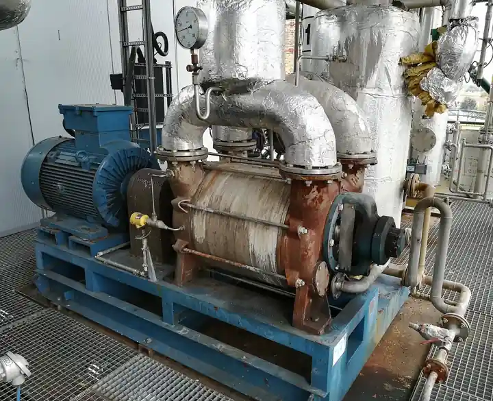
The air comes from real places: valve packing and flange leaks under vacuum, turbine gland seal imperfections, dissolved gases in makeup water that flash out of solution in the hotwell, and process in-leakage on direct-contact equipment. Design practice sizes air removal on 5 to 10 SCFM of dry air at the design vacuum for a power-size unit, with the actual in-leakage measured by the helium or tracer gas survey during commissioning. The classic removal machine is a two-stage steam jet ejector train with intercondensers, using 10 to 20 bar motive steam and no moving parts, the same physics as the standalone steam ejector leaf. The alternative is a liquid-ring vacuum pump, an electrically driven machine that seals with condensate, the architecture shown in the lead image; hybrid trains use one ejector stage for hogging down from atmosphere and the liquid ring for efficient steady holding duty.
Hogging and holding are different duties and the RFQ must state both. Hogging is the startup job: removing the roughly vessel-volume of air at atmospheric pressure down to the point where steam can establish vacuum, ideally in 20 to 45 minutes on a power unit. Holding is the continuous job at design vacuum against standing in-leakage. A train sized only for holding takes hours to pull the unit down; a train sized only for hogging wastes motive steam or motor power at steady state. Vendors quote both numbers, and the acceptance test for air removal is a performance curve, air removal capacity versus suction pressure, not a single point.
The vacuum envelope also loads the structure. At 5 kPa absolute the atmosphere pushes roughly 96 kPa, about 9.8 tonnes per square meter, onto the shell, so the vessel is designed as a vacuum vessel with stiffeners, and the flexible exhaust duct between turbine and condenser is designed for full vacuum collapse without crumpling. Waterbox covers carry the same external load plus circulating water pressure. The ASME Section VIII external-pressure rules and the turbine-generator foundation interface both appear in the design basis, and a condenser that passes the thermal guarantee but flexes the turbine foundation off alignment has failed anyway, which is why spring-supported, rigidly-supported, and foundation-mounted arrangements are an explicit purchase decision in chapter 3.
Condensate chemistry closes the loop. Oxygen in the hotwell comes from air in-leakage and from dissolved gases in the condensate itself; power practice targets 7 to 20 ppb dissolved oxygen in hotwell condensate, measured by the same dissolved oxygen meter technology used in boiler feed chemistry, and achieved by deaeration in the condenser neck, a trays-and-spray deaerating zone above the tube bundle, plus chemistry control in the cycle. A condensate polishing system or a full-flow polish is added when the boiler demands it, and a silica analyzer or a conductivity meter on the hotwell catch is often the first line of detection for a cooling water in-leak, because a single pinhole tube injects circulating water ions straight into the feed cycle.
Chapter 3 / 06
Types, Construction, and Duty Boundaries
Shell architecture splits into cylindrical and rectangular, and the split follows size and shipping. Cylindrical shells, built like large ASME vessels with internal tube bundles, dominate below roughly 100,000 lb/h of steam duty and process applications where shop fabrication and code stamping matter. Rectangular, or box, shells welded into the turbine house foundation dominate power-plant service because they wrap the tube bundles around the turbine exhaust duct footprint, admit steam across the entire top face, and ship in modules for field erection. Modular construction, in which the shell walls, tube bundles, waterboxes, and hotwell are match-marked shop modules assembled on site, is the norm for units above about 200 MW where a single shop-built vessel would exceed rail and road limits.
Bundle and waterbox arrangement defines the tube-side passes and maintenance access. Single-pass condensers, with cooling water flowing once through the bundle, suit once-through sites with cold sea or lake water and low temperature rise targets. Two-pass designs, water in and out on the same end, are the workhorse of cooling tower circuits because they double tube-side velocity per unit water flow. Divided waterbox designs split the circulating water into two independent halves so one half can be opened and cleaned while the unit runs at reduced load, a commercial decision worth real money on sites without cooling water filtration. Tube counts run from a few hundred on small process condensers to more than 40,000 on 1,000 MW-class nuclear low pressure service, with tube lengths of 6 to 18 m.
Once-through versus recirculating cooling water is the largest single design fork. Once-through sites draw ambient sea, lake, or river water, run it through the condenser, and return it, so design water temperature follows climate and the environmental permit, and fouling control targets debris, marine growth, and silt. Recirculating sites pair the condenser with a cooling tower or a dry cooler circuit, so design water temperature is the tower approach temperature above ambient wet bulb, typically 3 to 8 deg C warmer than a once-through site, and the condenser must reach its guarantee pressure at that warmer water. The choice moves design condenser pressure by whole kilopascals and must be frozen before the tube surface is optimized, because the same turbine guaranteed at 5 kPa on lake water cannot be guaranteed at 8 kPa on tower water without a different bundle.
Single- versus multi-pressure shells apply to multi-exhaust turbines. Where two or more low pressure turbine exhausts feed separate shell-side zones in one casing, each zone can run at its own pressure with its own water path in series, so the cold end of the water flow serves the zone that benefits most. Two-pressure condensers on combined cycle and supercritical coal units typically recover 0.1 to 0.3 percentage points of heat rate over an equivalent single-pressure design, at the cost of a partitioned shell and more complex waterbox routing. The purchase decision is economic: the multi-pressure premium pays back where water is warm and the unit runs at high load factor.
Tube materials follow water chemistry, and the choice is a table, not a preference. Admiralty brass (C44300) is the historical default for fresh circulating water, cheap and conductive but vulnerable to ammonia attack at air cooling zones and to sulfides. Stainless 304L and 316L tubes handle fresh water with higher chlorides and resist ammonia, but are sensitive to chloride stress corrosion above roughly 200 ppm chlorides at the temperatures involved. 90-10 copper nickel (C70600) and 70-30 copper nickel (C71500) are the sea water standards, with 70-30 or the 2-1 iron-modified grades reserved for sea water inlet ends and air removal zones. Titanium tolerates almost any water, including high chloride and polluted brackish service, at a thin wall and premium price; duplex stainless occupies the space between 316L and titanium. Tube wall gauges run 18 to 24 BWG by service, with thinner walls bought for heat transfer and thicker for erosion at inlet ends, where plastic or metal inserts extend inlet-end life in debris-laden water.
The duty boundaries deserve blunt statements. A surface condenser is not an evaporative condenser, which rejects refrigeration heat through wetted coils, and it is not a chiller, which moves heat with a vapor compression cycle rather than condensing turbine exhaust. Where site water is unavailable, the honest purchase is an air-cooled condenser arrangement, and the selection chapter treats that trade explicitly. Where the duty is small, a few hundred kilograms per hour of exhaust from a small back-pressure turbine, a compact spiral or shell-and-tube unit without an elaborate hotwell may serve. And where the real problem is steam conditioning rather than vacuum production, the steam separator or the desuperheater is the right page. The table below consolidates the boundaries.
Duty or site condition
Construction to specify
Boundary to respect
Utility power block, recirculating tower water
Rectangular modular shell, two-pass, divided waterbox, 304L or 316L tubes
Design pressure set by tower approach temperature, not ambient
Coastal station, once-through sea water
Single or two pass, 70-30 CuNi or titanium tubes, inlet-end inserts
Marine growth and silt controls; chlorination permit limits
Geothermal or biomass cycle, non-condensable rich steam
Oversized air cooling zone, dual-stage ejector or hybrid air removal
Gas loading can exceed power-plant sizing rules; purge NCG continuously
Captive process drive, 10 to 60 MW mechanical drive
Cylindrical shop-fabricated shell, single bundle, skid-mounted air removal
Hotwell storage sized for trip load and bypass dump
Arid site, no cooling water
Air-cooled condenser arrangement instead, or dry cooler hybrid
This water-cooled page does not cover ACC fan power economics
Combined cycle with two LP exhausts
Two-pressure shell with partitioned hotwell and series water path
Heat rate credit must justify partitioned casing complexity
Small exhaust duty under 1,000 lb/h
Compact shell-and-tube aftercondenser, no hotwell chemistry package
Beyond this scale a dedicated leaf or a process HX vendor quote is honest
Chapter 4 / 06
Key Specification Parameters
The datasheet rows below decide whether a quoted condenser matches the cycle. Each row is a purchase defining parameter; the paragraphs after the table explain what to demand and what a weak answer looks like.
Attribute
Typical range or options
What it decides
Exhaust steam flow
2,000 to 2,000,000 lb/h (0.25 to 250 kg/s)
Surface area, shell size, hotwell capacity, and guarantee basis
Design condenser pressure
0.5 to 4.0 in HgA (1.7 to 13.5 kPaA)
Turbine heat rate and the whole thermal guarantee
Cooling water flow
1,000 to 400,000 gpm (60 to 25,000 L/s)
Tube-side velocity, number of passes, and pump operating cost
Water inlet temperature, design
15 to 35 deg C once-through; wet bulb plus 3 to 8 deg C tower
Saturation floor under the condenser, pressure guarantee point
Cleanliness factor
0.85 typical guarantee; 0.70 to 0.90 range
Surface area margin against fouling between cleanings
Tube material and gauge
Admiralty, 304L, 316L, 90-10 and 70-30 CuNi, duplex, titanium; 18 to 24 BWG
Water chemistry survival, heat transfer, and erosion life
Tube-side velocity
1.8 to 2.4 m/s design band
Fouling control, inlet-end erosion, and circulating pump head
Air removal capacity
5 to 25 SCFM dry air at design vacuum; hogging 20 to 45 min
Vacuum holding under in-leakage and startup pull-down time
Hotwell dissolved oxygen
7 to 20 ppb with deaerating neck
Condensate chemistry acceptance by the feed system
Effective surface area
500 to 120,000 m2 total outside tube area
The physical size behind the guarantee, auditable at bid
Code and standards basis
current HEI edition, named in the RFQ; ASME Section VIII; TEMA where applicable
The rulebook the guarantee and the vessel stamp answer to
The pressure row is where bids are won and lost, and it must never be read alone. A quotation of 3.8 kPaA is meaningless until the water inlet temperature, water flow, cleanliness factor, and steam enthalpy behind it are on the same line. HEI practice, published by the Heat Exchange Institute in its Standards for Steam Surface Condensers, is the common rulebook: it fixes the reference heat transfer coefficients by tube size and material, defines cleanliness factor accounting, and sets air removal sizing conventions. A bid that guarantees a pressure at 0.95 cleanliness with a stated fouling allowance and a bid that quietly assumes 0.90 are not the same machine, and the performance test clause, usually an ASME PTC 12.2 based acceptance test, is what forces the difference into daylight.
Tube velocity is the quiet row that decides decade cost. Below about 1.5 m/s, fresh water fouling and slime deposition accelerate and surface performance decays between cleanings; above about 2.7 m/s, inlet-end erosion and vibration risk rise, particularly on soft brass alloys. The 1.8 to 2.4 m/s band is where fouling control and erosion life balance, and the number is set by tube count per pass, tube diameter, and water flow together, so an RFQ that fixes flow without fixing velocity target leaves the vendor free to optimize capital cost at the expense of the operating budget. The companion table converts water chemistry into tube material decisions a specifier can defend.
Circulating water condition
Tube material to specify
Watch items
Clean fresh water, closed loop tower
304L stainless
Chloride stress corrosion if cycles of concentration climb
Fresh water with ammonia carryover
316L or CuNi air zone, stainless main bundle
Air cooling zone ammonia concentration attack on brass
Brackish, 200 to 1,000 ppm chlorides
90-10 CuNi or duplex stainless
Seasonal salinity swings; inlet-end inserts for silt
Sea water, once-through
70-30 CuNi or titanium
Marine growth chlorination permit; erosion shields at inlet
Polluted or sulfide-bearing estuary water
Titanium thin wall
Premium justified by any alternative's failure history
High purity closed circuit, dry cooler loop
Admiralty or 304L with chemistry control
Corrosion is not the limit; freeze protection is
The instrumentation rows make the guarantee measurable. Shell pressure is read by an absolute pressure transmitter, not a gauge, because the numbers live below atmosphere; cooling water inlet and outlet temperatures are read by calibrated resistance elements, and the temperature transmitter or local indication behind them feeds the performance calculation, and a pressure transmitter on the circulating water inlet and outlet rounds out the set by confirming water side health between outages. Hotwell level by a level transmitter governs the condensate pump control loop. Dissolved oxygen and conductivity or silica monitoring on the hotwell catch provide the leak and chemistry tripwire, and a differential pressure reading across the circulating water side flags tube fouling between outages. A condenser quoted without instrument taps and test nozzles is a condenser that cannot be acceptance tested, and an untestable guarantee is marketing.
Chapter 5 / 06
Selection Decision Factors and RFQ Language
The decision sequence runs as a checklist, and each step eliminates a class of bids before price comparison begins.
Fix the cycle basis first: exhaust steam flow and enthalpy at the guarantee load, plus the bypass dump flow the condenser must swallow at turbine trip.
Fix the water basis: source, design inlet temperature at the guarantee point, available flow, and whether the circuit is once-through or tower recirculating, because design pressure follows from this more than from any hardware choice.
State the target condenser pressure as an economic choice, using the turbine heat rate sensitivity the OEM publishes, typically 0.7 to 1.0 percent output per kPa, and buy surface down to the point where the next square meter stops paying.
Set the cleanliness factor and fouling allowance in the guarantee table, 0.85 is customary, with the water chemistry history of the site in writing so the vendor owns the fouling risk it prices.
Choose tube material from the chemistry table in chapter 4, name gauge and length, and state the design velocity band.
Specify the air removal package explicitly: hogging time from atmosphere, holding capacity in SCFM of dry air at design vacuum, and the utility, motive steam or electric, that powers it.
Define the hotwell: capacity in minutes at full load, deaeration target in ppb dissolved oxygen, and the storage volume the trip case demands.
Fix the verification basis: HEI edition as the design reference, ASME PTC 12.2 based acceptance test, and the correction curves, water temperature and flow deviations, that the guarantee table carries.
Against neighboring heat rejection equipment, the comparison a specifier actually runs is the following, and it belongs in this selection chapter rather than in the page title. Against an evaporative condenser, the machines do different jobs: that device condenses refrigerant in a vapor compression cycle with evaporative water cooling, while the surface condenser condenses steam and recovers condensate; a refrigeration plant buying heat rejection belongs on that page, and a steam cycle belongs here. Against air-cooled heat exchanger and dry cooler arrangements, water-cooled vacuum wins 3 to 6 kPa of back pressure in hot climates at the cost of water consumption and its permitting; arid sites pay the fan power and take the higher design pressure, and combined hybrids split the duty. Against a cooling tower circuit, the tower sets the design water temperature this page consumes, so the two purchases are sequential, not alternatives. Within the machine itself, the ejector versus liquid-ring vacuum pump choice trades motive steam simplicity against electric efficiency, and the divided waterbox versus single waterbox choice trades capital against the ability to clean at load.
The application map below turns those choices into a table the project file can carry into bid evaluation.
Application
Construction to specify
Check before order
Combined cycle HRSG plant, tower water
Rectangular two-pressure shell, 304L tubes, hybrid air removal
Two-pressure heat rate credit against casing premium; bypass dump sizing
Coastal once-through utility unit
Divided waterbox, 70-30 CuNi or titanium, inlet inserts
Chlorination permit; debris loading and travel screens
Ash-laden air in-leakage; quarterly online cleaning window
The RFQ block should be written once and reused. A complete block reads: exhaust steam flow at guarantee load with enthalpy; bypass dump flow and enthalpy; design condenser pressure in kPaA or in HgA; cooling water source, design inlet temperature, flow, and maximum outlet temperature; cleanliness factor and fouling allowance; tube material, gauge, diameter, length, and design velocity; shell arrangement, cylindrical or rectangular, and support interface; number of tube passes and divided waterbox requirement; air removal type, hogging time, holding SCFM at design vacuum; hotwell capacity in minutes and dissolved oxygen target with deaerating neck; instrumentation list with absolute pressure transmitter, temperature transmitter at water inlet and outlet, and level transmitter; materials for shell, tubesheets, and waterboxes against the water analysis; design codes, HEI edition, ASME Section VIII for the shell, and the nozzle loads the connecting piping may apply; site logistics limits that force modular shipment; and the acceptance test basis with correction curves. A quotation returned without the guarantee table, or with a pressure quoted at unstated water conditions, is incomplete at any price.
Chapter 6 / 06
Installation, Standards, Failure Modes, and Maintenance
Installation is a structural event as much as a piping one. The condenser anchors the bottom of the steam cycle: on power units it is either foundation-mounted under the turbine, spring-supported with load transferred to the turbine deck at vacuum, or rigidly bolted with an expansion joint in the exhaust duct, and the choice fixes how turbine alignment moves when the shell draws vacuum and its stiffness changes. Circulating water piping imposes nozzle loads the shell design must bound, and the expansion provisions on both water and steam sides belong in the design review, not the field change log. Before first vacuum, the shell is soap-tested and the whole condensate side is helium leak checked, because a weld pore that is invisible at atmosphere becomes an air leak that the air removal package chases forever.
Commissioning protects the guarantee. The initial pull-down is the air removal package's first acceptance event, and hogging time from atmospheric to the point where steam sustains vacuum is logged. In-leakage is then surveyed, helium or sulfur hexafluoride tracer at every flange, valve packing, and gland under vacuum, with the standing rule that measured in-leakage above roughly 1 SCFM per 100 MW points at a repair list, not at a bigger vacuum pump. The thermal acceptance test then runs at specified water flow and temperature bands, reads absolute pressure, water temperatures, and steam flow, and applies the correction curves from the guarantee table. Condensate chemistry is verified at the same time: hotwell dissolved oxygen against the ppb target and a conductivity or silica baseline that will later serve as the leak tripwire.
The standards frame is short and non-negotiable. The Heat Exchange Institute Standard for Steam Surface Condensers fixes reference coefficients, cleanliness accounting, air removal conventions, and test tolerances; bids should name the edition. The shell and, where applicable, the waterboxes are designed to ASME Section VIII, with external pressure design for full vacuum; TEMA construction practice applies where the procurement blends process exchanger practice. The acceptance test follows ASME PTC 12.2 or the contract's equivalent. Cooling water chemistry limits, chlorination for marine control and inhibitors for closed loops, follow the site water treatment program, and the environmental permit governs once-through discharge and biocide use on once-through and tower circuits alike.
Failure modes follow a predictable list. Tube fouling and scaling raise back pressure season by season; the symptoms are a creeping condenser pressure at constant load and a rising temperature difference across the shell, and the remedies are online ball or brush cleaning systems, chemical descaling at outage, or a divided waterbox design that lets half the bundle be cleaned at load. Tube leaks are the acute failure: a single leaking tube injects circulating water into the feed cycle, conductivity and silica in the hotwell spike, and the unit derates while the leak is located by tube sampling and plugged; a leak history beyond a few percent of plugged tubes per year is an economics case for retubing with a better alloy. Air in-leakage starves vacuum gradually; the air removal package runs hot, the air cooling zone blankets tubes, and dissolved oxygen in the hotwell climbs, all three pointing back at flanges and glands rather than at the condenser itself. Steam-side erosion at the bypass dump zone and flow-accelerated corrosion at wet steam impingement points are mechanical wear items with named repair weld overlays. Waterbox and tube-side corrosion track water chemistry, and inlet-end erosion tracks velocity and debris.
Maintenance economics scale with the water side. A once-through sea water station plans annual or semiannual in-service cleaning windows and treats tube integrity testing, eddy current survey on a rolling fraction of the bundle, as a scheduled scope item; the eddy current trend decides retubing before leaks decide it. Fresh water tower circuits stretch cleaning to multi-year intervals but monitor cycles of concentration and chemistry continuously. Instrument calibration, the absolute pressure transmitter above all, is annual, because a drift of 0.3 kPa in the pressure reading quietly misprices every performance calculation built on it. None of these scopes costs what one summer of 1 kPa excess back pressure costs on a power unit, and every one of them produces a number the next RFQ can use, which is how a purchasing file gets smarter instead of just older.
FAQ
What condenser pressure should a new surface condenser guarantee?
Design pressure follows the water, not ambition: fix the design cooling water inlet temperature and flow first, then target a terminal temperature difference of 2.8 to 5.6 deg C above the water outlet temperature. Once-through lake or sea water sites typically land near 3.5 to 5 kPaA, while cooling tower circuits land 1.5 to 3 kPa warmer in pressure terms. Buy surface area until the next square meter stops paying for itself in turbine output, using the OEM heat rate sensitivity of roughly 0.7 to 1.0 percent output per kPa.
How much cooling water does a steam surface condenser need?
The rule of thumb is 60 to 100 times the steam mass flow by mass, aiming for a circulating water temperature rise of 8 to 12 deg C across the shell. Lower flow saves pump capital and power but raises outlet temperature, terminal temperature difference, and back pressure; higher flow flattens the rise but pushes tube velocity toward erosion limits. The optimum is set jointly with tube count and pass arrangement so design velocity stays in the 1.8 to 2.4 m/s band.
Which tube material survives my cooling water?
Match the alloy to the water analysis. Clean fresh closed loops take 304L stainless; ammonia-bearing cycles move the air cooling zone to CuNi or stainless; brackish water takes 90-10 CuNi or duplex; full sea water takes 70-30 CuNi or titanium, with titanium the default where sulfides or pollution rule out copper alloys. Wall gauge and inlet-end inserts then tune erosion life against heat transfer, and the whole choice is written into the guarantee table as a fouling and corrosion allowance.
Should air removal be a steam ejector or a liquid-ring vacuum pump?
Ejector trains are simple, motive-steam driven with no moving parts, and tolerate wet conditions; they suit sites with cheap steam and modest holding loads. Liquid-ring vacuum pumps cost more up front but hold vacuum far more efficiently at steady state, typically cutting continuous energy use on power-size units; hybrid trains use one ejector stage to hog down from atmosphere and the liquid ring to hold. Specify both hogging time from atmosphere and holding capacity in SCFM of dry air at design vacuum, whichever machine you buy.
What does HEI actually govern in a surface condenser purchase?
The Heat Exchange Institute Standard for Steam Surface Condensers is the industry rulebook: it publishes reference heat transfer coefficients by tube material and size, defines cleanliness factor accounting, sets air removal sizing conventions, and frames the acceptance basis. Naming the edition in the RFQ forces every bid onto one comparison basis, so a 3.8 kPaA quote at 0.90 cleanliness and a 4.2 kPaA quote at 0.85 cleanliness can be read for what they are rather than compared as raw numbers.
Why is hotwell dissolved oxygen a condenser specification item?
Because the hotwell is the first catch basin of the feed cycle. Air in-leakage and dissolved gases in condensate show up as oxygen in the hotwell, and power practice targets 7 to 20 ppb to protect the condensate system and boiler from corrosion. The condenser achieves it with a deaerating neck, spray and tray zones that strip gases before the condensate reaches storage, and the air removal package that keeps shell gas loading low. A dissolved oxygen meter on the hotwell catch is both the compliance instrument and the earliest air-leak alarm.
Is a surface condenser the same equipment as an evaporative condenser?
No, and confusing the two buys the wrong machine. A surface condenser condenses turbine exhaust steam on the outside of water-cooled tubes, creates process vacuum, and returns clean condensate to the boiler cycle. An evaporative condenser condenses refrigerant inside coils while water sprays evaporate off the coil surfaces, serving vapor compression refrigeration plants. If the duty is steam cycle vacuum, buy this page; if the duty is refrigeration heat rejection in a water-frugal site, the evaporative machine is the correct purchase.