A deaerator is a pressure vessel in the boiler house that heats feedwater to the saturation temperature of the steam it contacts, spraying and cascading the water through trays or packing so that dissolved gases, mainly oxygen and carbon dioxide, are driven out of solution and vented to atmosphere. The vessel also stores a measured inventory of hot deaerated water, typically five to ten minutes of full boiler load, and mounts high enough above the boiler feed pump suctions to provide the net positive suction head the pumps need on water already at or near saturation. Pressurized spray and tray deaerators hold the water at 0.2 to 3 bar g of steam pressure and deliver residual dissolved oxygen below 7 parts per billion in normal service, while atmospheric feedtank versions with deaerator heads run warmer than ambient but deliver oxygen levels that still require chemical scavenging downstream.
Procurement engineers meet these vessels wherever boiler pressure and duty make oxygen pitting an economic risk: process steam plants in pulp and paper, chemical and food processing, hospital and campus steam systems, and power boiler feed trains. The decision this page settles is what the vessel must be specified to deliver on paper: the residual oxygen target, the storage minutes and NPSH margin at the feed pump suction, the venting arrangement, and the instrumentation that proves the deaeration is actually working. The answer lands as an RFQ line set covering steaming rate, condensate and makeup fractions, design pressure, storage volume, materials, and code stamp, and every chapter below feeds that line set so the boiler is protected by calculation rather than by hope.
This page treats the deaerator as a purchasing object: what spray and tray sections actually remove and to what number, how storage volume converts into NPSH at the boiler feed pump, what the vent orifice and instrumentation prove, and how steaming rate, materials, and code stamp combine into a defensible RFQ. It is written for engineers who issue purchase specifications, not for readers who want a brochure summary.
Chapter 1 / 06
What a Deaerator Is and What Is Being Decided
The physics is Henry's law applied as equipment. The amount of a gas that stays dissolved in water falls as the water temperature rises toward saturation and as the partial pressure of that gas above the water falls. A deaerator exploits both levers at once: steam heats the incoming feedwater to within a fraction of saturation, and the design spreads the water into films and droplets with enormous surface area while stripping steam flows counter to it, so oxygen and carbon dioxide leave the water and ride the vent steam out. The vessel is therefore two machines in one shell, a mass transfer stage that removes gases and a storage stage that buffers the boiler between load swings, and both stages must be specified separately because they fail separately.
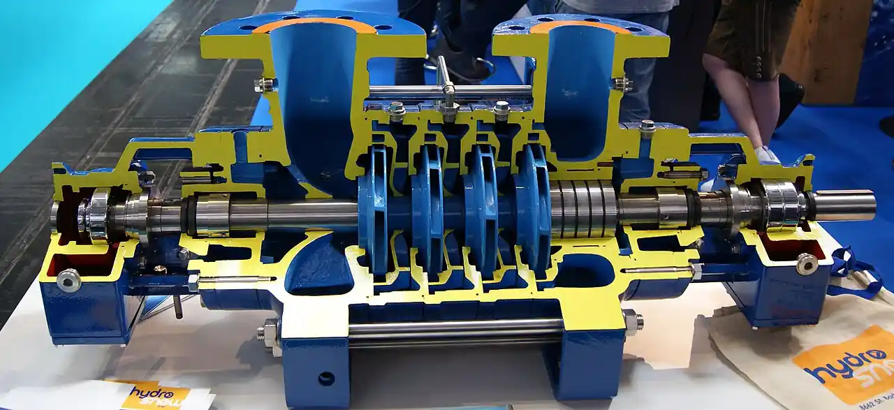
What is actually being decided in this purchase is three guarantees. First, chemistry: the vessel must deliver feedwater with residual dissolved oxygen low enough that the remaining oxygen, together with a chemical scavenger polish, cannot pit the boiler drums and tubes; pressurized deaerators guarantee levels below 7 parts per billion, and the best spray-tray designs guarantee down to 5. Second, hydraulics: the storage section must hold enough hot water, at enough elevation above the pump suction nozzles, that the boiler feed pump never cavitates, and the available NPSH calculation belongs in the deaerator datasheet because it is the vessel that provides it. Third, mechanical integrity: the vessel is a code-stamped pressure vessel full of oxygen scavenger chemistry and hot condensate, and its materials, weld examination, and relief protection are bought once and lived with for decades. The feed pump downstream is usually a multistage pump, a centrifugal pump with impellers stacked in series for the high differential the boiler demands, and it is the least forgiving consumer of the vessel's storage design.
Against its neighbors the deaerator occupies deliberate ground. A steam separator dries flowing steam by knocking droplets out of the vapor, the mirror image problem, and neither substitutes for the other. A condensate return pump or its receiver collects condensate from low points and delivers it to the feedtank, which is often the deaerator itself in small plants. A steam ejector can pull vacuum on processes but appears in the boiler house only in special vacuum deaeration duty. The boiler feed pump takes the deaerator's water onward, and a condensate pot serves impulse lines on the measurement around the vessel, not the feedwater itself. The deaerator takes the narrow territory where feedwater chemistry and feed pump suction conditions are both set by one vessel, and no neighbor covers both.
Four references organize the datasheet. ASME Boiler and Pressure Vessel Code Section VIII Division 1 stamps the pressurized shell, and its Appendix where applicable addresses the inspection regime. The Heat Exchange Institute standards for deaerators carry the performance rating basis, including the accepted residual oxygen test method at rated conditions. ASME PTC 12.3 context covers feedwater heater acceptance testing where the deaerator is treated as a heater stage, and water chemistry limits come from the ABMA boiler water guidelines that the oxygen guarantee must be read against. A datasheet that quotes none of these is a price tag, not a specification, and a residual oxygen guarantee without a stated test method and load condition cannot be enforced.
The RFQ should also name the neighbors so the train checks out as a system. Condensate returns from the steam distribution system through steam traps and a receiver or direct to the deaerator inlet; makeup water arrives from the water treatment plant with its own hardness analyzer and silica analyzer readings already in the log; flash steam and vent losses are accounted against the steam balance. Downstream, the boiler feed pump set with its check valve and recirculation protection lifts from the storage section, a pressure reducing valve on auxiliary steam pegs the deaerator when turbine extraction is unavailable, and a safety relief valve on the shell protects the storage section against overpressure from the steam side. Instrumentation around the vessel, a level transmitter on the storage section, a pressure transmitter and temperature transmitter on the dome, and a conductivity meter or dissolved oxygen meter on the outlet, is what turns the guarantee into a monitored number. Stating the whole train in the RFQ lets one supplier check nozzle loads, elevations, and chemistry compatibility in a single pass.
Chapter 2 / 06
How Spray and Tray Sections Strip Dissolved Gases
The mass transfer happens in two stages arranged in series, and the split explains most datasheet differences. In the first stage, incoming cold feedwater, typically 70 to 105 deg C after condensate mixing, is sprayed through spring-loaded spray valves into a steam atmosphere in the dome. Heating to saturation within the spray cone removes the majority of the dissolved oxygen, commonly 90 percent or more of the inlet load, because droplet surface area is highest exactly when the water is furthest from equilibrium. In the second stage, the water cascades downward over a stack of trays or structured packing while fresh stripping steam, admitted at the bottom of the section, flows upward counter to it; the water arrives already near saturation and gives up its remaining gases to the steam, which condenses in turn and adds its latent heat to the water it leaves behind. The vent at the top carries the stripped oxygen, carbon dioxide, and a small designed fraction of steam to atmosphere or a vent condenser.
The venting discipline is what separates a working deaerator from a warm tank. The gases released in the sections must be pushed out by a continuous flow of steam through the vent, and the vent line carries a restriction or orifice sized to hold a measurable steam discharge, commonly a fraction of one percent of the steaming rate. An undersized or blocked vent re-accumulates the stripped gases in the dome, raises their partial pressure, and the dissolved oxygen in the outlet climbs while every other parameter reads normal. Operating procedures therefore treat the vent as a live indicator: a warm plume means the deaerator is breathing, and commissioning includes verifying the vent steam flow against the design figure. A vacuum or sub-atmospheric variant exists for low temperature duty, but the industrial boiler house standard is the pressurized spray-tray machine precisely because the vent can be seen and audited.
Storage and NPSH convert the vessel into pump protection. Below the deaeration section sits the storage section, sized in minutes of boiler steaming at full load, commonly 5 minutes for base load plants, 10 for systems with violent load swings or slow condensate returns. The stored water is at saturation, the least forgiving suction condition a pump can face, because any pressure drop in the suction line flashes it to steam. Available NPSH is therefore built from elevation alone: the height of the water surface above the pump suction nozzle centerline, minus friction and the vapor pressure head, and deaerator installations stand on legs or a platform at 6 to 10 meters precisely to generate the 3 to 6 meters of NPSH margin that multistage boiler feed pumps demand. The pump datasheet and the vessel datasheet must be read together, because a supplier who quotes the vessel without the pump suction datum has not checked the second guarantee.
Chemistry closes the loop. Even a healthy pressurized deaerator leaves a few parts per billion of oxygen and some carbon dioxide, so boiler water treatment adds a scavenger, sodium sulfite below about 60 bar and hydrazine chemistry or its modern substitutes above, dosed into the storage section or the suction line. The scavenger does not replace the deaerator, because treating the full inlet oxygen load chemically costs reagent and produces dissolved solids; the vessel removes the bulk, the chemical polishes the remainder. Carbon dioxide that passes through as carbonic acid is neutralized by amine treatment in the distribution system, and the feedwater pH, tracked by a conductivity meter and a pH measurement on the outlet, is the number that shows whether the combination is working. A worked example fixes the arithmetic: a 20 tonne per hour boiler with 80 percent condensate return receives about 4 tonnes per hour of makeup saturated with air at 8 to 10 parts per million of oxygen; the deaeration section removes roughly 99.95 percent of it, and the outlet dissolved oxygen meter reads single digit parts per billion.
The performance map follows from the mechanism. At full steaming rate with hot condensate, spray-tray machines hit their guarantee, below 7 parts per billion, with margin. At deep turndown the spray valves may not fully atomize cold makeup, and transient oxygen excursions to a few tens of parts per billion appear until the section re-warms; the specification handles this by stating the guarantee at defined load points rather than everywhere. On startup with cold water the deaerator is simply a heater until it reaches pressure, and the scavenger dose carries the duty in between. Buyers who read these behaviors as defects have usually been quoted a guarantee curve that never existed; asking for the oxygen guarantee versus load and inlet temperature curve in the RFQ prevents the misunderstanding before contract.
Chapter 3 / 06
Types, Construction, and Duty Boundaries
Three architectures cover the catalogs. The spray-tray deaerator, the industrial standard, sprays inlet water into the dome and cascades it over tray stacks in a vertical or horizontal pressure vessel, with a separate storage section below or bolted alongside; horizontal shelf-type units dominate above roughly 20 tonnes per hour because the tray area scales with length. The spray-only deaerator relies on the dome stage alone, cheaper and shorter, and holds oxygen levels suitable for lower pressure boilers where the scavenger polishes a larger residual. The atmospheric feedtank with a deaerator head is the small plant answer: an open or lightly vented hot well at 85 to 95 deg C, fitted with a flash condensing head that recovers flash steam from returning condensate and strips part of the gases, delivering water that still carries 40 parts per billion or more of oxygen and depends on sulfite treatment for the rest. Within each architecture the buyer still chooses storage arrangement, materials, and steam supply, and those choices carry more warranty weight than the architecture name.
Storage arrangement sets the plant layout. The integrated design puts the storage section directly under the deaeration dome in one shell, compact and common to the middle sizes. The two-vessel design separates a vertical dome from a horizontal storage tank, each with its own code stamp, favored on large plants where the storage tank doubles as the suction manifold for multiple feed pumps. The kettle or direct contact design heats and stores in one body without trays, essentially a feedtank under pressure, and appears where condensate returns are hot and makeup is small. Whatever the arrangement, the elevation drawing that locates the storage waterline above the boiler feed pump nozzle is part of the purchased scope, not an afterthought left to the piping designer.
Materials follow the chemistry. Shells are carbon steel SA-516-70 as the norm, with stainless clad or 304L and 316L internals where the condensate chemistry, high chlorides, or carbonic acid aggression justifies them; tray stacks are 304 or 316 stainless sheet in both cases because the trays live in the wet steam transition zone where plain carbon corrodes. Spray valves are stainless with hardened seats, and the vent condenser, where fitted, is stainless or copper alloy tube. Vacuum deaerators for low temperature duty add larger gas removal equipment and appear mostly in water treatment rather than boiler service. The premium for full stainless internals on a mid-size unit runs in the tens of percent range, and it buys decades of tray integrity on plants whose condensate carries carbon dioxide; on plain softened makeup with good amine control, carbon steel trays have also served long lives, so the choice is chemistry driven rather than universal.
Boundaries are worth stating bluntly. A deaerator is not a feedwater heater in the power plant sense, because it heats to saturation by direct contact rather than in closed tube bundles, and it is not a boiler feed pump protector alone, because the chemistry duty stands on its own. It does not replace water treatment upstream: hardness and silica in the makeup must still be removed by softening and demineralization before the water reaches the vessel, or the deaerator becomes an expensive scale accumulator. And on small low pressure systems, an atmospheric feedtank with honest sulfite dosing may be the economic answer, because a pressurized vessel bought only for its oxygen guarantee, then run cold and unvented, delivers neither. The duty map below pairs the common stations with the construction that survives them.
Station
Suitable construction
Construction to avoid
Process boiler 10 to 60 bar, high condensate return
Spray-tray, horizontal, 5 min storage, SS trays
Spray-only unit at high makeup fraction
Power boiler with extraction steam
Two-vessel, tray, pegging PRV on auxiliary steam
Single shell with undersized storage for swing duty
Hospital or campus steam, variable load
Vertical spray-tray, 10 min storage, fast level control
Tight storage sized only for base load
Small firetube boiler below 10 bar
Atmospheric feedtank with deaerator head plus sulfite
Pressurized vessel run cold and unvented
High chloride condensate, coastal plant
316L internals and vent condenser
Bare 304 trays in aggressive carbonic condensate
Flash steam recovery from return lines
Feedtank head with flash condensing section
Open vent dumping flash steam to roof
Feed pumps far below the vessel
Storage elevation checked against NPSH curve
Elevation decided after pump purchase
Chapter 4 / 06
Key Specification Parameters
The table below decodes the datasheet lines that decide whether a quoted deaerator matches the boiler house. Each row is a purchase defining parameter; the paragraphs after the table explain what to demand and what a weak answer looks like.
Attribute
Typical range or options
What it decides
Steaming rate capacity
1 to 300 tonnes per hour family by size
Match to boiler evaporation and margin for peaks
Residual dissolved oxygen
Below 7 ppb pressurized; 5 ppb best spray-tray
The chemistry guarantee, tied to a stated test method
Whether the boiler feed pump cavitates on saturation water
Materials
SA-516-70 shell; 304 or 316 trays and spray valves
Tray life in carbonic or chloride condensate
Vent arrangement
Orifice sized for design steam flow, optional condenser
Gas removal discipline and heat loss accounting
Instrumentation
Level, pressure, temperature, outlet DO or conductivity
Turning guarantees into monitored operating numbers
Steam supply and pegging
Extraction or PRV station, pegging PRV for low load
Deaeration pressure held across the load range
The oxygen row deserves a paragraph of its own because it is the row most often waved at. A guarantee of below 7 parts per billion means nothing until the test method, load point, and inlet temperature are named with it; the honest datasheet states the HEI test basis and shows the guarantee across the load range, and the honest supplier accepts a performance test at commissioning with a calibrated dissolved oxygen meter on the outlet. Demand the curve, not the point. The same discipline applies to the storage row: minutes of storage are meaningless unless the flow basis is full boiler steaming, and a vessel quoted with 10 minutes at average load holds barely 6 at peaks.
The NPSH row is the one that crosses datasheets. The deaerator provides available NPSH as pure elevation minus losses, while the boiler feed pump datasheet states required NPSH with its margin; the RFQ should force the two numbers into one document by requiring the supplier to state the minimum waterline elevation for the stated pump inlet condition. The comparison table below compresses the guarantee checks into the form a specification meeting can argue from.
Evidence demanded
Strong answer
Weak answer
Oxygen guarantee
7 ppb at stated load and temperature, HEI method
Removes oxygen without a number or method
Turndown behavior
Oxygen versus load curve, startup excursions stated
Single point guarantee silently applied everywhere
NPSH provision
Minimum waterline elevation stated for the pump datum
Elevation left to the piping designer after order
Code evidence
ASME VIII stamp with U-1A and weld examination map
Built to code without stamp or papers
Storage basis
Minutes at full steaming rate, level control range stated
Large tank claim with no flow basis
Commissioning test
Outlet DO measured at load with calibrated meter
Visual check of a vent plume and sign-off
The steam supply row closes the specification. Most plants feed the deaerator from turbine extraction or a pressure reducing valve station off the main header, and the specification must state the minimum steam pressure the vessel may assume at full load, because the deaeration pressure, not the boiler pressure, sets the storage temperature and with it the entire NPSH arithmetic. A pegging PRV that holds dome pressure at low extraction load is standard on extraction plants, and its setpoint belongs in the control narrative. The quotation that quotes the vessel and leaves steam supply, vent routing, and instrumentation as site exercises is not a complete quotation.
Chapter 5 / 06
Selection Decision Factors and RFQ Language
The decision sequence is short enough to run as a checklist in a specification meeting, and each step eliminates a class of quotations before price comparisons begin.
Fix the boiler duty first: maximum steaming rate, operating pressure band, and the condensate return fraction, because the makeup fraction decides how much oxygen the vessel must actually remove.
Set the residual oxygen target against the boiler pressure class: below 7 parts per billion for pressurized plants, sulfite polish for the remainder, and an honest feedtank answer for small low pressure systems.
Size storage against the load behavior: 5 minutes for steady process duty, 10 for swinging campus or batch loads, with the level control range stated so the pump never sees the low level trip.
Compute the NPSH budget with the boiler feed pump datasheet on the same table, and buy the elevation drawing as part of the vessel scope.
Choose the architecture: spray-tray for makeup-rich or high pressure duty, spray-only for intermediate, atmospheric head for the small plant where sulfite carries the polish.
Fix materials from the condensate chemistry: carbon shell with stainless internals as default, 316L trays where chlorides or carbonic aggression are documented.
Specify the vent with a number: design steam flow, orifice sizing basis, and whether a vent condenser recovers the heat.
Fix the evidence set: ASME VIII stamp and papers, HEI basis oxygen guarantee with load curve, NPSH provision statement, and a commissioning dissolved oxygen test with a calibrated meter.
Against neighboring equipment, the comparison a specifier actually needs runs as follows, and it belongs here in the selection chapter rather than in the page title. A plain feedwater heater raises temperature in closed bundles without deaeration and appears on power plants alongside, not instead. A steam separator protects equipment from wet steam and removes nothing from feedwater. A vacuum deaerator reaches low oxygen at low temperature for injection water and boiler feed in specific duties, but adds gas removal machinery the boiler house does not need when it has steam to spare. The pressurized spray-tray deaerator wins when the plant has steam, a real boiler to protect, and a feed pump that needs suction head, which is the standard industrial case. Choose the machine the chemistry and the hydraulics demand, not the vessel a package supplier has on the floor.
The application map below turns that comparison into a table the project file can carry.
Application
Construction to specify
Check before order
Pulp and paper process boiler, 70 percent returns
Horizontal spray-tray, 10 min storage, DO meter
Oxygen curve at the makeup surge condition
Chemical plant 40 bar package boiler
Vertical spray-tray, 5 min storage, SS internals
Extraction steam availability at low load
District energy campus, violent swings
Two-vessel, oversized storage, fast level control
Level control tuning against the pump low level trip
Food plant with clean steam, 10 bar
Spray-tray with 316 contact parts, vent condenser
Materials letter for product-contact classification
Retrofit onto existing feedtank
Deaerator head on the tank, flash recovery
Tank rating and vent capacity for steam duty
Power boiler with cold startup duty
Tray unit with pegging PRV and startup vent plan
Startup oxygen excursions agreed with chemistry
The RFQ block should be written once and reused. A complete block reads: steaming rate at maximum boiler load with unit basis; condensate return fraction and makeup temperature range; residual dissolved oxygen target with test method and load points; deaeration design pressure and temperature with steam supply arrangement, extraction or PRV station, and minimum assured steam pressure; storage volume in minutes at full steaming with the normal control band; available NPSH provided at the stated boiler feed pump datum, with the elevation drawing in scope; shell and internals materials with stainless grade for trays and spray valves; vent sizing basis and optional vent condenser; instrumentation set, level transmitter with control valve, pressure transmitter, temperature transmitter, outlet dissolved oxygen meter or conductivity meter, and alarm levels; code stamp and inspection regime, ASME VIII with U-1A, or the EN 13445 equivalent where the plant governs; and the performance test at commissioning, outlet oxygen measured at two load points with a calibrated instrument. A quotation returned without the oxygen curve, the NPSH statement, or the stamp papers is incomplete at any price.
Chapter 6 / 06
Installation, Standards, Failure Modes, and Maintenance
Installation quality decides whether the vessel delivers both guarantees. Set the storage waterline elevation from the NPSH calculation before the structural drawings start, because retrofitting height after the platform is poured is the most expensive way to cure feed pump cavitation. Pipe the condensate and makeup inlets as the manufacturer directs, keep the spray valves accessible through the dome manway, and route the vent to a safe discharge with the orifice installed and tagged, never left on a shelf. The suction lines to the feed pumps run short, large, and without high spots, and each pump inlet keeps its own full-size drop from the storage section so one pump outage never introduces a vapor pocket shared with its twin. Support the vessel per the seismic and wind code that governs the site, and keep the relief valve on the shell or dome per the code stamp documentation, because the storage section can be overpressurized from the steam side under control failure.
Commissioning practice proves the chemistry, not just the mechanics. Bring the vessel to design pressure with steam and verify the vent flow against the design figure before admitting makeup at rate; then, at two load points, measure outlet dissolved oxygen with a calibrated meter and record the numbers as the guarantee evidence. Log the storage temperature against saturation for the dome pressure, a check that the thermometer and pressure transmitter agree, since a saturated water temperature reading below the pressure's saturation point means the water has not finished heating. Verify level control action through a full cycle, fill to high level and draw to the pump trip, and record the control valve response; on swinging loads this test, more than any datasheet number, is what prevents nuisance trips. Confirm the scavenger dosing arrangement, injection point and mix, so chemistry covers the startup transients the vessel cannot.
The standards set the verification frame. ASME Section VIII Division 1 stamps the pressurized shell and sets the relief protection context; the Heat Exchange Institute deaerator standards fix the performance rating and residual oxygen test basis; ASME PTC 12.3 context covers acceptance testing where the vessel is treated in the heater family; ABMA guidance frames the feedwater chemistry the guarantee feeds into. Where the plant sits under EN jurisdiction, the EN 13445 pressure vessel code and its national registration replace the ASME stamp, and the PED category follows the stored energy. A specification that cites the code and the test basis by name transfers the burden of proof to the supplier, which is where it belongs.
Failure modes in service follow a short and predictable list. Oxygen excursions with normal readings elsewhere: the vent orifice is blocked or the dome pressure control is holding the vessel below design temperature, and the outlet meter catches it; the fix is vent and pressure discipline, not more scavenger. Tray damage and collapse: water hammer from startup practices, condensate admitted to a hot dome through submerged inlets, or simple corrosion thinning of tray sheets; symptoms are rising outlet oxygen at load and debris at the pump suction strainer, and the repair is tray stack renewal through the manway. Spray valve wear: erosion from aggressive water raises the minimum atomizing flow and oxygen climbs at turndown, caught by the load curve test at the annual outage. Storage level control failure: a sticking level valve or misconfigured transmitter either starves the pumps, cavitation and trip, or floods the dome into the vent; both are procedure and instrument maintenance items. Shell corrosion under insulation at the operating band: the classic external attack on any hot vessel, found by inspection regime rather than instrumentation, and reason enough to specify insulation inspection ports. Long term internals thinning where carbon steel trays were chosen against aggressive condensate chemistry: the annual oxygen trend drifts up years before failure, which is the argument for the stainless internals premium on chemistry that warrants it.
Maintenance intervals scale with duty severity. A steady process deaerator deserves an annual outage with vent orifice verification, spray valve inspection through the manway, tray stack visual and thickness checks, and a two point dissolved oxygen test at reload. Swinging duty or aggressive condensate moves tray and valve inspection to every second or third year at most, with the outlet oxygen trend reviewed monthly between outages. The instrumentation set, level, pressure, temperature, and oxygen or conductivity, is calibrated on the site instrument schedule, and every reading logged against load builds the trend file that makes the next RFQ smarter. None of these checks costs a tenth of one boiler tube failure from oxygen pitting, and every one of them produces a number the next purchase can use, which is how a purchasing file gets smarter instead of just older.
FAQ
What residual dissolved oxygen should a deaerator deliver?
Pressurized spray and tray deaerators are specified to deliver below 7 parts per billion at stated load and inlet temperature, with the best designs guaranteeing down to 5. Atmospheric feedtank versions with deaerator heads deliver on the order of 40 parts per billion or more and rely on sulfite scavenging downstream. Always demand the test method and the load points behind the number, because a guarantee without them cannot be enforced at commissioning.
Spray only or spray and tray, which should I buy?
Spray and tray is the default for makeup-rich plants and higher pressure boilers, because the tray stage polishes the last oxygen after the spray stage does the bulk of the heating work. Spray only suits intermediate duties with hot condensate and small makeup fractions at lower cost and height. If the makeup fraction is large or the boiler runs above about 20 bar, buy the trays; the scavenger bill and pitting risk of a marginal spray unit outrun its price advantage quickly.
How much storage capacity does the vessel need?
Common practice is 5 minutes of full boiler steaming rate for steady process load and up to 10 minutes for swinging campus or batch duty with slow condensate returns. The basis must be full steaming rate, not average, and the normal level control band plus the pump low level trip should be stated so the usable volume is explicit. Undersized storage shows up as feed pump trips during load transients, not as chemistry problems.
Why does NPSH decide the vessel elevation?
The stored water is at saturation, the hardest suction condition a pump faces, so any pressure loss in the suction line flashes it. Available NPSH comes almost entirely from the height of the water surface above the pump suction nozzle, typically arranged as 3 to 6 meters for a multistage boiler feed pump. The RFQ should require the supplier to state the minimum waterline elevation for the stated pump datum, because it is the deaerator that provides this head.
Is an atmospheric feedtank enough instead of a pressurized deaerator?
For small low pressure systems, often yes: a hot well at 85 to 95 deg C with a flash condensing deaerator head, honest sulfite dosing, and a good vent covers boilers where pitting economics are modest. For plants above roughly 10 to 20 bar or with high makeup fractions, the pressurized vessel pays for itself in scavenger consumption and tube life, and a pressurized unit then run cold and unvented delivers neither guarantee.
What instrumentation belongs on the vessel?
The working set is a level transmitter driving the makeup or level control valve, a pressure transmitter and temperature transmitter on the dome to prove saturation, and a dissolved oxygen meter or conductivity meter on the outlet to prove the chemistry continuously. Alarm points for high and low level, and the pump low level trip, complete the scheme. Instruments turn datasheet guarantees into monitored numbers; a deaerator without an outlet oxygen reading is run on faith.
Do I still need chemical oxygen scavenging with a deaerator?
Yes, as a polish. A healthy pressurized unit leaves a few parts per billion of oxygen, and startup transients admit more until the section reaches pressure, so sodium sulfite below about 60 bar or hydrazine chemistry and its substitutes above are dosed into storage or suction. The vessel removes the bulk, roughly 99.95 percent on rich makeup, and the chemical covers the remainder; treating the full inlet load chemically costs reagent and adds dissolved solids the boiler does not want.