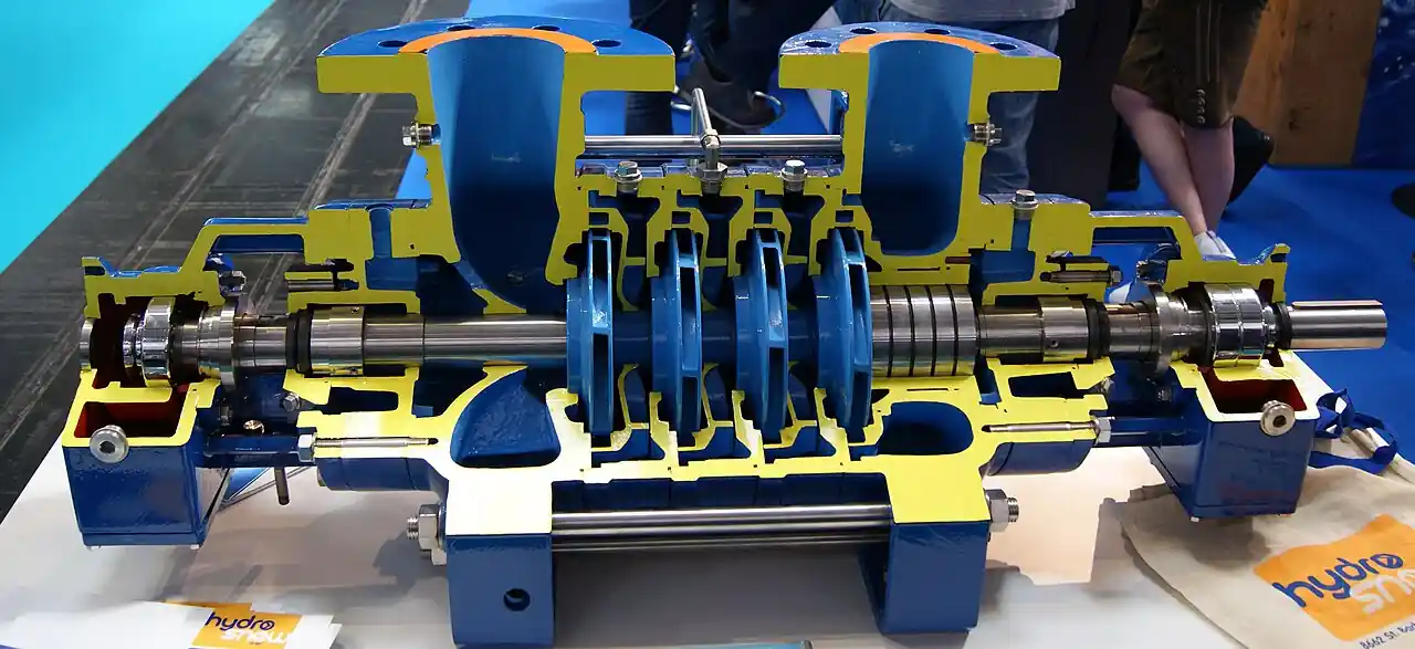
A boiler feed pump is a multistage centrifugal pump that lifts feedwater from a deaerator or feed tank to boiler pressure with enough margin to hold full firing rate flow against drum pressure, superheater pressure drop, feedwater control valve drop, and pipe losses combined. Impellers sit in series on one shaft, each stage adding a share of the total head, which is why the same product family spans package boiler rooms at 10 to 30 bar discharge and utility power plants at 200 bar and more, moving water at 105 to 180 deg C that sits within a few degrees of its saturation pressure. Plant documents shorten the name to BFP, and the terms boiler feedwater pump and feedwater pump all name the same machine. Shaft inputs run from under 10 kW on a small skid to more than 20 MW on a full scale utility barrel pump.
Procurement engineers meet these pumps in industrial steam plants, combined heat and power, biomass and waste to energy boilers, heat recovery steam generators behind gas turbines, and fossil utility units where two 50 percent pumps feed one boiler. The decision this page settles is narrow and practical: which API 610 body configuration the duty earns, how much NPSH margin the deaerator must actually deliver, which seal plan survives the feed temperature, and how minimum flow protection is wired into the station. The answer lands as an RFQ line set, configuration and stages and materials and seal plan and driver, and every chapter below feeds that line set so the pump is bought against measured duty rather than a catalog corner point.
This page treats the boiler feed pump as a purchasing object: how series staging reaches boiler pressure, what NPSH margin the deaerator geometry must deliver, which API 610 configuration each pressure and temperature band earns, how seal plans and minimum flow protection keep the machine alive, and how all of it combines into a defensible RFQ. It is written for engineers who issue purchase specifications, not for readers who want a brochure summary.
Chapter 1 / 06
What a Boiler Feed Pump Is and What Is Being Decided
The architecture is the product. A boiler feed pump stacks impellers in series: each stage takes discharge from the one before it, so heads add rather than blend, and the machine reaches hundreds of metres of head at modest impeller diameters. Head per stage runs 100 to 400 m in the practical family, stage counts run 3 to 12, and test efficiencies run 70 to 85 percent depending on specific speed and stage loading. That series architecture is what separates this machine from a single stage general service pump, and it is also what creates its three signature design burdens: axial thrust that must be balanced, suction pressure that must be guarded against flashing, and shaft power that must be shed at low flow. Every chapter of this page is one of those burdens made purchasable.
What is actually being decided in this purchase is a system match, not a flow and head lookup. The buyer commits to a body configuration, ring section or axially split or barrel casing; to a first stage arrangement that sets the NPSH requirement the deaerator must satisfy; to a seal plan with its cooling services; to materials matched to feedwater temperature and chemistry; and to minimum flow protection that decides whether the pump survives its worst operating hour. A boiler feed pump bought on rated flow and discharge pressure alone will fail either at commissioning, when the deaerator cannot hold the liquid level the NPSH calculation assumed, or in the first year, when sustained low load erodes the internals that the datasheet never mentioned.
The neighbor map is worth drawing early, with the full comparison reserved for chapter 5. The generic multistage pump page on this site covers the clean, cool water duty: booster sets, reverse osmosis feed, high pressure rinse. This page is the hot, deaerated, code adjacent branch of the same family. At the small end, a regenerative turbine pump or a compact ring section unit carries package boilers under about 20 bar. Where the water must not leak at all, a canned motor pump or a magnetic drive pump replaces the sealed machine in small and medium hot condensate duty. Where the requirement is high pressure at low flow, chemical injection and hydrotest duty, a plunger pump owns the ground. And the gear pump that appears beside every large BFP skid is there for lube oil forwarding, a different machine on a different datasheet, never a substitute for the feed duty itself.
Four standards organize the datasheet. API 610 (ISO 13709) is the centrifugal pump standard for petroleum, petrochemical, and natural gas industries, and power plants buy its configurations by type designation: OH2 overhung, BB1 axially split, BB2 radially split barrel, BB3 axially split multistage. API 682 (ISO 21049) governs the mechanical seal plans quoted in chapter 4. Hydraulic Institute test and application guidance fixes how NPSH margin is stated, and ISO 9906 or the HI test code backs the performance test the RFQ should demand. On the boiler side, ASME Boiler and Pressure Vessel Code rules apply to the pressure parts the pump feeds, not to the pump casing itself, but the feedwater chemistry the code culture enforces decides the pump materials. A datasheet that names none of these four is a price tag, not a specification.
The pump never works alone, and the RFQ should name its station. Suction comes from the deaerator through a short, straight line sized for 1 to 2 m/s with a temporary commissioning strainer. Discharge carries a check valve to stop reverse rotation and water hammer on trip, a minimum flow path back to the deaerator, and a feedwater regulating valve to the boiler. Monitoring is two instruments: a pressure transmitter on suction and another on discharge, with differential computed against the commissioning baseline. On the deaerator side, the pegging steam line and its drip leg drain through a steam trap, because a failed trap upsets deaerator heat balance and quietly moves the NPSHa the pump depends on. An RFQ that names the whole station buys a system that starts up the first time.
Chapter 2 / 06
How Series Staging Reaches Boiler Pressure
Walk the hydraulic path. Feedwater enters the first stage impeller eye at near saturation pressure, gains velocity and part of its pressure rise in the impeller, recovers more pressure in the diffuser or volute that surrounds it, and passes to the next stage inlet at the accumulated pressure of all stages before it. In words, total developed head equals roughly the sum of per stage heads minus interstage losses, and per stage head follows the impeller tip speed squared divided by gravity, which is why high head per stage is bought with speed as readily as with diameter. Utility barrel pumps run 4,000 to 7,000 rpm through gear increasers or two pole motors at 50 or 60 Hz for exactly this reason. The affinity laws govern the margins: flow scales with speed, head with speed squared, power with speed cubed, so a 10 percent speed reserve is a 21 percent head reserve and a 33 percent power question for the driver.
Axial thrust is the first structural consequence of staging. Every impeller face sees discharge pressure on its back and a lower pressure at its eye, so a 10 stage machine accumulates an axial force that no bearing absorbs alone. The standard answer is a balance drum at the discharge end: a rotating drum separated from the casing by a close running clearance, with discharge pressure on one face and a balance line returning its rear chamber to suction pressure on the other. The drum cancels most of the thrust, the balance line keeps its reference pressure honest, and a tilting pad thrust bearing carries the residual plus transient loads. This matters to a buyer because balance drum wear is a slow, measurable failure: as clearance opens, the drum leaks more, efficiency falls, and the residual thrust on the bearing climbs until the bearing temperature trend announces it. Chapter 6 turns that trend into a maintenance rule.
NPSH is the suction story, and on a boiler feed pump it is decided by the deaerator, not by the pump. Feedwater leaves the deaerator at its saturation temperature, 102 deg C at atmospheric pressure up to 180 deg C in pressurized deaerators, so the liquid carries zero margin between its pressure and its vapor pressure at the source. The entire NPSH available is the static height of the deaerator water line above the pump centerline, plus any pressurization, minus suction line losses. NPSH required is a pump property read from the maker curve, and the margin between the two is a purchase number: a widely used floor is the larger of 1.0 m and 10 percent above NPSHr at rated flow, with more margin held at runout and at the lowest deaerator level the control system permits. Where the geometry cannot deliver, the pump side answers with a low NPSH first stage: a double suction first stage impeller, or an inducer ahead of the eye, both of which cut NPSHr at the price of sensitivity to inlet flow distortion.
Temperature shapes the seal. Between 105 and 180 deg C, the seal chamber sits on water that will flash if depressurized, so the mechanical seal is never asked to run on raw process fluid alone. API 682 plans do the work: Plan 21 takes discharge fluid through an orifice and a cooler into the seal chamber; Plan 23 circulates chamber fluid through a cooler with a pumping ring and is the efficient standard for hot water; Plan 31 pulls a cyclone separated stream from discharge for services with solids; Plan 32 injects a clean external flush. On a boiler feed pump the historical trouble is Plan 21 orifices plugged with magnetite and coolers fouled by hard water, which is why chapter 6 makes the cooling water circuit a maintenance line item. The seal plan line on the RFQ is therefore not boilerplate; it is the difference between a seal that lasts years and one that carbonizes its faces in a season.
Low flow is the operating story. Below roughly 25 to 30 percent of best efficiency flow, the internal flow field in a multistage pump separates: radial loads on the shaft rise steeply, stage matching collapses, discharge temperature climbs as efficiency collapses, and the first stage can approach incipient cavitation even with healthy suction pressure. The protection is a minimum flow path: either an automatic recirculation valve that senses flow and opens a bypass internally, or an external loop in which a globe control valve modulates bypass back to the deaerator off a flow measurement, sometimes with a manual globe valve bypass around the automatic valve for startup and testing. Which arrangement to buy is a chapter 5 decision with a chapter 6 maintenance cost, but the physics is settled here: a multistage feed pump run against a closed or nearly closed discharge converts shaft power into heat and radial load, and it does so quickly.
Driver and speed close the loop. Small industrial units take two pole induction motors direct coupled at 2,900 or 3,500 rpm. Medium and large units add gear increasers to reach the tip speeds their stage counts need, and variable frequency drives have become standard where the boiler load swings: a VFD lets the pump ride its curve instead of forcing the feedwater control valve to burn 10 bar of permanent drop, and it soft starts a machine whose rotor mass is measured in tonnes. The RFQ should state the driver envelope honestly, including the low load hours the VFD will impose, because minimum continuous flow and minimum speed interact on the stability map the maker must confirm.
Chapter 3 / 06
Types, Construction, and Duty Boundaries
Four body architectures cover the market, and the pressure and temperature of the duty pick among them. Ring section (segmental) pumps clamp a stack of stage chambers between inlet and outlet casings with tie rods: compact, economical, and standard on package boilers and small industrial plants up to roughly 40 to 80 bar discharge and moderate temperature. Axially split casing pumps split the casing on the shaft centerline plane, so the top half lifts for internal inspection without breaking suction or discharge piping; API 610 type BB1 covers the two stage versions, BB3 the multistage versions, and the architecture carries medium pressure feedwater and circulating duty across process plants and power stations. Radially split barrel casing pumps, API 610 type BB2, sleeve a stack of stage chambers inside a forged barrel: the construction of record for utility boiler feed above roughly 120 bar, tolerant of thermal transients and daily cycling, and the architecture behind the Sulzer HPT and Flowserve WXB and CHTA families listed in the sources. At the small end, an API 610 OH2 overhung single stage or short multistage serves auxiliary boilers and low pressure feed transfer.
Vertical construction exists for tight rooms and poor suction geometry. A vertical turbine pump in a suction can drops the first stage below grade, adding metres of static submergence that the deaerator elevation cannot: shipboard feed sets and plant retrofits with no NPSH headroom use this arrangement, trading the horizontal split for a can, a thrust motor mount, and a different maintenance posture. The buyer comparing horizontal and vertical bids should compare them on NPSH margin achieved and annual inspection effort, because the hydraulic duty is identical and everything else is layout.
Materials follow temperature and chemistry. Casings run ASTM A216 WCB carbon steel for cooler industrial duties and shift to chrome steels, ASTM A217 WC6 and WC9 classes, as feed temperature and pressure rise toward utility conditions, with C12A appearing on high temperature cycling duty. Impellers and diffusers are CA6NM or 13 percent chromium class stainless, hard enough for the erosive magnetite transport that circulates in feedwater systems, with increased erosion allowances where the chemistry program is young. Shafts are 4140 class alloy or 17-4 PH stainless, stiff for their length because interstage deflection shows up first as wear ring contact and then as vibration. The feedwater chemistry itself, all volatile treatment or phosphate programs and its oxygen scavenger residuals, decides whether these defaults hold or the order needs a metallurgy note, and the RFQ should attach the water chemistry as a document rather than a sentence.
The duty boundaries are about temperature and flow, not just pressure. Feed temperature above about 140 deg C pushes the design toward barrel or axially split bodies with proper thermal management, because ring section tie rods distribute thermal stress poorly and leak across stage joints on cycling duty. Continuous operation below about 30 percent of best efficiency flow is outside the envelope of any of these machines without recirculation, as chapter 2 established. And water with suspended solids, mill scale from new pipe, or oil carryover from a troubled condensate system attacks exactly the close clearances that define the machine, which is why commissioning filters and oil monitoring are chapter 6 subjects. The architecture table below fixes the boundaries a specifier can quote.
Architecture
API 610 type
Typical envelope
Where it earns its cost
Ring section, tie rod
non-API or OH class
5 to 80 bar, 105 to 150 deg C, 5 to 200 m3/h
Package boilers, small industrial plants, skid duty
Axially split casing
BB1 two stage, BB3 multistage
40 to 180 bar, to about 180 deg C
Medium plants, CHP, inspection without pipe breaks
Barrel casing
BB2 radially split
120 to 350 bar, 140 to 180 deg C, to 1,500 m3/h class
Utility boilers, HRSGs, cycling and high head duty
Overhung single stage
OH2
under about 20 bar, auxiliary duty
Auxiliary boilers, low pressure feed transfer
Vertical can type
VS1 or VS3 class vertical turbine pump
medium pressure, NPSH constrained rooms
Shipboard and retrofit feed stations needing submergence
Chapter 4 / 06
Key Specification Parameters
The table below decodes the datasheet lines that decide whether a quoted boiler feed pump matches the station. Each row is purchase defining; the paragraphs after it explain what to demand and what a weak answer looks like.
Parameter
Typical range or options
What it decides
Rated flow and discharge pressure
5 to 1,500 m3/h; 10 to 350 bar
Machine size class, stage count, and driver power
Differential head and stages
100 to 400 m per stage, 3 to 12 stages
Speed requirement, rotor length, and thrust management
Feed temperature
105 to 180 deg C from deaerator
Body architecture, material class, and seal plan
NPSHr at rated and runout
2 to 15 m curve; first stage options below 2 m
Whether the deaerator elevation is adequate at all
API 610 configuration
OH2, BB1, BB3, BB2, VS class vertical
Test, material, and QA regime applied to the order
Seal plan per API 682
Plan 21, 23, 31, 32, arrangements 2 or 3
Seal life, cooling services, and flush cleanliness
Minimum continuous flow
typically 25 to 30 percent of BEP flow
Recirculation hardware and low load operating limits
Efficiency at rated point
70 to 85 percent by size and speed
Lifetime energy cost, the largest line in the ownership sum
Driver
2 pole motor, gear increaser, VFD package
Speed envelope, start behavior, and control range
Materials
WCB to WC6 and WC9 casings; CA6NM impellers
Corrosion and erosion margin against feed chemistry
The NPSH row deserves its own paragraph because it is where quotations go quiet. Demand the NPSHr curve from rated flow through runout, not a single point, and demand the first stage arrangement named: standard eye, double suction, or inducer. Then do the station arithmetic in the open: deaerator operating pressure plus liquid level above pump centerline, minus vapor pressure at that temperature, minus suction line losses at runout, and compare against NPSHr with the margin floor from chapter 2. A supplier who will not publish NPSHr at runout is hiding the point where the pump cavitates on a load swing, and that point always arrives during the first summer load peak.
The seal plan row is the second quiet one. The mechanical seal quotation should name the API 682 plan, the seal chamber pressure and temperature it assumes, the cooler duty in kW, and the cooling water flow and quality it needs. Plan 23 is the default for hot feedwater because it circulates a small cooled loop instead of cooling the whole flush stream; Plan 32 makes sense when the plant can supply clean condensate at pressure, in which case the RFQ must add a Y strainer and isolating valve pair on that supply so the seal never sees strainer bypass debris. Plan 21 works when the water is clean and the cooler is maintained; its orifice belongs on the spares list from day one. Whichever plan is chosen, the seal support hardware is a pressure part of the station and belongs on the same datasheet, with the same seriousness as the pump flanges.
Instrumentation rows close the specification. A pressure transmitter at suction and another at discharge, feeding the historian, give the differential trend that catches wear ring and balance drum wear years early. A temperature transmitter on each bearing housing and one on the seal pot or cooler outlet catches the two failures that announce themselves as heat: thrust bearing overload and seal cooling loss. Both transmitter types are cheap at order time and expensive to retrofit on a hot machine. Where the discharge block valve can isolate a running pump against its minimum flow path, a small safety relief valve or thermal relief on the discharge piping protects the trapped volume, and its set pressure belongs in the piping spec next to the pump datasheet rather than in a separate argument at startup.
The configuration table below compresses the API 610 decision into the form a specification meeting can argue from; the selection chapter then applies it to real duties.
Configuration
Buy it when
Verify before order
OH2 overhung, short multistage
Auxiliary and package boilers under about 20 bar
NPSHr against feed tank level; seal plan at temperature
Ring section industrial
10 to 80 bar process and CHP plants, steady load
Tie rod joint behavior on thermal cycling; stage gasket spares
BB1 or BB3 axially split
40 to 180 bar, inspection access valued, water hammer exposure
Split joint gasket design; rotor stiffness at runout
BB2 barrel casing
Utility and HRSG duty above about 120 bar, cycling plants
Barrel material and test certificates; balance line routing
Vertical can, vertical turbine pump based
NPSH starved rooms, shipboard, retrofit basements
Can depth versus NPSHa; thrust bearing and motor support
Chapter 5 / 06
Selection Decision Factors and RFQ Language
The decision sequence below runs as a checklist in a specification meeting, and each step eliminates a class of quotations before any price comparison starts.
Fix the duty point in numbers: rated flow, maximum flow with margin, boiler drum pressure, feed line and heater losses, and control valve drop, then read total differential head from them, not from the boiler nameplate alone.
Compute NPSHa honestly at the worst credible combination of low deaerator level and hot start, then hold the margin floor from chapter 2 and buy a low NPSH first stage only if the geometry still fails.
Pick the API 610 configuration against pressure, temperature, and cycling severity using the chapter 4 table, and write the type designation into the RFQ by name.
Set the seal plan with its cooling services, flush source, and strainer hardware, and state feedwater chemistry as an attached document.
Fix minimum flow protection: automatic recirculation valve or globe control valve loop, its setpoint, its destination, and the manual startup bypass around it.
Size the driver for runout power plus margin, decide VFD against the load profile, and state the low load hours the pump will actually see.
Name the station: discharge check valve, warming and recirculation lines, suction and discharge pressure transmitter, bearing temperature transmitter points, and relief hardware.
Fix the evidence: performance test to ISO 9906 or HI with NPSHr demonstrated, API 682 seal qualification, material certificates, and the vibration acceptance limits applied at test.
Against the neighboring machines, the comparison a specifier actually needs runs as follows, and it belongs here in the selection chapter rather than in the page title. The generic multistage pump of the water supply world handles cool clean water and shares the series staging but none of the thermal and code burdens. The regenerative turbine pump carries small package boilers to about 20 bar with a compact close coupled machine that tolerates entrained vapor, at the price of modest efficiency and tight wear clearances. A canned motor pump or a magnetic drive pump removes the mechanical seal entirely for hot condensate and zero leak duty, and is the honest choice where a leak is unacceptable and the pressure is moderate; both lose efficiency and add motor cooling complexity as size grows. A plunger pump reaches pressures no centrifugal machine matches, but only at tens of litres per minute, which suits chemical injection and hydrotest work and never drum boiler feed volume. The gear pump on the skid is lube oil service, full stop. Within the centrifugal family itself, a vertical turbine pump in a can trades horizontal accessibility for suction submergence. The boiler feed pump earns its purchase when the duty is high head, hot, deaerated water at flows from a few tens of cubic metres per hour upward, and that is the whole of it.
The application map below turns that comparison into a table the project file can carry.
Application
Construction to specify
Check before order
Package boiler, 10 to 20 bar
Ring section or OH class multistage, Plan 23 seal
Feed tank level versus NPSHr; VFD against load swings
Test witness points; balance line and thrust monitoring
Shipboard or basement feed station
Vertical turbine pump in suction can
Can depth versus NPSHa; removal clearance above
Zero leak hot condensate transfer
Canned motor pump or magnetic drive pump
Pressure and temperature envelope; cooling circuit duty
The RFQ block should be written once and reused. A complete block reads: quantity and standby philosophy; rated, normal, and maximum flow with boiler pressure at each; feedwater temperature and chemistry report attached; deaerator pressure, minimum operating level, and suction line layout, so NPSHa is computable by both parties; total differential head and the duty split behind it; API 610 type designation; stage count and head per stage; NPSHr curve through runout and first stage arrangement; materials by ASTM designation for casing, impellers, shaft, and wear parts with erosion allowance; API 682 seal plan with cooler duty and flush source including its Y strainer; minimum continuous flow and the recirculation arrangement, automatic valve or globe control valve loop with startup bypass and a manual globe valve; driver rating, speed or VFD envelope, and low load hours; station hardware, discharge check valve class, pressure transmitter points, temperature transmitter points, and a safety relief valve or thermal relief on any isolatable discharge section; test requirements, performance and NPSH to ISO 9906 or HI, witness level, and acceptance limits; and the spares priced with the machine, wear rings, balance drum, seal cartridge, and first fill of gaskets. A quotation returned without the NPSHr curve or the seal cooler duty is incomplete at any price.
Chapter 6 / 06
Installation, Standards, Failure Modes, and Maintenance
Installation quality decides whether the rotor reaches its design life. Alignment is the first discipline: driver to gearbox to pump, hot alignment checked at feed temperature, because a machine whose casing grows 0.3 mm off its cold line destroys its coupling and thrust bearing in a season of starts. Suction piping is short, straight, and free of air pockets, with the temporary commissioning strainer removed after flush, and the discharge check valve mounted where its slam on a trip cannot water hammer the pump casing. Warming arrangements keep the standby pump tracked to the running unit: a warmup orifice line from discharge to the standby suction side, and on the deaerator the pegging steam drip leg with its steam trap maintained, since a failed trap there quietly changes deaerator pressure and the NPSH the standby pump assumes. Grout, anchor bolts, and pipe loads belong on the installation record; most chronic vibration complaints trace to a pipe load applied to a nozzle years after commissioning.
Commissioning writes the baseline the machine is judged against for its life. Flush the suction path before first start, run the pump on its minimum flow path at first, and record the suction and discharge pressure transmitter pair, seal plan temperatures, and vibration signature at three flows: minimum, normal, and full load. File the NPSH demonstrated at test beside the NPSHa computed at commissioning, and keep both. Verify the minimum flow hardware by forcing it, not by hoping: the automatic recirculation valve or the globe control valve loop must be seen to open, and the manual globe valve bypass left closed and tagged. On VFD packages, capture the vibration signature across the speed range, because a resonance that hides at rated speed often lives at 60 percent of it.
The standards frame is explicit on this machine, which is a change from much of the encyclopedia. API 610 fixes the mechanical design, test, and QA regime by type designation. API 682 fixes the seal and its plans. Hydraulic Institute application guidance and the ISO 9906 test code fix how performance and NPSH are measured and stated. On the boiler side the ASME code governs the pressure parts the pump feeds and the chemistry culture that protects them, and a feedwater pump order should carry the chemistry document as surely as it carries the flange standard. Where the plant audits machinery, API 670 style vibration and temperature monitoring belongs on the bearings from day one rather than as a post incident upgrade.
Failure modes in service follow a short and predictable list. Cavitation from deaerator level loss leads it: a falling suction pressure transmitter trend, rising noise, and impeller eye erosion that a margin calculation would have prevented. Low flow erosion follows, glassy striations on impeller vane outlets and diffuser throats from recirculation inside the stages, traceable to a minimum flow scheme that was bypassed or mis set. Balance drum wear shows as slowly falling efficiency and rising thrust bearing temperature, visible months ahead in the differential pressure trend. Seal distress shows at the temperature transmitter on the cooler or seal pot: a climbing Plan 23 outlet temperature means fouled cooler or plugged orifice, and faces that run hot on flashing water carbonize and fail within weeks. Check valve slam on trips hammers the discharge path, and repeated events crack piping and loosen foundation bolts; the fix is a damped or spring assisted valve chosen at order time. Finally, water chemistry excursions, oxygen or pH upsets, attack the same close clearances from the corrosion side, which is why the chemistry report belongs inside the pump file and not only in the water treatment log.
Maintenance intervals scale with duty severity and cycling. Monthly: seal plan temperatures, bearing temperatures, and the suction and discharge differential against baseline, a five minute trend review that catches every failure mode above in its infancy. Quarterly: vibration readings at fixed speeds, cooling water strainer service, and function testing of the minimum flow path, including the Y strainer on any Plan 32 flush supply. Annually: coupling and alignment check on a hot shutdown, seal inspection at the first scheduled opening, and steam trap surveys on the deaerator steam services. At the first major internal inspection, typically three to five years by cycling severity, measure wear ring and balance drum clearances against the maker limits and buy the next rotor against measured wear, not against calendar habit. None of these checks costs a tenth of one unplanned boiler trip, and every one of them writes a number the next RFQ can use, which is how a purchasing file gets smarter instead of just older.
FAQ
What makes a boiler feed pump different from a general purpose multistage pump?
A general multistage pump moves cool, clean water with generous pressure margin over vapor pressure. A boiler feed pump moves deaerated water at 105 to 180 deg C, within a few degrees of saturation, against drum pressure plus line and control valve losses. That duty forces low NPSH first stages, hot service mechanical seal plans, chrome steel materials, balance drum thrust management, and minimum flow protection, none of which the clean water machine carries. The series staging architecture is shared; the thermal and suction engineering is the difference.
How much NPSH margin does a boiler feed pump need?
Work from the deaerator: NPSHa equals deaerator pressure plus liquid level above the pump centerline, minus vapor pressure at feed temperature, minus suction line losses at the flow in question. A widely used floor is the larger of 1.0 m and 10 percent above NPSHr at rated flow, with additional margin held at runout and at the lowest operating level. Because the source liquid sits at saturation, the level term does nearly all the work, and deaerator elevation is effectively a purchased NPSH decision made at plant layout time.
Which API 610 configuration should the RFQ name?
Name it by pressure, temperature, and cycling severity. OH2 covers auxiliary and package boilers under about 20 bar. Ring section industrial pumps carry 10 to 80 bar steady duty. BB1 and BB3 axially split bodies serve roughly 40 to 180 bar where internal inspection without breaking piping is valued. BB2 barrel casing pumps are the utility standard above about 120 bar and on cycling HRSG duty. Writing the type designation into the RFQ fixes the design, test, and QA regime the supplier must meet.
Why do mechanical seals on feed pumps fail early?
Almost always heat. Feedwater near saturation flashes across seal faces when chamber conditions drift, and faces running hot on flashing water carbonize within weeks. The usual root causes are a fouled Plan 23 cooler, a plugged Plan 21 orifice, lost cooling water flow, or a flush supply strainer that was bypassed. The fixes are purchased, not heroic: size the cooler for the real temperature, put the orifice and strainer on the spares list, instrument the seal outlet with a temperature transmitter, and trend it.
What minimum flow protection does a boiler feed pump need?
Below roughly 25 to 30 percent of best efficiency flow, stage flow separates, radial loads rise, and discharge temperature climbs, so the protection is a permanent bypass path. An automatic recirculation valve senses flow and opens internally with no external actuation. An external loop uses a globe control valve modulating off a flow measurement back to the deaerator, usually with a manual globe valve bypass for startup and testing. Either works; the failure is specifying neither and running the pump against a nearly closed feed valve.
What does the balance drum do?
Series impellers accumulate a large axial force toward suction. A balance drum at the discharge end, with a balance line returning its rear chamber to suction, cancels most of that force hydraulically, leaving a tilting pad thrust bearing to carry the residual and transient load. As the drum clearance wears open, leakage grows, efficiency falls, and residual thrust on the bearing rises. The signature is a slow differential pressure decline with a slow bearing temperature rise, which the suction to discharge pressure transmitter pair catches years early.
What materials suit feedwater service?
Follow temperature and chemistry. Casings run ASTM A216 WCB for cooler duty and WC6 or WC9 chrome steels as temperature and pressure rise, with C12A on high temperature cycling service. Impellers and diffusers are CA6NM or 13 percent chromium class stainless for erosion margin against magnetite transport. Shafts are 4140 class alloy or 17-4 PH. Attach the feedwater chemistry report to the RFQ, because oxygen and pH excursions attack the same clearances that define pump health, and material upgrades cannot compensate for a chemistry program that is not run.