5G industrial modules are purpose-built radio units that package a 5G modem, baseband, RF front-end, and industrial-grade I/O into a single embeddable device, designed to slot into PLCs, AGVs, machine vision cameras, and edge gateways inside factories [S1]. The Manufacturing Institute study reports 91% of manufacturers view 5G as important to their future, 56% planned to test or use 5G in their facilities by end-2021, and 88% expect 5G to allow engineers to troubleshoot remotely [S2].
Unlike consumer 5G modules, industrial modules must survive -40 °C to +85 °C operating ranges, withstand 5 g RMS vibration, and pass IEC 60079-classified hazardous-area certifications where Zone 2/Class I Div 2 applies [S1]. The Manufacturing Institute quantifies the upside: average equipment productivity gains of ~42% and worker productivity gains of ~41% are anticipated as 5G-enabled applications scale [S2].
Module Form Factors and the Equipment That Builds Them
Industrial 5G modules ship in three dominant form factors, each driving a different set of surface-mount and test requirements on the production line: M.2 (30×42 mm or 30×52 mm) for edge gateways and IPCs, Mini PCIe (51×30 mm) for legacy industrial PCs, and LGA solder-down modules (typically 32×40 mm) for AGVs, robots, and OEM embedded designs [S1]. Surface-mount assembly uses pick-and-place machines with ±25 µm placement accuracy, nitrogen-purged reflow ovens profiled to a peak of 245-250 °C for SAC305 lead-free solder, and 3D solder paste inspection (SPI) ahead of placement to keep tombstoning below 50 ppm on QFN baseband packages [S3].
Test cells for 5G module production stack in this sequence: ICT (in-circuit test), boundary-scan JTAG, RF calibration over a conducted non-signaling (CNES) chamber, then over-the-air (OTA) anechoic chamber verification against 3GPP TS 38.101-1 radiated power and EVM limits [S3]. Throughput typically maxes out at 9.6 Gbps for Wi-Fi 6, 1 Gbps for 4G LTE, and 10 Gbps for 5G under the PwC comparison table; 5G latency drops to 1-10 ms versus 20 ms for Wi-Fi 6 and 30-50 ms for 4G [S3].
RF, Antenna, and Over-the-Aire Validation Equipment
Industrial 5G modules integrate multi-band RF chains covering sub-6 GHz FR1 (n1, n3, n5, n7, n8, n20, n28, n38, n40, n41, n77, n78, n79) and optionally mmWave FR2 (n257, n258, n260, n261), which means RF calibration must sweep dozens of bands at temperatures from -40 °C to +85 °C in a thermal-shock chamber [S1]. A typical production anechoic chamber uses a dual-polarised probe at 1-2 m distance, a vector signal analyzer, and a 3GPP-conformance test set; radiated spurious emission limits follow 3GPP TS 38.101-1, and EVM targets sit at 4% for QPSK and 3.5% for 64-QAM on FR1 [S3].
Manufacturers pairing 5G modules with linear guide driven gantries for AGV test fixtures should size the chamber door and rail travel to clear the largest UUT; a 4 m × 4 m chamber with a 3-axis positioner covers most module-level OTA work without retrofit. Connection density is the headline spec buyers should track: 5G supports 100 connected devices per cell area versus 8 for Wi-Fi 6 and 12 for 4G, so factory-floor slice planning depends on per-area device count, not just throughput [S3].
Comparison: M.2 vs Mini PCIe vs LGA Modules for Production
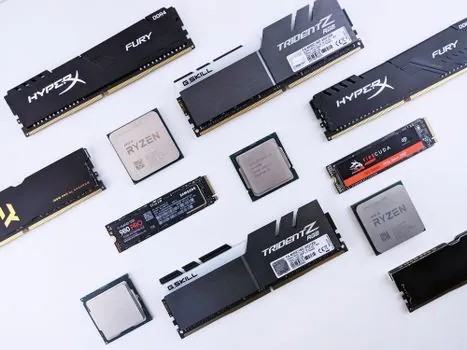
Decision-makers should weight four criteria when picking the module format for a given industrial design: integration density, host-side ruggedness, rework cost, and total BOM. M.2 modules win on host flexibility (standard M.2 B-key or M.2 B+M key sockets on most industrial motherboards) but add a mated connector rated for only 30-60 mating cycles, which limits field serviceability. Mini PCIe remains popular in legacy IPCs but is being phased out of new designs.
For plants deploying 5G AGVs, cross-roller guided stages are common in the crossed roller guide test rigs that simulate 50,000 hours of vehicle duty; if your UUT is a solder-down module, plan X-ray and rework tooling rather than swap-out M.2 spares. Throughput per module type is identical (the modem is the same), so the choice is mechanical, host-architecture, and total-cost driven [S3].
Network Integration: Slicing, URLLC, and Edge Compute
URLLC (Ultra-Reliable Low-Latency Communication) is the 5G feature that closes the loop on industrial control: 1 ms user-plane latency at 99.999% reliability for a single packet within a 1 ms window is the design target, and Multi-access Edge Computing (MEC) places the application server inside the factory 5G core so the round-trip stays under 5 ms [S1]. Network slicing lets a single physical 5G RAN carry eMBB (cameras, AR maintenance), URLLC (motion control, safety), and mMTC (thousands of low-rate sensors) on isolated virtual pipes, with the mMTC slice supporting up to 1 million devices per square kilometre versus 4G's ~60,000 cap [S3].
For inspection stations running non-destructive testing equipment on welds and casting surfaces, the URLLC slice plus an on-prem MEC node is the practical pattern: the camera streams 4K/60 frames over 5G, the inference engine runs within 5 m of the cell site, and the reject signal returns to the line in under 10 ms. Plants should also plan anti-static equipment at every 5G module handling station; sub-100 V tribo-charging on a solder-down LGA module is enough to pop an ESD diode and kill RF calibration before final test.
Manufacturing Equipment Line Layout and Yield Targets

A typical 5G industrial module line runs SMT placement, AOI, X-ray, depanel, ICT, firmware flash via JTAG/SWD, RF calibration, OTA chamber, burn-in (-40 °C to +85 °C, 48-96 h), and final pack-out, with target first-pass yields of 98-99% on placement, 95-97% on RF calibration, and 99.5%+ on OTA [S1]. Reflow ovens are profiled to a 245-250 °C peak with 60-90 s above liquidus, ramp rates held under 2 °C/s to protect QFN thermal pads, and nitrogen atmosphere with O2 below 1,000 ppm to suppress voiding under BGA ground pads [S3].
For the additive manufacturing material side, factory tool builders increasingly 3D-print jigs and antenna test fixtures in PA-CF or PEKK; the printed fixtures cut lead time from 4-6 weeks to 2-3 days and survive 10,000+ OTA cycles. Burn-in burn-in rates of 0.3-0.5% are typical for industrial-grade parts versus 1-2% for commercial-grade; plant audits should request the burn-in failure Pareto, not just the headline AQL [S1].
Buyer Checklist and Trackable Signals
Spec-first buyers should demand four documents before signing a PO: the 3GPP TS 38.101-1 conformance report (FR1 bands covered, EVM plots), the IEC 60068-2 shock/vibration profile the module is qualified to, an MTBF figure (industrial-grade modules typically exceed 500,000 hours at +25 °C), and a confirmed 10-year component-lifecycle commitment from the modem vendor [S1][S3]. On the manufacturing equipment side, ask for SPI/AOI placement accuracy certificates (≤25 µm @ 3σ), RF chamber path-loss calibration within ±0.5 dB traceable to NIST, and an X-ray voiding report with acceptance limits under 25% pad void area on BGA ground pads [S3].
Trackable signals for the next 12-18 months: 3GPP Release 18 (5G-Advanced) feature freeze milestones, which govern the next generation of industrial modules with native AI/ML at the air interface, and the rollout of 5G-ACIA (5G Alliance for Connected Industries and Automation) testbeds that publish reference line layouts for vendors [S1]. Plants evaluating a new 5G module line should also benchmark against the deburring machine working principle options for connector housings and against construction machinery and equipment guides for the facility-side rigging, since module fabs often share shop-floor culture with heavy-equipment plants. The 2021 Manufacturing Institute baseline (91% / 56% / 88% / 91%) remains the cleanest public dataset for sizing the addressable 5G-manufacturing market [S2].