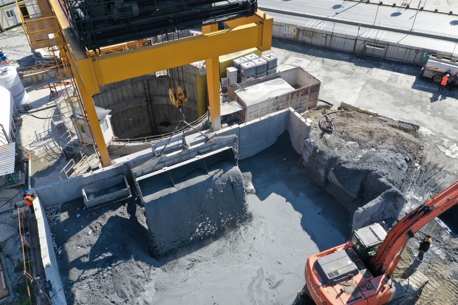
On-site installation of an aluminium-foundry degassing and refining unit follows a fixed mechanical-then-process sequence: foundation and skid levelling, launder tie-in, rotary degasser body set, gas-supply skid, dosing/flux feeder, filtration or baghouse tie-in, refractory cure, argon-line leak test, then hot commissioning with metal [S2].
Hydraulic-power skids, cross-roller-mounted rotor head carriages, and the gas-regulation module are the three sub-assemblies that arrive loose and are field-aligned; a linear guide on the rotor head carriage is the most common wear point after 12 months of service.
Installation Scope and Boundary Definition
The "degassing & refining unit" is the boundary between furnace-tap and casting; it includes rotary degasser + treatment box, gas-supply skid, flux/tablet feeder, melt filtration, and a hydraulic power unit for head tilt and rotor drive [S2].
A typical 30-50 t/h line ships as 4-6 skids plus an electrical control cabinet; total installed mass is 8-18 t depending on treatment-box volume (1.0-3.0 m³), and footprint is roughly 6 m × 3 m plus a 2 m operator aisle.
Out of scope: furnace, holding vessel, launder refractory upstream, and the downstream casting pit; the boundary tie-in flanges on the launder and the spout are the spec-driven interface.
Pre-Install Acceptance Criteria for the Equipment Itself
Before crane pick, the rotary degasser body must be checked for rotor-shaft run-out under 0.20 mm at the impeller seat and refractory thickness 150-200 mm at the sidewall per OEM drawing [S2].
The graphite rotor (typical OD 180-250 mm, length 600-900 mm) is the consumable that sets the next service interval; spares ratio is 1:6 (one spare per six installed) for continuous casting plants.
Foundation, Levelling, and Skid-to-Skid Alignment
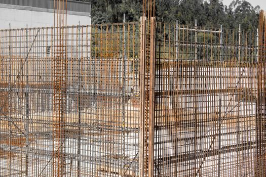
Foundation bolts are M24 grade 8.8 on a 600 mm × 600 mm × 400 mm pad; skid-to-skid elevation tolerance is ±2 mm across the full 6 m length, and launder flange faces must be parallel within 0.5 mm/m to avoid molten-metal leakage.
Rotary degasser body sits on a crossed roller guide tilt carriage so the operator can swing the head out for rotor change without a crane; the carriage rails must be shimmed to 0.05 mm/m flatness over the full travel.
Skid-to-skid process piping (argon, nitrogen, hydraulic return) is stainless 304L Sch 40 for gas, and seamless 16 Mo3 for the hydraulic supply above 100 °C service; both are pre-flushed and capped at the factory.
Refractory, Pre-Heat, and First-Melt Sequence
Refractory in the treatment box is a 70% Al₂O₃ low-cement castable, cured 24 h ambient + 24 h at 110 °C + 8 h ramp to 700 °C, before the first metal is admitted; cold-start pouring onto uncured refractory cracks the box within 5-10 heats.
Pre-heat gas flow is nitrogen at 5-8 Nm³/h, with the lance out of the bath, until the box wall reads 600-700 °C on the Type-K thermocouple; only then is the rotor lowered and argon turned on at 15-25 l/min for the first 10 min of bath purge.
Commissioning Tests and Acceptance Thresholds

PLC/HMI point-to-point check covers: rotor speed, argon flow per port, bath temperature, box pressure (-50 to +50 Pa under hood), and the interlock that drops argon if the rotor current spikes above the OEM set point (typical 25-35 A on a 30 kW drive).
Common Failure Modes and What Triggers Repair vs Replacement
Rotor-shaft run-out above 0.5 mm, or visible cracks in the graphite after 150-200 h, means rotor replacement; a worn linear guide on the tilt carriage shows as 1-2 mm of head-side play and is repaired by re-shimming the rail (replace if the raceway shows brinelling deeper than 0.05 mm).
Hydrogen above 0.15 ml/100 g after a full 20-min treatment points to either argon starvation, a porous graphite rotor, or a bath temperature below 715 °C — repair the seal first, then replace rotor, then check the hydraulic power unit for head-lift pressure (target 140-160 bar, drop below 120 bar triggers pump service).
Treatment-box refractory spalling above 5% of the hot face is a box-reline trigger, not a patch; reline interval on a continuous 30 t/h line is 9-14 months depending on melt temperature overshoots.
Standards, Documentation, and What "Done" Looks Like
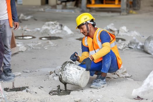
Hand-over pack: as-built GA drawing, refractory cure log, argon leak-test certificate, RPT density-index report, motor and drive data sheets, and the OEM commissioning checklist signed on all three test items.
Safety boundaries the installer must respect: argon line purges with 3× line volume of N₂ before oxygen service, and the hood vent ties to a baghouse sized for 4,000-6,000 Nm³/h at -100 Pa; chlorine-bearing fluxes require a packed-tower scrubber, not a dry baghouse.
For a related process reference on bearing handling during the rotor-head install, see the bearing fit and lubrication field guide; refractory density choice tracks Rock Wool density and form logic for the outer shell. Verify the degassing unit rotor current stays under the OEM trip curve for the first 50 heats before closing the punch list.